Advertisement
Quick Links
Instruction Leafl et IL032043EN
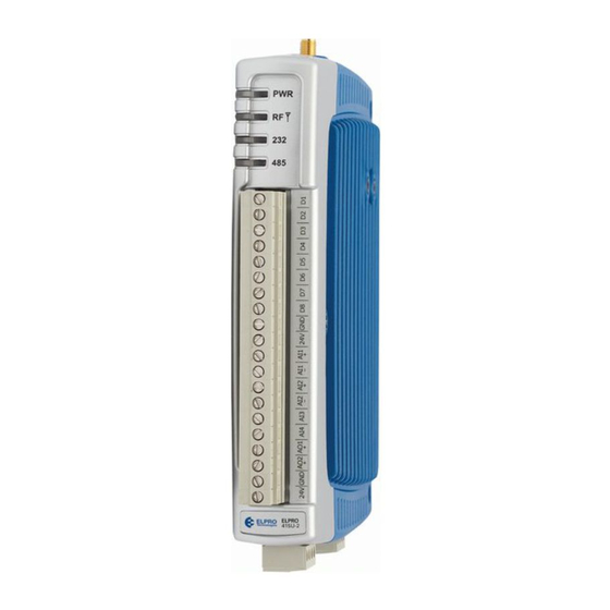
415U-2 wireless mesh networking I/O and gateway
installation guide
Statutory requirements
FCC: This device complies with
Part 15.247 of the FCC Rules.
Operation is subject to the
following two conditions:
This device may not cause
•
harmful interference.
This device must accept any
•
interference received, including
interference that may cause
undesired operation.
FCC: Unlicensed operation limits
the radio power. High gain aerials
may only be used to compensate
for cable losses.
WARNING - EXPLOSION
Do not disconnect the device while the
circuit is live unless the area is known
to be non-hazardous.
The 415U-2 module ships from
the factory in configuration mode.
The radio locale, frequency, and RF
power need to be configured using
the embedded web pages before
use.
Effective April 2015
Antenna installation
Use Figure 1 as a guide for installing an antenna and attaching it
to the module.
Figure 1. Antenna installation
Surge Arrestor
(recommended)
HAZARD
NOTE
Connecting to the module for confi guration
The default settings for the 415U-2 are as follows:
•
•
•
•
•
1. Connect a straight-through Ethernet cable between the
2. Open Internet Explorer on the PC.
3. Type "http://" followed by the IP address of the module and
Wavelength:
Antenna
360MHz = 32.7" (83cm)
512MHz = 22.8" (58cm)
Stress
Relief
Loop
Coaxial Cable
GND
415U-2
GND
at least 11 AWG (4 mm 2 )
Earth Stake
Provide good ground
connection to mast,
module, and surge
arrestor.
If ground conditions
are poor, use more
than one stake.
IP Address: 192.168.0.1XX, where "XX" is the last two digits
of the serial number shown on the printed label on the side of
the module
Subnet Mask: 255.255.255.0
Default Gateway: 192.168.0.1
Username: user
Password: user
module's Ethernet port and a PC.
press Enter.
1 Wavelength
*
(minimum)
Weatherproof
Connections
(recommended:
3M ™ 23 self-
bonding tape)
Mast
Earth Conductor
at least 5 AWG
(16 mm 2 )
For maximum
*
range, install
above local
obstructions.
Advertisement

Subscribe to Our Youtube Channel
Summary of Contents for Eaton 415U-2
-
Page 1: Installation Guide
NOTE Connecting to the module for confi guration The 415U-2 module ships from The default settings for the 415U-2 are as follows: the factory in configuration mode. IP Address: 192.168.0.1XX, where “XX” is the last two digits •... - Page 2 Instruction Leafl et IL032043EN 415U-2 wireless mesh networking I/O and gateway installation guide Effective July 2015 NOTE Confi guration switches Use the DIP switches in the All connections must be SELV <50 Vac and <120 Vdc. side access panel to select The following illustrations show the ports on the 415U 2.


Need help?
Do you have a question about the 415U-2 and is the answer not in the manual?
Questions and answers