
Related Manuals for HTP MICROCUT 600


Summary of Contents for HTP MICROCUT 600
- Page 1 MICROCUT 600 Owner’s Manual HTP America, Inc • 180 Joey Drive • Elk Grove Village, IL 60007 TEL: 847-357-0700 • FAX: 847-357-0744...
-
Page 2: Manufacturer's Warranty
This warranty shall not apply to any cutting machine which has been repaired or altered by unau- thorized service departments in any way so as in the judgment of HTP America, Inc. to aff ect its stability and reliability, nor which has been subjected to misuse, negligence or accident. -
Page 3: Safety Summary
injury and carefully read the message that SAFETY SUMMARY follows. Every worker respects the tools with which This symbol indicates that the they work. They know that the tools represent possibility of electric shock hazard years of constantly improved designs and exists during the operation of the developments. -
Page 4: Shock Hazard
SHOCK HAZARD the unit, cables, work area, or power cord are exposed to any form of atmospheric precipitation, or salt water spray. • Do not carry coiled cables around shoulders, WARNING or any other part of the body, when they are plugged into the unit. -
Page 5: Fire Hazards
• Provide bystanders with shields or helmets fl y 35 feet and can pass through small cracks fi tted with a #10 shade fi lter lens. and openings. If work and combustibles • Wear protective clothing. The intense light cannot be separated by a minimum of 35 of the cutting arc can burn the skin in much feet, protect against ignition with suitable, the same way as the sun, even through... -
Page 6: Plasma Arc Hazards
PLASMA ARC HAZARDS the coating is removed. Make certain the area is well ventilated, and the operator and all bystanders are wearing air-supplied respirators. WARNING • Do not weld, cut, or heat lead, zinc, cadmium, mercury, beryllium, or similar metals without seeking professional advice and inspection THE HEAT FROM THE PLASMA ARC CAN of the ventilation of the working area. -
Page 7: Additional Safety Information
ADDITIONAL SAFETY INFORMATION For additional information concerning welding and cutting safety, refer to the following standards and comply with them as applicable. • ANSI Standard Z49.1 – SAFETY IN WELDING AND CUTTING – obtainable from the American Welding Society, 550 NW Le Jeune Road, Miami, FL 33126 Telephone (800) 443-9353, Fax (305) 443- 7559 –... -
Page 8: Plasma Cutter Specifications
PLASMA CUTTER SPECIFICATIONS DESCRIPTION normally again. However you should wait at least ten minutes after the thermal protector Your new Plasma Cutter is designed as a clean, opens before resuming work. You must do this distortion free means of cutting through metal, even if the thermal protector resets itself before up to 1/2”... -
Page 9: Know Your Plasma Cutter
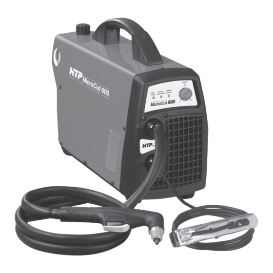
KNOW YOUR PLASMA CUTTER Figure 1 MICROCUT 600 1.ON/OFF SWITCH 6. AIR REGULATOR In the ON position the machine is ready for Adjusts the input air pressure - pull upward normal operation. All system control circuits to unlock - nominal air pressure setting is 65 are activated. -
Page 10: Plasma Cutter Installation
PLASMA CUTTER INSTALLATION POWER SUPPLY CONNECTION TORCH CONNECTION This plasma cutter is designed to operate on a properly grounded 230 WARNING!: BEFORE STARTING THE volt, 60Hz, single-phase alternating CUTTING OPERATIONS VERIFY THAT THE current (ac) power source fused with PARTS ARE PROPERLY ASSEMBLED BY a 30 amp time delayed fuse or circuit INSPECTING THE HEAD OF THE TORCH breaker. -
Page 11: Cutting Operation
MANUAL PURGE CUTTING OPERATION Oil in the air is a severe problem and must be avoided. PRELIMINARIES The unit is also equipped with an air fi lter which captures water and oil vapor. WARNING: The vapor collected can be drained out turning unplug the unit from the power supply before the drain knob located on the air fi lter. -
Page 12: Cutting With A Hand Torch
CUTTING • If the cutting arc is interrupted, and the torch trigger is still pressed, the pilot arc comes A. CUTTING WITH A HAND TORCH back on automatically for 3 seconds. • To shut off the torch simply release the •... -
Page 13: Operating Faults
CAUTION OPERATING FAULTS Sparks from the cutting process can cause damage to coated, painted, and During cutting operations performance faults other surfaces such as glass, plastic and may arise which are not caused by the plasma metal. cutter but by other operational faults such as: NOTE Handle torch leads with care and protect •... -
Page 14: Maintenance
WARNING! MAINTENANCE • Before disassembling to the torch let it cool Maintenance can only be carried out on the unit for at least the “postgas” period. • We recommend replacing the electrode and if the person in charge of this operation has the necessary technical knowledge and the correct tip AT THE SAME TIME. -
Page 15: Trobleshooting
TROBLESHOOTING SYMPTOM POSSIBLE CAUSE AND REMEDY GREEN LED OFF, Fan not operating. No Input 1. Plug unit into 230V outlet. Power. 2. Reset Breaker. GREEN LED ON, YELLOW Thermo LED ON. Unit 1. Make sure the unit has not been operated is overheated. -
Page 16: Torch Parts List
TORCH PARTS DRAWING TORCH PARTS LIST 60180 COMPLETE TORCH 60002 TORCH HEAD 60003 ELECTRODE 60004 SWIRL RING 60025 TIP .025 (10-20A) 60031 TIP .031 (20-30A) 60036 TIP .036 (30-40A) 60005 SHIELD CUP 60008 HANDLE+MICRO... -
Page 17: Unit Parts List
UNIT PARTS DRAWING UNIT PARTS LIST 21605040 CABLE CLAMP 21605041 NUT FOR CABLE CLAMP 77650256 REGULATION PLATE 04600331 POTENTIOMETER KNOB 21690523 FRONT FRAME 22735213 FRONT PANEL P.C. BOARD 33620189 DIVIDING PANEL 22900020 SOLENOID VALVE 22900012 SOLENOID VALVE 22900016 PRESSURE SWITCH 04600226 COVER PANEL 21605040... -
Page 18: Wiring Diagram
WIRING DIAGRAM...
Need help?
Do you have a question about the MICROCUT 600 and is the answer not in the manual?
Questions and answers