Table of Contents
Advertisement
Quick Links
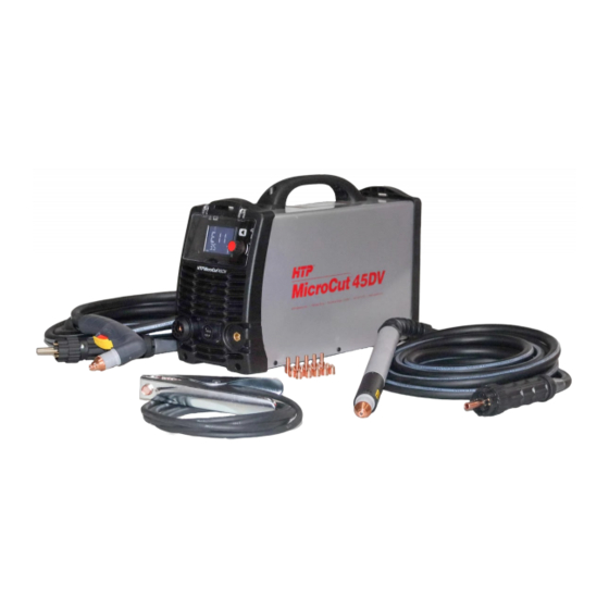
HTP MicroCut 45 DV
OPERATOR'S MANUAL
HTP America, Inc. · 180 Joey Drive · Elk Grove Village, IL 60007-1304
Phone: 847-357-0700 · Fax: 847-357-0744 · Web: www.usaweld.com
IMPORTANT: Read this Owner's Manual Completely before attempting to use this
equipment. Save this manual and keep it handy for quick reference. Pay particular
attention to the safety instructions we have provided for your protection. Contact your
distributor if you do not fully understand this manual.
Advertisement
Table of Contents

Subscribe to Our Youtube Channel
Related Manuals for HTP MicroCut 45 DV


Summary of Contents for HTP MicroCut 45 DV
- Page 1 HTP MicroCut 45 DV OPERATOR’S MANUAL HTP America, Inc. · 180 Joey Drive · Elk Grove Village, IL 60007-1304 Phone: 847-357-0700 · Fax: 847-357-0744 · Web: www.usaweld.com IMPORTANT: Read this Owner’s Manual Completely before attempting to use this equipment. Save this manual and keep it handy for quick reference. Pay particular attention to the safety instructions we have provided for your protection.
- Page 3 As a matter of general policy only, HTP may honor claims submitted by the original owner within the above times. In the case of HTP’s breach of warranty or any other duty with respect to the quality of any goods, the exclusive remedies therefore shall be, at HTP’s option, (1) repair or (2)
- Page 4 This warranty is null and void unless the warranty registration is sent to HTP America, Inc. within fifteen (15) business days from the date of purchase.
-
Page 5: Table Of Contents
Index 1 SAFETY ..............................1 2 PARAMETERS ............................. 3 2.1 P ............................3 ARAMETERS 3 INSTALLATION ..........................4 3. 1 U ............................. 4 NPACKING 3.2 I ........................4 NPUT OWER ONNECTIONS 3. 3 A ..........................4 ONNECTIONS 4 OPERATION............................4 4.1 L .................... -
Page 6: Safety
1. Safety Important Safety Precautions OPERATION AND MAINTENANCE OF PLASMA EQUIPMENT CAN BE DANGEROUS AND HAZARDOUS TO YOUR HEALTH. Plasma cutting produces intense electric and magnetic emissions that may interfere with the proper function of cardiac pacemakers, hearing aids, or other electronic health equipment. Persons who work near plasma cutting applications should consult their medical health professional and the manufacturer of the health equipment to determine whether a hazard exists. - Page 7 circuit. • Repair or replace all worn or damaged parts. • Extra care must be taken when the workplace is moist or damp. • Disconnect power source before performing any service or repairs. • Read and follow all the instructions in the Operating Manual. FIRE AND EXPLOSION Fire and explosion can be caused by hot slag, sparks, or the plasma arc.
-
Page 8: Parameters
2. Parameters 2.1 Parameters MicroCut45DV Models Parameters Normal/Grid Gouge 1-120/230V,50/60Hz Input power 1-120V 1-230V 1-120V 1-230V Rated input current(A) 20.9 20.6 Rated input power(KW) 4.47 7.03 2.30 6.18 Adjustment range of current(A) 20~25 20~45 10~25 10~45 Max no-load voltage(V) Duty cycle: (40℃,10 minutes) 25A110V 45A118V 25A145V... -
Page 9: Installation
3. Installation 3.1 Unpacking 1. Use the packing lists to identify and account for each item. 2. Inspect each item for possible shipping damage. If damage is evident, contact HTP before proceeding with the installation. 3.2 Input Power Connections Note: Check your power source for correct voltage before plugging in or connecting the unit. -
Page 10: Operation
4. Operation 4.1 Layout Of The Front And Rear Panel Figure 1. 1. LCD - Display machine status, such as the cutting current, air pressure, cutting mode, etc 2. Encoder - Adjust the cutting current and air pressure 3. Function Button - Select cutting mode, switch between first and second menu. 4. -
Page 11: Function Introduction
4.2 Function Introduction ○ ○ ○ ○ ○ ○ ○ ○ ○ ○ Figure 2. ① Check whether the cutting torch is connected ② Air pressure light ③ The machine is in working condition ④ Grid cutting mode ⑤ Normal cutting mode ⑥... - Page 12 1.Cutting mode selection Grid cutting mode: use the encoder to adjust the cutting current, press on the function button briefly to switch cutting mode. The current range is 20-45A, the air pressure range is 4.2- 5.6Bar. Normal cutting mode, use the encoder to adjust the cutting current, press on function button briefly to switch cutting mode.
- Page 13 3.Two different kinds of cutting torches Figure 8. Hand Torch Figure 9. Machine Torch 4. Alarm display...
- Page 14 Light Condition Display Status/Possible Cause Over-Current- Check output diodes, main transformer and IGBT on the invert board. Temp Over-Temperature- Stop cutting, allow machine to cool down. No system is established- Check output diodes, main transformer and IGBT on the invert board. Nozzle Repetative flashing rate of 3 No pilot arc established...
-
Page 15: Cutting Preparation
4.3 Cutting Preparation 1. Tightly connect the power cable to electrical socket outlet (the input voltage, refer to the section 2. technology parameters) 2. Connect the air line to the air supply equipment, and the ground cable to the workpiece. 3. -
Page 16: Maintenance
5. Maintenance 5.1 Cutting Torch Maintenance Warning : 1. Check the consumable parts for damage, if worn, make sure you replace the comsubales. 2. Turn off the power source before checking or removing cutting torch parts. Note: When operating the torch in a normal condition, a small amount of air vents through the gap between the shield cup and the torch handle, Do not attempt to over tighten the shield cup as irreparable damage to internal components may result. -
Page 17: Troubleshooting Principle
5.2 Troubleshooting Principle WARNING There are extremely dangerous voltage and power levels present inside this unit. Do not attempt to diagnose or repair unless you have had training in power electronics measurement and troubleshooting techniques. A. Temperature light on. 1. Fan blocked, check and correct condition. 2. - Page 18 E. Difficulty Starting 1. Worn torch parts (consumables), make sure to turn off the machine before checking the consumables. Remove and inspect torch shield cup, tip and electrode. Replace electrode or tip if worn; replace shield cup if there is excessive spatter adhering to it. F.
-
Page 19: Cutting Guidelines
6. Cutting Guidelines... -
Page 20: Consumable Breakdowns
7. Consumable Breakdowns Consumable Parts Breakdown – Hand Torch Consumable Parts Breakdown- Machine Torch... -
Page 21: Appendix
8. APPENDIX 6.1 About the HTP MicroCut 45DV Voltage Divider The MicroCut 45DV machines are equipped with an optional, factory-installed, four- position voltage divider that is designed to be safely connected without tools. The built- in voltage divider provides a scaled down arc voltage of 20:1, 21.1:1, 30:1, 40:1, and 50:1 (maximum output of 18 V). - Page 22 Torch switch signal CNC Trigger Divider output Divider Output Divider output CNC Trigger Torch switch signal Ground Transfer Arc/ Arc The cutting arc signal OK Signal connection Refer to the following table when connecting the CUT system to a torch height controller or CNC controller with a machine interface cable.
- Page 23 Note: the table below for the shift and scale selection scale selection 20:1 21.1:1 30:1 40:1 50:1 dial number...
Need help?
Do you have a question about the MicroCut 45 DV and is the answer not in the manual?
Questions and answers