Advertisement
Quick Links
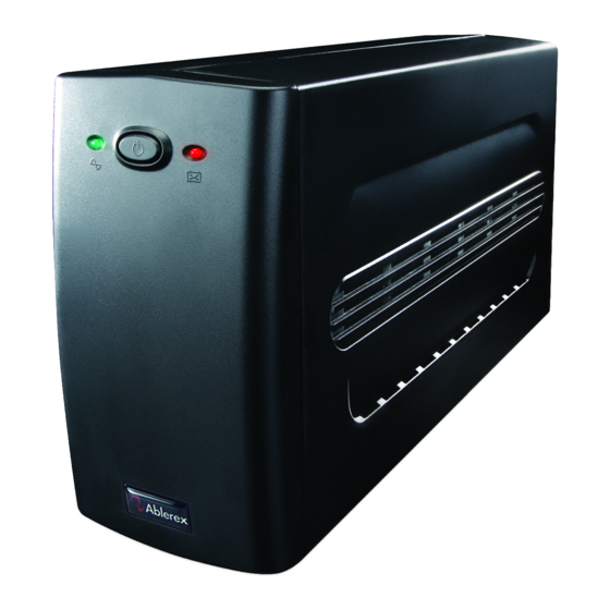
Ablerex
625L/1000L/1500L
This manual contains important safety instructions. Please follow all instructions carefully during
installation. Read this manual thoroughly before attempting to unpack, install or operate.
CAUTION
˙
To prevent the risk of fire or electric shock, install in a temperature and humidity controlled
indoor area, free of conductive contaminants.
˙
Risk of electric shock, do not remove the cover. No user serviceable parts. Refer servicing to
qualified service personnel.
˙
Risk of electric shock, hazardous live parts inside this UPS can be energized from the battery
supply even when the input AC power is disconnected.
˙
Risk of electric shock, Battery Circuit is not isolated from AC input, hazardous voltage may
exist between battery terminals and ground. Test before touching.
NOTE: The UPS is designed to be used with computer loads only.
SETUP
Step 1:Inspection
Inspect the UPS upon receipt. Notify the carrier and dealer if
there is damage. The package is recyclable; save it for reuse or
dispose off properly.
Step 2:Placement
..............................................................................................................
Step 3:Check the Site Wiring Fault Indicator (115V only)
Caution:If the site wiring fault indicator lights, get a qualified
electrician to correct the building wiring.
..................................................................
Step 4:Connect the loads
First, connect the UPS with the AC Mains, then plug the loads
into the output connectors on the rear of the UPS. To use the
UPS as a master "On/Off" switch, make sure that all of the
loads are switch "On".
Caution:Do not connect a laser printer
to the outlets. These UPS outlets provide
battery power and surge protection to the
equipment when utility voltage is outside
acceptable limits.
625VA
1000VA/ 1500VA
1000VA /
625VA
1500VA
Step 5:Connect telephone / Network Surge protection
Connect a single line telephone or a 10 base-T / 100 base-T
network cable into the RJ-45 / RJ-11 telephone / network surge
protection "IN" jack on the back of the UPS. Connect from the
"OUT" jack with telephone cable or network cabling to a fax
modem or network port.
.......................................................................................................................
Step 6:Connect Computer Interface Port (Optional)
Connect the optional interface cable to the USB interface port
on the back of the UPS. Connect to the computer.
See software document for installation instruction.
.....................................................................
Step 7:Operation Test (for Ablerex 625L)
a. Connect the UPS to the wall receptacle.
b. Push on the Main Switch to check the Green Line (
c. Connect your computer equipment with sockets of the UPS and pull off the input power cable of the
UPS from the wall receptacle to check if the Line (
Meanwhile, please check if alarm buzzer is beeping.
d. Try the field working condition by running some application programs on your computer and
repeating step.
e. Check if the UPS is initiated properly to support continuous operation.
.......................................................................................................................
Step 8:Operation Test (for Ablerex 1000L/1500L)
a. Connect the UPS to the wall receptacle.
b. Push on the Main Switch to check the Green Line (
c. Connect your computer equipment with sockets of the UPS and pull off the input power cable of the
UPS from the wall receptacle to check if the Line (
seconds. Meanwhile, please check if alarm buzzer is beeping.
d. Try the field working condition by running some application programs on your computer and
repeating step.
e. Check if the UPS is initiated properly to support continuous operation.
IMPORTANT NOTE:Plug the UPS into the wall outlet to charge the UPS for over 8 hours before using.
FRONT PANEL EXPLANATION
ABLEREX 625L
1. Line LED (
):
˙
Green LED remains standstill when Utility is normal.
˙
Green LED flashes every 3 seconds and simultaneously buzzer alarms
continuously when Utility failure.
˙
Green LED flashes every 3 seconds when the UPS is in Battery charging
Mode.
˙
Green LED remains standstill and simultaneously buzzer alarms continuously when the UPS is in
overload condition.
) LED is on.
) LED is flashing every 3 seconds.
) LED is on.
) and Inverter (
) LED are flashing every 2
1
3
2
Advertisement

Related Manuals for Ablerex 625L


Summary of Contents for Ablerex 625L
- Page 1 To prevent the risk of fire or electric shock, install in a temperature and humidity controlled …………………………………………………………… indoor area, free of conductive contaminants. Step 7:Operation Test (for Ablerex 625L) ˙ Risk of electric shock, do not remove the cover. No user serviceable parts. Refer servicing to a.
- Page 2 3. Computer Interface:True RS232 communication port. 4. RJ11/RJ45 Jacks: MODEM /LAN Protection indicator is lit. neutral wire reversal. 5. Site Wiring Fault Indicator: For 115Vac system only. Automatic Shutdown Software can be downloaded at www.ablerex.com.sg 6. USB Interface. 7. Fuse. 192321942013000...