Table of Contents
Advertisement
Instruction Manual Supplement
D103266X012
HARTr Field Device Specification
Fisher
FIELDVUE
™
Controllers
HART Revision
HART 5
. . . . . . . . . . . . . . . . . . . . . . . . . . . . . . . . .
. . . . . . . . . . . . . . . . . . . . . . . . . . . .
. . . . . . . . . . . . . . . . . . . . . . . . . .
. . . . . . . . . . . . . . . . . . . . . . . . . . . .
. . . . . . . . . . . . . . . . . . . . . . . . . . . . . . .
. . . . . . . . . . . . . . . . . . . . . . . . . . . . .
. . . . . . . . . . . . . . . . . . . . . . . . . . .
. . . . . . . . . . . . . . . . . . . . . . . . . . . .
. . . . . . . . . . . . . . . . . . . . . . . . . . . . . .
. . . . . . . . . . . . . . . . . . . . . . . . . . . .
. . . . . . . . . . . . . . . . . . . . . . . . . . . . . . .
. . . . . . . . . . . . . . . . . . . . . . . . . .
. . . . . . . . . . . . . . . . . . . . . . . . . . . . . . . .
. . . . . . . . . . . . . . . . . . . . . . . . . . . . . . . .
. . . . . . . . . . . . . . . . . . . . . . . . . . . . . . .
www.Fisher.com
DVC5000 Digital Valve
™
Device Type Device Revision Firmware Revision
02
. . . . . . . . . . . . . . . . . . . . .
. . . . . . . . . . . . . . . . . .
. . . . . . . . . . . . . . . . . . . .
. . . . . . . . . . . . . . . . . . . . . . .
. . . . . . . . . . . . . . . . .
. . . . . . . . . . . . . . . . .
. . . . . . . . . . . . . . . . . . . . . .
. . . . . . . . . . . . . . . . . . . .
. . . . . . . . . . . . . . . . . . . . . . .
. . . . . . . . . . . . . . . .
Product removed from sale October 2003
2
3
2
2
2
2
3
3
4
4
4
5
5
5
6
6
7
7
8
13
13
21
21
21
21
22
23
DVC5000 Digital Valve Controller
3, 4
5, 6
May 2018
Advertisement
Table of Contents

Related Manuals for Emerson Fisher FIELDVUE DVC5000


Summary of Contents for Emerson Fisher FIELDVUE DVC5000
-
Page 1: Table Of Contents
Instruction Manual Supplement DVC5000 Digital Valve Controller D103266X012 May 2018 HARTr Field Device Specification Fisher FIELDVUE DVC5000 Digital Valve ™ ™ Controllers HART Revision Device Type Device Revision Firmware Revision 3, 4 HART 5 5, 6 Introduction ....... . . Product Overview . -
Page 2: Introduction
This document assumes the reader is familiar with HART Protocol requirements and terminology. Additional product information is available in the DVC5000 product literature, available from your Emerson sales office or Local Business Partner. Abbreviations and definitions Alert Record Variables which represent nonvolatile values of manufacturinginitialized data or userspecified... -
Page 3: Reference Documentation
Communication Protocol, physical layers, and Data Link Layers as defined by the HART Communications Foundation. The DVC5000 is not an Active product. Contact your Emerson sales office or Local Business Partner if a copy of the instruction manual is required. -
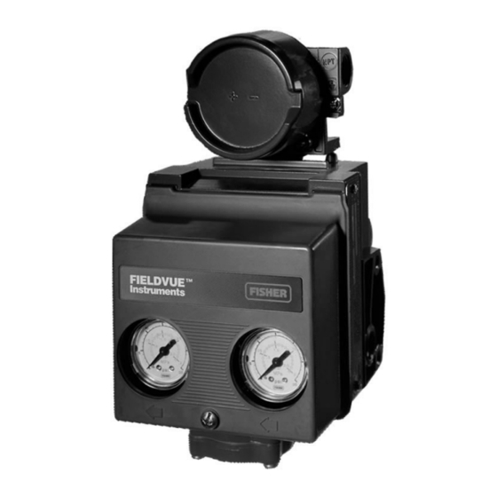
Page 4: Product Interfaces
Instruction Manual Supplement DVC5000 Digital Valve Controller May 2018 D103266X012 Product Interfaces Control Valve Interface The DVC5000 digital valve controller is mechanically attached to the valve’s actuator by means of a mounting bracket. The control valve's position is conveyed to the travel sensor of the DVC5000 digital valve controller by means of the feedback bracket attached to the actuator’s stem and the rotating travel sensor. -
Page 5: Internal Jumpers And Switches
Instruction Manual Supplement DVC5000 Digital Valve Controller D103266X012 May 2018 Internal Jumpers And Switches The input to the DVC5000 is determined by the PtPt/MultiDrop switch on the printed wiring board. LOOP- LOOP+ (MULTI‐DROP) MULTI‐DROP SWITCH AUXILIARY SWITCH DOWN (POINT-TO-POINT) A6191‐1 Refer to the DVC5000 instruction manual for additional details on the settings of the selection switches. -
Page 6: Dynamic Variables
Instruction Manual Supplement DVC5000 Digital Valve Controller May 2018 D103266X012 Dynamic Variables Four Dynamic Variables are implemented. COMMAND/RESPONSE MODE BURST MODE Default Meaning Units Default Meaning Units Analog Input mA, % Valve Travel Aux Contact Status Travel Setpoint Pressure PSI, BAR, KPA Pressure PSI, BAR, KPA FW5: Aux Status... -
Page 7: Status Information
Instruction Manual Supplement DVC5000 Digital Valve Controller D103266X012 May 2018 Status Information Device Status The Field Device Status Byte is the only status byte defined in the HART protocol. The order and meaning of each of the eight bits within the byte are fixed by the protocol. This byte is one of the status bytes included with each HART response. -
Page 8: Universal Commands
Instruction Manual Supplement DVC5000 Digital Valve Controller May 2018 D103266X012 Universal Commands The DVC5000 field device implements all HART Revision 5 Universal Commands. Command 0: Read Unique Identifier Command 1: Read Primary Variable Command 2: Read Loop Current and Percent of Range Command 3: Read Dynamic Variables and P.V. - Page 9 Instruction Manual Supplement DVC5000 Digital Valve Controller D103266X012 May 2018 Command 0: Read Unique Identifiers Byte Description Format Value Request none Data Bytes Data type expansion code Byte, hex Manufacturer identification code Byte, hex Manufacturer’s Device Type code Byte, hex Number of preambles Byte, hex Universal command revision...
- Page 10 Instruction Manual Supplement DVC5000 Digital Valve Controller May 2018 D103266X012 Command 1: Read Primary Variable This command reads the value of the DVC5000’s measured Valve Travel. The units are “%”. Byte Format Description Request none Data Bytes Byte, hex Valve Travel Unit Code, 57(%) Response 14 Float...
- Page 11 Instruction Manual Supplement DVC5000 Digital Valve Controller D103266X012 May 2018 Command 3: Read Dynamic Variables and Loop Current This command is used to read the value of Loop Current and the four Dynamic Variables. The default Dynamic Variable assignment and the Variable Units Codes are shown on page 6. Byte Format Description...
- Page 12 Instruction Manual Supplement DVC5000 Digital Valve Controller May 2018 D103266X012 Command 15: Read Primary Variable Output Information This command returns the upper/lower range values for the measured Valve Travel. The range values can be changed via Command 35. Byte Format Description Returned Value Request...
-
Page 13: Commonpractice Commands
Instruction Manual Supplement DVC5000 Digital Valve Controller D103266X012 May 2018 CommonPractice Commands The DVC5000 field device supports the following common practice commands: Supported Commands Command 33: Read Device Variables Command 35: Write Primary Variable Range Values Command 38: Reset Configuration Change Flag Command 42: Master Reset Command 48: Read Additional Status Command 50: Read Dynamic Variable Assignments*... - Page 14 Instruction Manual Supplement DVC5000 Digital Valve Controller May 2018 D103266X012 Command 35: Write Primary Variable Range Values In the DVC5000, the Primary Variable is defined to be the measured Valve Travel. This command is used to write the ranging values reported in Command 15. It sets the engineering units to be reported with 0% and 100% of calibrated travel.
- Page 15 Instruction Manual Supplement DVC5000 Digital Valve Controller D103266X012 May 2018 Command 42: Perform Master Reset Responds immediately by performing a “warm” reset. This is not equivalent to power up in that restart modes and default IVP are not adopted and the realtime clock is not reset. All other data is read from nonvolatile memory and put into effect.
- Page 16 Instruction Manual Supplement DVC5000 Digital Valve Controller May 2018 D103266X012 Additional Device Status— DVC5000 Device Revision 2, Firmware 3, 4 Command 48 returns 5 bytes of data, with the following status information: Byte Name of Status Bit Meaning Reserved Active if the microprocessor detects a fault in the servo execution No Free Time period.
- Page 17 Instruction Manual Supplement DVC5000 Digital Valve Controller D103266X012 May 2018 Additional Device Status— DVC5000 Device Revision 2, Firmware 3, 4 (continued) Byte Name of Status Bit Meaning Reserved Reserved Reserved Reserved Reserved Reserved Reserved Reserved Travel Alert Lo Active when the Travel is below the Travel Alert Lo Point. Travel Alert Lo Lo Active when the Travel is below the Travel Alert Lo Lo Point.
- Page 18 Instruction Manual Supplement DVC5000 Digital Valve Controller May 2018 D103266X012 Additional Device Status - DVC5000 Device Revision 3, Firmware 5, 6 Command 48 returns 7 bytes of data, with the following status information: Byte Name of Status Bit Meaning Reserved Active if the microprocessor detects a fault in the servo execution No Free Time period.
- Page 19 Instruction Manual Supplement DVC5000 Digital Valve Controller D103266X012 May 2018 Additional Device Status - DVC5000 Device Revision 3, Firmware 5, 6 (continued) Byte Name of Status Bit Meaning Reserved Reserved Reserved Reserved Reserved Reserved Reserved Reserved Travel Alert Lo Active when the Travel is below the Travel Alert Lo Point. Travel Alert Lo Lo Active when the Travel is below the Travel Alert Lo Lo Point.
- Page 20 Instruction Manual Supplement DVC5000 Digital Valve Controller May 2018 D103266X012 Command 50: Read Dynamic Variable Assignments This command returns a list of four device variable codes taken from table DVC Device Variables which are returned in Command 3. Byte Format Description Request None...
-
Page 21: Device-Specific Commands
Device Revision 2 of this field device does not support Burst Mode. Catch Device Variable This field device does not support Catch Device Variable. Performance Refer to the instruction manual, available from your Emerson sales office or Local Business Partner. -
Page 22: Annex A Compatibility Checklist
Instruction Manual Supplement DVC5000 Digital Valve Controller May 2018 D103266X012 Annex A Compatibility Checklist Manufacturer, Model, and Revision Fisher Controls DVC5000 Device Revision 2 and 3 Device Type Pneumatic Control Valve Positioner HART Protocol Revision User switchable between HART 5 mode and HART 7 mode? Device Description Available? Number and type of process connections... -
Page 23: Annex B Dvc5000 Parameters As Part Of A Rosemountr 1410/1420 Wirelesshartr Gateway
Instruction Manual Supplement DVC5000 Digital Valve Controller D103266X012 May 2018 Annex B DVC5000 Parameters as part of a Rosemount 1410 / 1420 WirelessHART Gateway A FIELDVUE DVC5000 can join a wireless network through the addition of a Rosemount 775 THUM WirelessHART adapter. - Page 24 Instruction Manual Supplement DVC5000 Digital Valve Controller May 2018 D103266X012 The FIELDVUE instrument is defined on the Gateway by “Tag” (read from the device’s “Message” field). For each Tag, the Gateway provides updated values for: D Variables D Additional Status D Published Data...
- Page 25 Instruction Manual Supplement DVC5000 Digital Valve Controller D103266X012 May 2018 Published Data, used for the Gateway’s OPC and Modbus outputs, falls into the following categories: Field Device Identification Values: Values that define the identity of the DVC5000. These include: D MANUFACTURER (for “Fisher Controls” the value is “19”) D DEVICE_TYPE (for a DVC5000 the value is “2”) D DEVICE_REVISION D HARDWARE_REVISION...
- Page 26 Instruction Manual Supplement DVC5000 Digital Valve Controller May 2018 D103266X012 Either of these choices (Dynamic Variable or Device Variable ID) can be substituted for the “#” sign in the Variable Identifier fields below. Variable Identifier Comments / Explanation See any of the variable identifiers in the table immediately above. #_CLASS Always “0”.
- Page 27 Instruction Manual Supplement DVC5000 Digital Valve Controller D103266X012 May 2018 Detailed Device Alerts: The Alert Groupings are: D ADDITIONAL_STATUS_0 D ADDITIONAL_STATUS_1 D ADDITIONAL_STATUS_2 D ADDITIONAL_STATUS_3 D ADDITIONAL_STATUS_4 D ADDITIONAL_STATUS_5* D ADDITIONAL_STATUS_6* ADDITIONAL_STATUS_5 and ADDITIONAL_STATUS_6 are supported in Device Revision 3 only Each of these status bytes represent eight individual bits with values that range from “00” to “255”. To determine which of the eight bits are active requires converting a decimal value to its binary equivalent value.
-
Page 28: D103266X012 May
Responsibility for proper selection, use, and maintenance of any product remains solely with the purchaser and end user. Fisher, FIELDVUE, and ValveLink are marks owned by one of the companies in the Emerson Automation Solutions business unit of Emerson Electric Co.
Need help?
Do you have a question about the Fisher FIELDVUE DVC5000 and is the answer not in the manual?
Questions and answers