Table of Contents
Advertisement
Advertisement
Table of Contents

Related Manuals for Mastech MS8212A


Summary of Contents for Mastech MS8212A
- Page 1 MS8212A Pen-type Digital Multimeter Manual CAT III 600V...
-
Page 2: Table Of Contents
CONTENTS CONTENTS Safety Information.........1 ......... 4.5 Auto Power Off ....4.6 Preparing for Measurement 1.1 Preparing for use ........1 ................1.2 During Use 4.7 DC Voltage ..... -
Page 3: Safety Information
1.2 During Use 1.Safety Information 1.2.1 Always make sure the rotary switch is at the correct function and range. WARNING 1.2.2 Do not exceed the protection limit values indicated To reduce the risk of fire, electrical shock, product for each function damage or personal injury, please follow the 1.2.3 Do not touch test lead tips while connected to a safety instructions described in the user manual. -
Page 4: Safety Symbols
1.4 Maintenance 1.3 Safety Symbols 1.4.1 Repairs should only be implemented by trained Important safety information.See manual personnel. for details. 1.4.2 Remove test leads from measurement circuits Equipment protected throughout by double before opening the battery cover. insulation or reinforced insulation. 1.4.3 In order to avoid incorrect readings that may cause MEASUREMENT CATEGORY III is applicable damage or personal injury, replace batteries as... -
Page 5: Front Panel
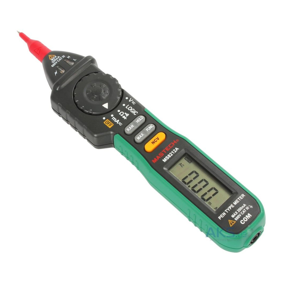
2.2 Buttons and Functions 2.1 Front Panel - Function Buttons 1.Positive test probe (+) 2.Probe cover (removable) Button Function Description 3.NCV Indicator Any switch This Button is used to hold data. 4.LED indicators position HOLD Disables automatic power-off 5.Protective ring Power-up Option feature. -
Page 6: Specifications
3.2 Technical Specifications 3. Specifications Accuracy is specified for a period of year after calibration (ambient temperature: 23±5°C, relative humidity <75%) and at 18°C to 28°C(64°F to 82°F)with relative humidity 3.2.1 DC Voltage to 75%. Measuring Range Resolution Accuracy 3.1 General specifications 200mV 0.1mV •... - Page 7 3.2.3 Resistance 3.2.6 DC Current Measuring Range Resolution Accuracy Measuring Range Resolution Accuracy ±(1.0% reading + 3dgt) 200Ω 0.1Ω 20mA 0.01mA ±(1.5% rdg + 3dgt) 2kΩ 0.001kΩ 200mA 0.1mA 20kΩ 0.01kΩ -Overload protection: resettable fuse ±(1.0% reading + 1dgt) 200kΩ 0.1kΩ...
-
Page 8: Using The Meter
4. Using the Meter 4.5.3 If you hold down the “HOLD” button when turning on the meter, this will disable the auto power off 4.1 Reading Hold function.The auto power off function will re-enable 4.1.1 During measurement, press the “HOLD” button to after the meter is turned off again. -
Page 9: Ac Voltage
4.8 AC Voltage WARNING To prevent electric shock and damage to the meter or personal injury, do not measure voltages that may exceed 600V AC rms. 4.8.1 Use the probe cover if making measurements on category III installations. 4.8.2 Insert the black test lead into the COM jack. 4.8.3 Turn the rotary switch to the position. -
Page 10: Resistance
Note: - Before connecting the probe and test lead at lower voltage ranges, the display may show erratic readings. This is normal because the meter is highly sensitive. Once a connection is made, the true reading will be displayed. - “OL” indicated an over-range situation in manual mode. A higher range should be selected. -
Page 11: Continuity
Note: Note: - If the leads are not connected or the resistance is higher - The display shows the approx. forward voltage drop. than 200Ω, the display will show “OL”. - If the connections are reversed or the leads are not 4.12 DC Current connected, the display will show “OL”. -
Page 12: Ac Current
4.13 AC Current 4.14.4 Connect the black test lead to the circuit’s ground (-) terminal. WARNING 4.14.5 Hold down the “FUNC” button and touch the test Risk of electric shock. never measure current probe to the circuit for measurement. The LEDs where open circuit voltages exceed 250V to near the tip of the meter will indicate the current prevent damage to the meter or personal injury. -
Page 13: Maintenance
If the test lead’s insulation is damaged or has any wires exposed, the leads need to be replaced. WARNING Use meet EN 61010-031 standard, rated CA T III 600V, or better test leads. DONGGUAN HUANGYI MASTECH COMPANY LIMITED 72 Puxing East Road Qingxi,Dongguan,Guangdong,China. Tel:+86-769-8190-1688 Fax:+86-769-8190-1600 http://www.p-mastech.com info@p-mastech.com...
Need help?
Do you have a question about the MS8212A and is the answer not in the manual?
Questions and answers