Table of Contents

Related Manuals for Mastech MS8240D


Summary of Contents for Mastech MS8240D
-
Page 1: Table Of Contents
Table of Contents 1. Introduction 2. Safety note 3. Explanation of Controls and Indicators Digital Multi Meter 3-1. Product illustration 3-2. Functional push button 3-3. LCD display OPERATING INSTRUCTION 4. Specification 4-1. General Feature 4-2. Electrical Specification 5. Measurement operation 5-1. -
Page 2: 2. Safety Note
● Do not measure current with test lead inserted into voltage or OHM drop. The MS8240D are a high performance, low power consumption and 4 1/2 digits terminal. ● Do not expose the instrument to the direct sun light, extreme temperature (22000 counts) With 46 segments bar graph. -
Page 3: 3. Explanation Of Controls And Indicators
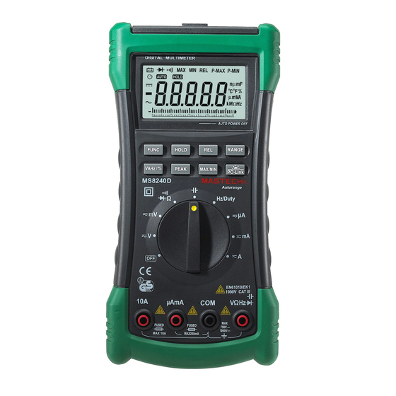
- 5 - 3. Explanation of controls and indicators Note international Electrical Symbol. 3-1. Meter illustration Dangerous Voltage Ground AC (Alternating Warning see current) explain in manual DC (Direct Current) Double insulation AC or DC Fuse Measurement category(over voltage category): This instrument is meet the safety condition of CAT III. -
Page 4: Functional Push Button
⑨ “PEAK” push button Makes the meter stop updating the maximum or the minimum ⑾ Rotary Switch(Knob) value. ⑿ Input terminal It is the auto/manual measurement push key that act with ⒀ “COM”terminal trigger. The default is auto measurement when power is on. ⒁... - Page 5 Duty cycle range is within 5.0% to 94.9%. If the source frequency duty Minimum value cycle is smaller than 5.0%, the ‘UL’ sign will be shown on the LCD HOLD Data hold display, and then if the duty cycle is larger than 94.9%, the ‘OL’ sign Pmax, Pnin Maximum peak value will be shown on the LCD display.
-
Page 6: General Feature
● MAX/MIN value measurement function ● AUTO/MANUAL Mode selection ● Back Light ● Low battery indication ● True- RMS measurement for AC voltage / AC current measurement ● Relative value measurement function ● USB interface for communication to the computer. ●... -
Page 7: Electrical Specification
○ 4-2. Electrical Specification Continuity Buzzer sounds Open circuit voltage: Check at less than about 2.7V Function Range Best. Accuracy Over Load 30Ω Resolution Protection Diode Testing Current: Open circuit voltage: ± ○ DC Voltage 2.2/22/220/1000V 0.1mV Check About 1.5mA about 2.7V (0.05%rdg+3dgt)... -
Page 8: Resistance Measurement
Note: Current 1 includes Auto uA, Auto mA, 10A mode. Current 2 includes Manual 2.2A, 10A mode. 5-2. Resistance measuremen The resistance range are: 220.00Ω 2.2000KΩ,22.000KΩ, 220.000KΩ , 5-2. DC & AC voltage measurement 2.2000MΩ. 22.000MΩ and 220.0MΩ( Note: it is not 220.00MΩ to prevent the Warning least digit from jumping). -
Page 9: Capacitance Measurement
- 19 - - 18 - several second to obtain stable reading. 5-4. Capacitance measurement The LCD display OL indicating open-circuit for the tested resistor or Warning: the resistor value is higher than the maximum range of the meter. 5-3. -
Page 10: Frequency & Duty Cycle Measurement
- 20 - - 21 - 3. test lead into the “ NOTE: COM” terminal. [1] You can used the MS3202 Socket according to the capacitor pin size. 4. Connect the test leads across with the circuit under testing. The . -
Page 11: Dc/Ac 10A Measurement
- 22 - - 23 - 4. more positive side of the break and the black test lead to the more 6. Maintenance negative side of the break. 5. Turn on power to the circuit. The measured value show on the display. 6-1. -
Page 12: Cleaning And Decontamination
In this meter used special USB cable with A type USB connector and mini-USB connector. 7-2. Installation of application software First you must be install the <USB –RS232 Driver> & < MS8240D USB Program>. The install process is automotive. First, insert the CD to the CD driver of PC. - Page 13 -26 – - 27 - 6:First, execute the file: \\PCLink 7:Select the communication port from the <ComSelect> menu. You are multimeter\multimeter.exe , so that wll display must be Select the COM4. Following dialog window. 8: Power on the DMM and then push the “PC-Link”button more than 3secs to inert to the Communication mode.
- Page 14 - 28 - - 29 - Click the <Connect> key on the screen . The measured data will be *** Note: displayed on the screen of PC as following screen. If communication is failed,should be adjusting the interval betwee infrared light emitting diode...
Need help?
Do you have a question about the MS8240D and is the answer not in the manual?
Questions and answers