Table of Contents
Advertisement
Quick Links
Advertisement
Table of Contents

Related Manuals for Mastech MS8332C


Summary of Contents for Mastech MS8332C
- Page 1 MS8332C Digital Multimeter User Manual CAT III 600 V...
-
Page 2: Table Of Contents
CONTENTS CONTENTS 5.3 Diode Measurement ........11 1. Introduction..........1 5.4 Continuity Measurement ......11 2. Safety Information........2 5.5 Capacitance Measurement......12 3. Product Overview.........3 5.6 Frequency Measurement ......13 ......Product External View 5.7 Duty Cycle Measurement ......13 3.2 Function Keys..........4 5.8 Current Measurement .......13 3.3 Symbols..........4 ......... -
Page 3: Introduction
2. Safety Information 1.Introduction The digital multimeter is designed and manufactured Warning according to safety requirements of EN 61010-1, The special attention should be paid when using EN 61010-2-030, EN 61010-2-033, EN 61010-031 on the meter because the improper usage may cause electronic measuring instrument and hand held digital electric shock and damage the meter .The safety multipurpose meter. -
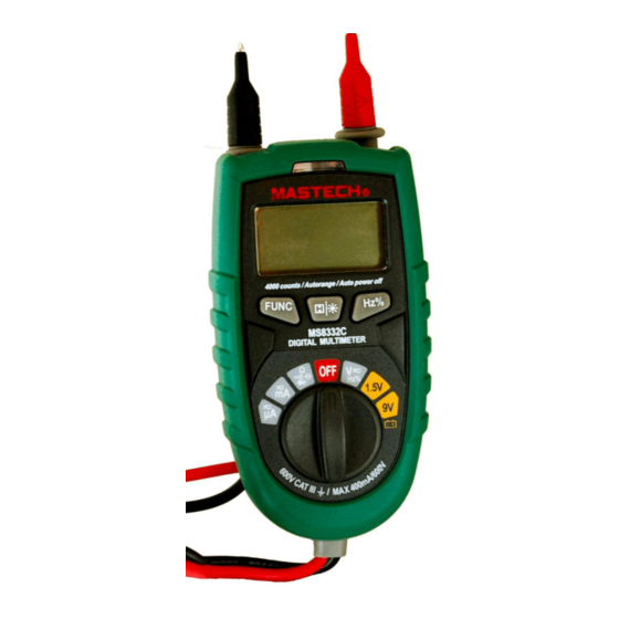
Page 4: Product Overview
3. Product Overview 3.2 Function Keys 3.1 Product External View Function Switching Key, The voltage current range is used for switching AC/DC mode,the resistance rangeis used for switching mode. Switching key between frequency and duty cycle, it is used for switching Hz and % at voltage range and current range. -
Page 5: Technical Index
4.2.2 AC Voltage 4 Technical Index 4.1 General Characteristics Measuring Range Resolution Accuracy • Automatic measuring range is DMM, full range is 3999 counting. • Display: 3 3/4 digits LCD display. ±(0.8% rdg + 3dgt) 10mV • Overload protection: full range protection. 400V 100mV •... - Page 6 4.2.4 Diode, Continuity 4.2.7 Capacitance Measuring Range Function Measuring Range Resolution Accuracy ± (5 0% rdg +30dgt) 40nF 0.01nF Display forward voltage drop of diode ± (3 0% rdg +15dgt) 400nF 0.1nF The buzzer makes a sound when the resistance is less than 50±20Ω Open Circuit Voltage: diode is about 1.5V, buzzer is about 0.5V.
-
Page 7: Measuring Operations
5. Measuring Operations 5.2 Resistance Measurement 5.1 AC Voltage and DC Voltage Measurement Warning Warning In order to avoid the meter or measured equipment from being damaged,cut off all power supply of 1.To avoid electricial shock or meter damage, any measured circuits and discharge all high voltage voltage in excess of 600V DC or r.m.s AC are not capacitors before measuring capacitance. -
Page 8: Diode Measurement
5.3 Diode Measurement 3.Separately connect two ends of test leads to the two ends of measured part and circuit. Warning 4.The meter shall display the approximate resistance value between measured points.Here if the resistance To avoid the meter or measured equipment from value between measured points is less than 50±20Ω, being damaged, cut off all power supply of the buzzer will make a sound. -
Page 9: Frequency Measurement
5.6 Frequency Measurement 2.Turn rotary switch to mA or uA position.When the measured current is less than 400uA, select uA The method of measuring frequency is: position.When the measured current is 4mA~400mA, 1.Turn rotary switch Hz% to position. select mA position. 2.Press Hz% key and select Hz range. -
Page 10: Maintenance
6. Maintenance 6.1.4 Put the battery cover back and fix it again to its origin form. • Before removing the rear cover, disconnect the probe from Note: the circuit to be measured. • To protect the internal circuit, replace the fuse with one of Do not reverse the polarity of the batteries.
Need help?
Do you have a question about the MS8332C and is the answer not in the manual?
Questions and answers