Advertisement
Quick Links
8
4
20
1
10
5
9
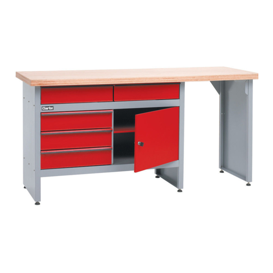
Contents
1.
Left Leg x 1
2.
Middle Leg x 1
3.
Door x 1
4.
Upper Panel x 1
5.
Bottom Panel x 1
6.
Cross Panel x 1
7.
Back Panel x 1
8.
Bench Top x 1
9.
Drawer Runner (Type 'B') x 3
10. Drawer Runner (Type 'C') x 3
11. Foot x 6
12. Screw M8x40 x 6
13. Nut M8 x 6
14. Drawer Front x 5
15. Drawer Bottom x 5
16. L/H Drawer Side x 10
Please note that the details and specifications contained herein are correct at the time of going to print. However
CLARKE International reserve the right to change specifications at any time without prior notice.
CWB1700P
Part Number: 4501510
Assembly Instructions
21
7
6
19
22
25
24
23
2
,
,
11
12
13
3
16
14
18. Drawer Back x 5
19. Shelf x 1
20. Drawer Runner (Type 'A') L/H x 2
21. Drawer Runner (Type 'A') R/H x 2
22. Door Lock x 1
23. Right Leg x 1
24. Front Angle Bracket x 1
25. Rear Bracket x 1
Polythene bag containing nuts, screws
and washers etc.
'A'
'B'
'C'
18
15
16
0807
Advertisement

Related Manuals for Clarke CWB1700P


Summary of Contents for Clarke CWB1700P
- Page 1 16. L/H Drawer Side x 10 and washers etc. Please note that the details and specifications contained herein are correct at the time of going to print. However CLARKE International reserve the right to change specifications at any time without prior notice. 0807...
- Page 2 ALWAYS keep work area clean and free from oil spills etc. ASSEMBLY Before attempting to assemble the work bench, carefully unpack/unwrap and lay out all components, check off against the list of contents on front page, notify your Clarke dealer ASAP of any shortages and/or damage. Tools required: Cordless drill and drill bits (4mm and 5mm).
- Page 3 To ensure the assembly is as square as possible before continuing, position the bench where it is to be sited. Place spirit level on the upper panel and adjust the feet until the unit is level in both directions, i.e. front to back and side to side, secure with locking nuts. Once satisfied the unit is as square as possible, proceed to tighten all screws and nuts, starting in the centre and working outwards until all are tight, DO NOT overtighten.
- Page 4 Line up the hole in the rail with the hole at the front of the drawer and secure with countersunk screw, nut and lockwasher. NOTE: countersunk screw must be fitted from inside the rail with the nut and lockwasher inside the drawer. Once both drawers are fitted and secured, tighten all woodscrews securing drawer runners to the bench top.