Table of Contents
Advertisement
Quick Links
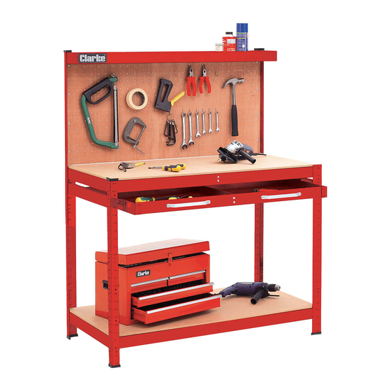
WORKBENCH WITH BACK PANEL &
DRAWER
MODEL NO: CWBR1B & CWBG1B
PART NO: 7637706 & 7637707
Assembly INSTRUCTIONS
ORIGINAL INSTRUCTIONS
GC0319 - ISS 1
Advertisement
Table of Contents

Related Manuals for Clarke CWBR1B


Summary of Contents for Clarke CWBR1B
- Page 1 WORKBENCH WITH BACK PANEL & DRAWER MODEL NO: CWBR1B & CWBG1B PART NO: 7637706 & 7637707 ASSEMBLY INSTRUCTIONS ORIGINAL INSTRUCTIONS GC0319 - ISS 1...
- Page 2 All components have identifying stickers that correspond with the component parts list. Should any part be damaged or missing, please contact your Clarke dealer immediately for replacement. Parts & Service: 020 8988 7400 / E-mail: Parts@clarkeinternational.com or Service@clarkeinternational.com...
- Page 3 COMPONENT PARTS Item Description Front Leg Post Left Rear Post Right Rear Post Drawer Mounting Beam (Left) Drawer Mounting Beam (Right) Side Beam Long Beam Left Upper Post Right Upper Post Top Long Beam Top Left Side Beam Top Right Side Beam Drawer Front Panel Drawer Rear Panel Drawer Side Panel...
- Page 4 ASSEMBLY All fixing bolts should be entered from the outside and secured on the inside by the washers and nuts provided. Assembly should be carried out with all nuts finger tight only - DO NOT tighten the nuts until the structure is fully assembled as described in the instructions. Assembly may be easier with the help of a second person.
- Page 5 4. Fit the long beams (G) at the top of the corner posts to create the main frame using further bolts, washers & nuts. 5. BoIt the left/right upper post (H & I) to the rear posts as shown using further bolts, washers &...
- Page 6 6. Attach one top long beam (J) to the rear surface of the post extensions using further bolts, washers & nuts. 7. Assemble the remaining top long beam (J) to the left/right top side beams (K/ 8. Bolt this assembly to the side faces of the post extensions complete the frame.
- Page 7 ASSEMBLE & FIT THE DRAWER 1. Assemble the side panels (P), rear panel (O) and front panel (M) of the drawer using bolts, washers and nuts as shown. 2. Rest the drawer bottom (Q) into the drawer frame. 3. Attach the handles (7) to the sliding drawer using four bolts (4) and nuts (8).
- Page 8 FIT THE WORKTOP PANELS 1. Fit the worktop panel (T) by placing it onto the frame and tapping it into position. 2. Fit the bottom shelf (S) by sliding it in from the side at an angle and resting it in position.
Need help?
Do you have a question about the CWBR1B and is the answer not in the manual?
Questions and answers