Tait TB9100 Installation And Operation Manual
Console gateway
Hide thumbs
Also See for TB9100:
- Installation and operation manual (170 pages) ,
- Service manual (132 pages) ,
- Operation manual (54 pages)

Subscribe to Our Youtube Channel
Related Manuals for Tait TB9100


Summary of Contents for Tait TB9100
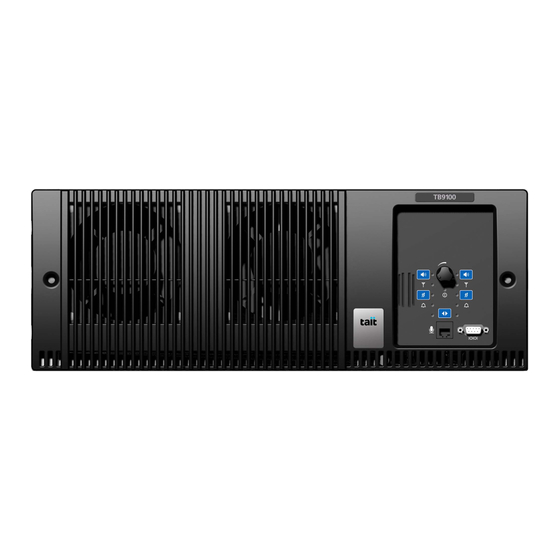
- Page 1 TB9100 base station P25 CG console gateway Installation and Operation Manual MBA-00002-07 Issue 7 January 2007...
-
Page 2: Contact Information
Limited. Digital Voice Systems, Inc. This voice coding The word TAIT and the TAIT logo are trademarks of Technology is licensed solely for use within this Tait Electronics Limited. Communications Equipment. The user of this... -
Page 3: Table Of Contents
Proximity to RF Transmissions........28 TB9100/P25 CG Installation and Operation Manual... - Page 4 Connecting the Analog Line ........58 TB9100/P25 CG Installation and Operation Manual...
- Page 5 Digital Interface Connection ........121 TB9100/P25 CG Installation and Operation Manual...
- Page 6 TaitNet P25 Glossary ........131 TB9100/P25 CG Installation and Operation Manual...
-
Page 7: Preface
Associated Documentation The current set of TB9100 product documentation is provided in PDF format on the product CD. Updates are made available on the Tait support web. Print copies of the documentation are available on request. TB9100/P25 CG Installation and Operation Manual... -
Page 8: Publication Record
■ Technical notes are published from time to time to describe applications for Tait products, to provide technical details not included in manuals, and to offer solutions for any problems that arise. The product CD includes technical notes that were available at the time of release. Look for new or updated technical notes on Tait’s technical support website. -
Page 9: Description
P25 modes, to link stations using standard Internet Protocol communications, and to add features through software options ensures that P25 systems designed with the TB9100 are scalable in both size and functionality. The TB9100 base station and P25 Console Gateway combine industry- leading digital voice quality with rugged design specifications and intuitive user interfaces. -
Page 10: Features
Features The following are some of the features of the TB9100 base station: Fully compliant with the Project 25 Common Air Interface. Can ■ therefore interoperate with any similarly compliant radios. Dual mode. Comprehensive analog and digital features ensure ■... -
Page 11: Modules
Receive-only base stations and P25 Console Gateways do not need PAs. Each module is inserted into the TB9100 4U subrack from the front and is secured at the front with a metal clamp. Both clamp and module are easily removed for rapid module replacement. -
Page 12: Base Station Reciter
Only the gateway module in position 1 can communicate with the PMU (if fitted). It is not possible to convert a gateway module into a reciter. Description TB9100/P25 CG Installation and Operation Manual © Tait Electronics Limited January 2007... -
Page 13: Power Amplifier
100W PA All three models are designed to operate on the 28VDC output provided by the TB9100 power management unit. In addition, variants of the 5W and 50W models are available for DC-only operation. These two 12V PAs are fitted with an internal boost regulator board, which converts the 12V nominal DC input to a 28VDC output to power the PA circuit boards. -
Page 14: Front Panel
The position of a module in the rack is defined by the socket in the subrack interconnect board to which the module is connected by the system control bus. Description TB9100/P25 CG Installation and Operation Manual © Tait Electronics Limited January 2007... -
Page 15: Frequency Bands And Sub-Bands
Receive: 792MHz to 824MHz Base Station Options The modular design of the TB9100 base station means that it is available in many variations. A range of features that can be enabled in software adds another level of configurability. Here are some of the different products that result from different module combinations. -
Page 16: Receive-Only Base Station
Base Station Applications TB9100 base stations can be used as repeaters or as base stations. They can be connected together as a channel group, to form a wide area repeater or wide area base station. They can be used in trunking systems and in conventional systems with analog or digital dispatch equipment. -
Page 17: Line-Connected Base Station
P25 Linking A pair of TB9100 base stations can function as linking transceivers and be used to provide an RF link, for example between a channel group and a base station at a remote site. -
Page 18: Theory Of Operation
The reciter carries out signal processing and has overall control of the base station. It comprises an RF, a digital, and a network board, as shown in Figure 1.3. Description TB9100/P25 CG Installation and Operation Manual © Tait Electronics Limited January 2007... - Page 19 TaitNet P25 Network, and gives the base station an identity as a network element. It also provides the physical connections for the Ethernet, analog and RS-232 serial interfaces. For more detailed information, see “Technical Description” on page TB9100/P25 CG Installation and Operation Manual Description © Tait Electronics Limited January 2007...
-
Page 20: Signal Paths
RF interface (via the digital board), for transmitting P25 over the ■ air) Ethernet interface (via the IP protocol stack), for sending to the ■ other channel group members Description TB9100/P25 CG Installation and Operation Manual © Tait Electronics Limited January 2007... -
Page 21: Run And Standby Modes
FM or digital P25, depending on the input. When the base station receives an input on an interface, it operates in the mode of that input. TB9100/P25 CG Installation and Operation Manual Description © Tait Electronics Limited January 2007... - Page 22 FM mode using the microphone button. Refer to “Microphone Operation” on page 64 further details. The destination of the signal is configured by the CSS. Description TB9100/P25 CG Installation and Operation Manual © Tait Electronics Limited January 2007...
-
Page 23: Intermodule Communications
Figure 1.5. Figure 1.5 Intermodule communication paths Reciter μP μP μP I C Current Source Control Panel Microphone Speaker User Controls Subrack Interconnect Board TB9100/P25 CG Installation and Operation Manual Description © Tait Electronics Limited January 2007... -
Page 24: Power Management
A range of parameters is monitored and can trigger alarms that are sent via the reciter to the CSS and a syslog collector. When the PMU has an AC and a DC module, the TB9100 can be powered AC to DC Changeover by either the AC (mains) or the DC (battery) supply. - Page 25 DC terminal at rear of subrack Boost Aux. DC Regulator J17 connector on subrack inter- connect board Reciter Reciter Reciter 10.8 - 32V Control Control Control Panel Panel Panel TB9100/P25 CG Installation and Operation Manual Description © Tait Electronics Limited January 2007...
-
Page 26: Front Panel Fans
PMU temperature, as follows: PMU Temperature Duty Cycle <149°F (65°C) Increases with increasing current draw 149-167°F (65-75°C) On two minutes, off one minute >167°F (75°C) Always on Description TB9100/P25 CG Installation and Operation Manual © Tait Electronics Limited January 2007... -
Page 27: General Safety And Regulatory Information
Refer to the ratings label on the rear of the module. The TB9100 base station must be installed so that the rear of the PMU is located in a service access area. The PMU must be connected to the mains supply source by trained personnel in accordance with local and national regulations. -
Page 28: Explosive Environments
Tait Dealer or Customer Service Organization immediately. All servicing should be carried out only when the PMU is powered through a mains isolating transformer of sufficient rating. We strongly recommend that the mains power to the whole of the repair and test area is supplied via an earth leakage circuit breaker. -
Page 29: Esd Precautions
The seals must be difficult to reproduce. A sticker initialed or signed by the technician should satisfy this. Seals must be replaced if they need to be disturbed during maintenance. TB9100/P25 CG Installation and Operation Manual General Safety and Regulatory Information © Tait Electronics Limited January 2007... -
Page 30: Environmental Conditions
Environmental Conditions Operating Temperature Range The operating temperature range of the TB9100 is –22°F to +140°F (–30°C to +60°C) ambient temperature. Ambient temperature is defined as the temperature of the air at the intake to the cooling fans. Humidity The humidity should not exceed 95% relative humidity through the specified operating temperature range. -
Page 31: Unauthorized Modifications
If trouble is experienced with the XBA1PA0 Network Board in the Reciter, for repair or warranty information, please contact your local Tait Dealer or Customer Service Organization. Only approved Tait Dealer or Customer Service Organizations equipped with the necessary facilities should perform any servicing. - Page 32 Declaration of Conformity eudocs.taitworld.com/. You can also obtain a signed and dated paper copy of the Declaration of Conformity from Tait Europe Ltd. General Safety and Regulatory Information TB9100/P25 CG Installation and Operation Manual © Tait Electronics Limited January 2007...
-
Page 33: Installation
19inch rack or cabinet. If this is your first time installing a TB9100 base station, we recommend that you read the entire chapter before beginning the actual installation. -
Page 34: Equipment Ventilation
Cabinet and Rack Ventilation The cooling airflow for the TB9100 base station enters through the front panel and exits at the rear of the subrack. For optimum thermal performance, the heated air that has passed through a base station must not be allowed to re-enter the air intakes on the front panel. - Page 35 38U cabinet is five, as shown in Figure 3.1 on page If the TB9100 base station is installed in a rack or cabinet with other equipment with different ventilation requirements, we recommend that the TB9100 be positioned below this equipment.
- Page 36 Figure 3.1 Typical cabinet ventilation requirements top view (20cm) side view front view ≥7in (≥17.5cm) ventilation slots airflow entry blanking panels airflow exit Installation TB9100/P25 CG Installation and Operation Manual © Tait Electronics Limited January 2007...
-
Page 37: Installing And Setting Up The Css
Installing and Setting up the CSS To monitor and configure the base station, and to carry diagnostic tests on it, you need the CSS. Follow the instructions on the TB9100 CSS CD and install the CSS on a PC. To install the CSS, you need a registration key. You can obtain a key from Tait. -
Page 38: Minimum Pc Requirements For Running A Css
■ Unpacking and Moving the Base Station The TB9100 base station is packed in a strong corrugated cardboard carton with top and bottom foam cushions. To prevent personal injury and damage to the equipment, we recommend that two people unpack and move the base station. - Page 39 The foam cushions are CFC- and HCFC-free and may be burnt in a suitable waste-to-energy combustion facility, or compacted in landfill. TB9100/P25 CG Installation and Operation Manual Installation © Tait Electronics Limited January 2007...
-
Page 40: Setting Up On The Bench
10-32 VDC Power Supply Reciter rear DC input connector 9-way digital I/O / serial connector RJ-45 Ethernet RJ-45 9-way port (male) Analog RJ-45 (audio) 3-wire cable (TXD,RXD,GRND) Installation TB9100/P25 CG Installation and Operation Manual © Tait Electronics Limited January 2007... -
Page 41: Confirming Operation
Note The CTU is common to TB9100 and TB8100 base stations: some of its connectors and controls are not used with a TB9100. Refer to the Calibration and Test Unit Operation Manual for detailed information about connecting and operating the CTU. -
Page 42: Setting The Ip Address
You can verify that the TB9100 is operating correctly by making some test Making Test Transmissions transmissions. (If testing a P25 Console Gateway, audio quality can be tested through the CTU.) Ensure that the base station is correctly connected to an appropriate load and that all RF connectors are secure. -
Page 43: Finding A Lost Or Forgotten Ip Address
Select the following port settings: 57600 baud, 8 bits, no parity, 1 stop bit, no flow control. Press the ‘Enter’ key. A login prompt will appear displaying the base station’s IP address. TB9100/P25 CG Installation and Operation Manual Installation © Tait Electronics Limited January 2007... -
Page 44: Customizing The Configuration
The password does not give access to encryption keys, as logging in as a root user causes these keys to be zeroized. If Tait provides support services, it may need to know the password. -
Page 45: Tuning
Follow the on-screen instructions. Record the password in a secure location. Tuning This section is for TB9100 base stations only, and does not apply to P25 Console Gateways. Before the TB9100 is installed on site, you may need to tune the reciter. You... - Page 46 > ± 0.5 ppm, the base station has failed the test. Use the Calibration Software to carry out an FCL and a VCO calibration. If the base station still fails the test, return it to a Tait service center. To carry out an analog FM transmission test using an Agilent 8920 test set Run the CSS and connect the CSS PC to the base station.
-
Page 47: Other Operational Tests
Task Manager actions with the digital input value as the input, you can check that the base station responds as expected. * NB The TB9100 digital inputs 0-3 are numbered 1-4 on the CTU, and for the TB9100 digital input 4, short the TX RELAY to GND. -
Page 48: Mounting The Subrack
8mm AF spanner for the SMA connectors. ■ You can also obtain the TBA0ST2 tool kit from your nearest Tait Dealer or Customer Service Organization. It contains the basic tools needed to install, tune, and service the TB9100 base station. - Page 49 Figure 3.5 shows a standard TBAA03-13 bracket fitted in a typical Tait cabinet . If you are not using a Tait cabinet, you may have to make your own brackets to suit your installation. Figure 3.5 Auxiliary support bracket Important...
- Page 50 (support bracket not shown in diagram). We recommend that you try to route all cables to and from the TB9100 base General Cabling station along the side of the cabinet so the cooling airflow is not restricted.
- Page 51 Figure 3.7 DC power cabling secure the cables to the cabinet to support their weight TB9100/P25 CG Installation and Operation Manual Installation © Tait Electronics Limited January 2007...
-
Page 52: Connecting Up The Base Station
Connecting Up the Base Station This section provides information relevant to the task of connecting up the various inputs and outputs of the TB9100 base station. Connection Overview The connections at the rear of a single-channel base station with 5W or... -
Page 53: Connecting Ac Power
RF output Connecting AC Power The TB9100 PMU is designed to accept a mains input of 88 to 264VAC at 45 to 65Hz. We recommend that a 3-wire grounded outlet be used to supply the AC power. The socket outlet must be installed near the equipment and must be easily accessible. -
Page 54: Connecting Dc Power
The way you connect DC power varies, depending on the type of base station. The TB9100 PMU is designed to accept a nominal 12VDC, 24VDC or Base Station with 48VDC input (depending on the model) with negative or positive ground. -
Page 55: Connecting The Auxiliary Dc Power Output
The PMU can provide an auxiliary DC output when it is fitted with the optional auxiliary power supply board. This board is available with an output of 13.65VDC, 27.3VDC, or 54.6VDC (depending on the model), and is TB9100/P25 CG Installation and Operation Manual Installation © Tait Electronics Limited January 2007... -
Page 56: Connecting Rf
Do not remove the load from the PA while it is transmitting. The RF input to the TB9100 is via the lower BNC/TNC connector on the rear panel of the reciter. The RF output is via the N-type connector on the rear panel of the PA (refer to Figure 3.8 on page... - Page 57 Most base station manufacturers have adopted 28V LDMOS technology to Explanation benefit from its superb wide-band performance and high efficiency. Accordingly, the TB9100 uses the MRF9060 LDMOS FET as the final power device. However, LDMOS devices have a lower breakdown voltage. The circuit design of 50W and 100W PAs protects the MRF9060 from high VSWR.
-
Page 58: Connecting An External Frequency Reference
Connecting an External Frequency Reference For K4 Band, the internal frequency reference accuracy is inadequate, and an external reference (for example, the Tait T801-02) must be used. The external reference frequency can be 10MHz or 12.8MHz, with an input level of 300mV pp to 5V pp. The stability of this reference should be better than 50 parts per billion. -
Page 59: Connecting General Purpose Inputs And Outputs
Connecting General Purpose Inputs and Outputs The TB9100 has a number of configurable general purpose inputs and outputs. These are connected via the 9-way D-range. Pin 1 and Pin 9 can have different functions: select the function you want using the CSS. Digital inputs and outputs require Task Manager programming before they are operational. - Page 60 Installation TB9100/P25 CG Installation and Operation Manual © Tait Electronics Limited January 2007...
-
Page 61: Operation
7 6 5 4 3 2 1 CH channel button and LEDs alarm LED speaker button and LED microphone button and LED receive LED power LED speaker speaker volume carrier button and transmit LED TB9100/P25 CG Installation and Operation Manual Operation © Tait Electronics Limited January 2007... - Page 62 LED to correctly indicate whether the base station won the vote. The green power LED is lit when the PMU is turned on and supplying Power LED power to the subrack. Operation TB9100/P25 CG Installation and Operation Manual © Tait Electronics Limited January 2007...
-
Page 63: Speaker Operation
The red alarm LED will flash at a rate of 2 to 5Hz when an alarm has been Alarm LED generated by any of the TB9100 modules. It will continue to flash until the alarm is canceled, the fault is fixed, or the base station is in Standby mode. -
Page 64: Microphone Operation
Transmissions from the microphone override any other calls. Before using the microphone, make sure that the channel is clear. Otherwise, any calls in progress on that channel, including emer- gency calls, will be terminated. Operation TB9100/P25 CG Installation and Operation Manual © Tait Electronics Limited January 2007... -
Page 65: Monitoring With The Css
Monitoring with the CSS You can monitor the performance of your TB9100 remotely with the CSS. Use the monitoring forms to view information about the current state of the base station. These forms provide details about the PMU, PA and reciter modules. -
Page 66: Module Led Indicators And Switches
- the reciter is powered up ■ flashing red - one or more alarms have been generated; you can use the ■ CSS to find out more details about the alarms. Operation TB9100/P25 CG Installation and Operation Manual © Tait Electronics Limited January 2007... - Page 67 The green network board PowerPC LED will flash continuously when the Network Board PowerPC LED PowerPC is functioning normally. The amber network board DSP LED will flash continuously when the DSP Network Board DSP is functioning normally. TB9100/P25 CG Installation and Operation Manual Operation © Tait Electronics Limited January 2007...
- Page 68 CSS to download the firmware flashing red - one or more alarms have been generated; you can use the ■ CSS to find out more details about the alarms. Operation TB9100/P25 CG Installation and Operation Manual © Tait Electronics Limited January 2007...
-
Page 69: Pmu
You must disconnect the AC and DC supplies from the PMU before dismantling or carrying out any maintenance. Refer to the service manual for the correct servicing procedures. TB9100/P25 CG Installation and Operation Manual Operation © Tait Electronics Limited January 2007... - Page 70 CSS to download the firmware flashing red - one or more alarms have been generated; you can use the ■ CSS to find out more details about the alarms. Operation TB9100/P25 CG Installation and Operation Manual © Tait Electronics Limited January 2007...
-
Page 71: Maintenance
Maintenance The TB9100 base station is designed to be very reliable and should require little maintenance. However, performing regular checks will prolong the life of the equipment and prevent problems from happening. It is beyond the scope of this manual to list every check that you should perform on your base station. - Page 72 Maintenance TB9100/P25 CG Installation and Operation Manual © Tait Electronics Limited January 2007...
-
Page 73: Troubleshooting
Troubleshooting Check that all front and rear connectors and cables are in place, and that power switches are on. If problems persist, contact your nearest Tait Dealer or Customer Service Organization. Symptom Possible Cause Action Alarm LED red and steady... - Page 74 Test tones can’t be heard IMBE does not pass on Ensure test tones are less than 400 Hz tones higher than 400 HZ Troubleshooting TB9100/P25 CG Installation and Operation Manual © Tait Electronics Limited January 2007...
- Page 75 3. Select the following port settings: 57600 baud, 8 bits, no parity, 1 stop bit, no flow control. 4. Press the ‘Enter’ key. A login prompt will appear displaying the base station’s IP address. TB9100/P25 CG Installation and Operation Manual Troubleshooting © Tait Electronics Limited January 2007...
- Page 76 Troubleshooting TB9100/P25 CG Installation and Operation Manual © Tait Electronics Limited January 2007...
-
Page 77: Replacing Modules
Saving the Base Station’s Configuration Before replacing a module in the TB9100 base station, you should decide whether you need to save its configuration data. If you are unsure whether you have a record of the configuration, use the CSS to read the base station and save the configuration file before removing any modules. -
Page 78: Preliminary Disassembly
12V PA). After refitting the PA, reconnect the RF out- put (and DC output on the 12V PA) first, followed by the RF input, and then the DC input. If you want to disconnect the power before working on the TB9100, follow Disconnecting the Power these steps. - Page 79 You will need to overcome the resistance of the spring clip securing the front panel to the control panel. TB9100/P25 CG Installation and Operation Manual Replacing Modules © Tait Electronics Limited January 2007...
-
Page 80: Replacing The Control Panel
Align the D-range socket on the back of the control panel with the plug on the subrack. Gently push the bottom of the panel home against the subrack to engage the plug into the socket. Replacing Modules TB9100/P25 CG Installation and Operation Manual © Tait Electronics Limited January 2007... -
Page 81: Configuring The Control Panel Board
Subrack interconnect board links set for Rx gate status signal (see ■ “Configuring the Subrack Interconnect Board” on page control panel board link across pins 1 and 2 ■ TB9100/P25 CG Installation and Operation Manual Replacing Modules © Tait Electronics Limited January 2007... -
Page 82: Tb9100/P25 Cg Installation And Operation Manual
■ signal The link settings described above are the TB9100 factory default settings. Example 2 With the following link settings: subrack interconnect board links set for alarm status signal (see ■... -
Page 83: Replacing A Reciter
Ensure the front panel cables are retained by the cable retaining clips in the top of the subrack. Important Do not force the system control bus behind the reciter handle as this may damage the ribbon cable. TB9100/P25 CG Installation and Operation Manual Replacing Modules © Tait Electronics Limited January 2007... -
Page 84: Final Reassembly" On Page
Tighten the nut on the SMA connector to a torque of 8lbf·in (0.9N·m). Refit the control panel, as described in “Replacing the Control Panel” on page Carry out the instructions in “Final Reassembly” on page Replacing Modules TB9100/P25 CG Installation and Operation Manual © Tait Electronics Limited January 2007... -
Page 85: Replacing A Power Amplifier
At the rear of the PA, connect the RF output cable. 12V PA only: Also connect the battery supply lead. Tighten the screws to a torque of 4.5lbf·in (0.5N·m). TB9100/P25 CG Installation and Operation Manual Replacing Modules © Tait Electronics Limited January 2007... - Page 86 Tighten the nut on the SMA connector to a torque of 8lbf·in (0.9N·m). If necessary, refit the control panel, as described in “Replacing the Control Panel” on page Carry out the instructions in “Final Reassembly” on page Replacing Modules TB9100/P25 CG Installation and Operation Manual © Tait Electronics Limited January 2007...
-
Page 87: Replacing A Power Management Unit
Carry out the instructions in “Final Reassembly” on page TB9100/P25 CG Installation and Operation Manual Replacing Modules © Tait Electronics Limited January 2007... -
Page 88: Replacing The Front Panel Fans
PMU fan. Ensure that all the power wires are secured under the retaining hooks and are not crimped. c. Refit the fours screws labeled Carry out the instructions in “Final Reassembly” on page Replacing Modules TB9100/P25 CG Installation and Operation Manual © Tait Electronics Limited January 2007... - Page 89 The module may then fold back and shut down. When you power up the TB9100, check that the PMU fan runs first, followed by the PA fan. Each fan will run for about five seconds.
- Page 90 Figure 7.1 Replacing the front panel fans PA fan PMU fan PA fan PMU fan PA fan connector PMU fan connector 100W base station front panel shown Replacing Modules TB9100/P25 CG Installation and Operation Manual © Tait Electronics Limited January 2007...
-
Page 91: Replacing The Module Guide Rails
Push the guide rail towards the front of the subrack until you hear the locking tab “click” into place. TB9100/P25 CG Installation and Operation Manual Replacing Modules © Tait Electronics Limited January 2007... -
Page 92: Replacing The Subrack Interconnect Board
“Configuring the Subrack Interconnect Board” on page Reconnect the system control bus cables and reciter DC cables as shown in “Appendix B – Inter-Module Connections” on page 123. Replacing Modules TB9100/P25 CG Installation and Operation Manual © Tait Electronics Limited January 2007... - Page 93 Figure 7.2 Replacing the subrack interconnect board TB9100/P25 CG Installation and Operation Manual Replacing Modules © Tait Electronics Limited January 2007...
-
Page 94: Configuring The Subrack Interconnect Board
S1:3 S1:4 a. Note that these settings allow the CSS to communicate with the PMU through reciter 1. Replacing Modules TB9100/P25 CG Installation and Operation Manual © Tait Electronics Limited January 2007... - Page 95 1 reciter 1 reciter 2 reciter 3 or PA reciter 4 reciter 5 or PA reciter 6 or PMU reciter 7 TB9100/P25 CG Installation and Operation Manual Replacing Modules © Tait Electronics Limited January 2007...
- Page 96 Link settings for selecting alarm or Rx gate signals Subrack Position Link Link Settings alarm status signal: link pins 1 & 2 Rx Gate status signal: link pins 2 & 3 Replacing Modules TB9100/P25 CG Installation and Operation Manual © Tait Electronics Limited January 2007...
-
Page 97: Final Reassembly
Important You must refit the correct type of front panel to your TB9100 base station. There are several small but important differences between the front panel for a 5W or 50W base station and the front panel for a 100W base station. These differences are in the duct for the PA fan and are described in the following paragraphs. - Page 98 Replacing Modules TB9100/P25 CG Installation and Operation Manual © Tait Electronics Limited January 2007...
-
Page 99: Technical Description
PA fan subrack PMU fan duct reciter PA fan duct plastic guide rail module retaining clamp control panel a. Not present in a P25 Console Gateway. TB9100/P25 CG Installation and Operation Manual Technical Description © Tait Electronics Limited January 2007... - Page 100 Mechanical assembly - front of a 100W base station module retaining clamp plastic guide rail airflow duct subrack reciter cable retaining clip a. Not present in a P25 Console gateway. Technical Description TB9100/P25 CG Installation and Operation Manual © Tait Electronics Limited January 2007...
-
Page 101: Reciter Module Operation
Reciter Module Operation The TB9100 reciter consists of an RF, a digital and a network board. Figure 8.3 on page 104 shows the configuration of the main circuit blocks, and the main inputs and outputs of the reciter. - Page 102 (FEC) encode/decode on P25 ■ signal to/from the RF interface encoding P25 digital signals into IMBE speech packets ■ encoding analog FM signals into G.711 speech packets ■ Technical Description TB9100/P25 CG Installation and Operation Manual © Tait Electronics Limited January 2007...
- Page 103 A ‘fan failed’ alarm is raised when the reciter reaches a temperature of 72.5 For monitoring purposes, the following information is displayed on the CSS Monitor Reciter screen: TB9100/P25 CG Installation and Operation Manual Technical Description © Tait Electronics Limited January 2007...
- Page 104 ■ Fan rotation state (the fan must have a 3-wire connection to detect ■ rotation, as well as power and ground) Figure 8.3 Reciter high-level diagram Technical Description TB9100/P25 CG Installation and Operation Manual © Tait Electronics Limited January 2007...
-
Page 105: Pa Module Operation
PA Module Operation The TB9100 PA is a modular design with the circuitry divided among separate boards which are assembled in different configurations in different models. Interconnect boards are used in certain models to connect boards that are physically separated on the heatsink. The 5, 50 and 100W PAs are available for operation on 28VDC, while the 5 and 50W PAs are also available for operation on 12VDC. - Page 106 10.5VDC +0.25V before it shuts down to prevent deep discharge of the battery. The startup voltage and operating voltage range are fixed in hardware and are not user-adjustable. Technical Description TB9100/P25 CG Installation and Operation Manual © Tait Electronics Limited January 2007...
- Page 107 Board Board Low-Pass Filter & Directional Control & Control & Monitor Monitor Coupler Control & System Board Monitor Control Control Board Ambient Air Temperature Sensor Board TB9100/P25 CG Installation and Operation Manual Technical Description © Tait Electronics Limited January 2007...
-
Page 108: Pmu Module Operation
The leaded high-power components are situated on the DC converter board, while the plug-in cards have only SMD control components. Technical Description TB9100/P25 CG Installation and Operation Manual © Tait Electronics Limited January 2007... - Page 109 Also, when battery capacity is low, it will maintain the power supply to the microprocessor and shut down the rest of the PMU. Refer to “Power Management” on page 24 for further details. TB9100/P25 CG Installation and Operation Manual Technical Description © Tait Electronics Limited January 2007...
- Page 110 Each LED can be on, off, or flashing at two rates (fast or slow). The state of these LEDs can indicate a number of operating modes or fault conditions, as described in Table 8.1 on page 111. Technical Description TB9100/P25 CG Installation and Operation Manual © Tait Electronics Limited January 2007...
-
Page 111: Pmu Operation On Dc Input
PMU over a range of DC input voltages. User-programmable alarms can be set for low or high battery voltage. The Alarms alarms will be triggered when the set voltage levels are reached. TB9100/P25 CG Installation and Operation Manual Technical Description © Tait Electronics Limited January 2007... - Page 112 Figure 8.6 PMU alarm thresholds and voltage limits when operating on DC Technical Description TB9100/P25 CG Installation and Operation Manual © Tait Electronics Limited January 2007...
- Page 113 17.1V +0.3V 34.2V +0.5V 68.4V +1V a. The information in this table is extracted from the TB9100 Specifications Manual. Refer to the latest issue of this manual (MBA-00014-xx) for the most up-to-date and complete PMU specifications. b. Using the CSS c.
-
Page 114: Control Panel
C messages from the reciter into an appropriate response on the LEDs ■ control panel button inputs (except the channel button) and fan rotation ■ inputs from both fans into appropriate I C messages. Technical Description TB9100/P25 CG Installation and Operation Manual © Tait Electronics Limited January 2007... - Page 115 Figure 8.8 shows signal paths and switching operations performed between the control panel and subrack interconnect board. TB9100/P25 CG Installation and Operation Manual Technical Description © Tait Electronics Limited January 2007...
- Page 116 Figure 8.8 Multi-reciter functional block diagram Technical Description TB9100/P25 CG Installation and Operation Manual © Tait Electronics Limited January 2007...
-
Page 117: System Control Bus
The PMU behaves in a similar way to the PA. The system control bus has been designed to operate only within the TB9100 subrack. It has not been designed for use outside the subrack or to interconnect two subracks. The TB9100 base station uses the I... - Page 118 (of operational parameters). ■ The I C current source is located in the PMU so that the TB9100 base station can operate with the control panel removed. However, the PMU must be powered up to enable the I C communications to operate. Base stations which use the 12V PA do not require a PMU, and in this case the C current source is located on the base station subrack interconnect board.
- Page 119 ‘diode OR’ the power to the control panel, but not to backpower a reciter that does not have a power cable connected. The subrack interconnect board at the front of the TB9100 subrack provides Pin Allocations a parallel interconnection between all connectors on the board.
- Page 120 Technical Description TB9100/P25 CG Installation and Operation Manual © Tait Electronics Limited January 2007...
-
Page 121: Appendix A - Interface Pin Assignments
PMU Auxiliary DC Output The pin allocations for the auxiliary DC output on the PMU are given in the following table. TB9100/P25 CG Installation and Operation Manual Appendix A – Interface Pin Assignments © Tait Electronics Limited January 2007... -
Page 122: Dc Input To 12V Pa
1 2 3 4 5 6 7 8 not connected voice band (microphone) input microphone ground not connected front view not connected Appendix A – Interface Pin Assignments TB9100/P25 CG Installation and Operation Manual © Tait Electronics Limited January 2007... -
Page 123: Appendix B - Inter-Module Connections
RF output to PA 28VDC high current input cable from PMU 28VDC low current input from PMU RF input from reciter TB9100/P25 CG Installation and Operation Manual Appendix B – Inter-Module Connections © Tait Electronics Limited January 2007... -
Page 124: 100W Base Station
The above illustration is an example of a 100W base station with two reciters. However, the second reciter is not a requirement of a typical 100W base station. Appendix B – Inter-Module Connections TB9100/P25 CG Installation and Operation Manual © Tait Electronics Limited January 2007... -
Page 125: 12V Pa Base Station
12V PA reciter RF output to PA system control bus 12VDC input from PA RF input from reciter DC output for reciter fan TB9100/P25 CG Installation and Operation Manual Appendix B – Inter-Module Connections © Tait Electronics Limited January 2007... -
Page 126: Dual Channel 5 Or 50W Base Station
RF input from reciter 1 28VDC low current input from PMU 28VDC high current output for PA 2 RF output to PA 1 Appendix B – Inter-Module Connections TB9100/P25 CG Installation and Operation Manual © Tait Electronics Limited January 2007... - Page 127 Refer to the diagram below for more detail. Detail of cabling from PMU to PA 2 TB9100/P25 CG Installation and Operation Manual Appendix B – Inter-Module Connections © Tait Electronics Limited January 2007...
-
Page 128: Five Reciters And One Pmu
28VDC low current input from subrack system control bus interconnect board The following diagram shows the subrack interconnect board connections for this configuration. Appendix B – Inter-Module Connections TB9100/P25 CG Installation and Operation Manual © Tait Electronics Limited January 2007... -
Page 129: Seven Reciters
28VDC low current input from subrack system control bus interconnect board The following diagram shows the subrack interconnect board connections for this configuration. TB9100/P25 CG Installation and Operation Manual Appendix B – Inter-Module Connections © Tait Electronics Limited January 2007... - Page 130 Appendix B – Inter-Module Connections TB9100/P25 CG Installation and Operation Manual © Tait Electronics Limited January 2007...
-
Page 131: Taitnet P25 Glossary
G. 711 speech packets. analog valid Analog valid is a signal that indicates that the TB9100 base station or P25 Console Gateway is presenting a valid output on the analog line. This output can originate from an analog FM or from a digital P25 call. The M-line carries the analog valid signal. -
Page 132: Tait Electronics Limited January
Common Air Interface. The over-the-air data formats and protocols defined by the APCO P25 committee. Calibration The TB9100 Calibration Software is a utility for defining the switching ranges Software of the receiver and the exciter and for flattening the receiver response across its switching range. - Page 133 IP network and share a common multicast IP address. channel module Channel module is a common term used to refer to reciters and gateway modules. TB9100 base stations have reciters and P25 Console Gateways have gateway modules. channel profile A channel profile is a named group of configuration settings that help to define the properties of a channel.
- Page 134 Module for securely storing encryption keys and for encrypting and decrypting signals. Customer Service Software. Tait PC-based software for monitoring, configuring, and diagnosing a Tait TB9100 base station or P25 Console Gateway. CTCSS CTCSS (continuous tone controlled squelch system), also known as PL (private line) is a type of signaling that uses subaudible tones to segregate groups of users.
- Page 135 It is defined in the Project 25 TIA standard. digital input value A value that the TB9100 base station computes from the state of a configured number of digital inputs. The digital input value is an input into Task Manager.
- Page 136 Sequence Number enabled or disabled. Feature license key A set of digits purchased from Tait that is required to enable a software feature license. Forward Error Correction. A method of encoding data so that the receiving end is able to correct transmission errors.
- Page 137 The range of frequencies that the equipment is capable of operating on. front panel The cover over the front of the TB9100 base station containing fans for the PA and PMU. Fixed Station Host. function code A value that Task Manager can send to the channel group that can serve as an input to Task Manager actions at other channel group members.
- Page 138 Also referred to as LLGT. key variable The key variable is a parameter used by the encryption algorithm to encrypt or decrypt a message. TaitNet P25 Glossary TB9100/P25 CG Installation and Operation Manual © Tait Electronics Limited January 2007...
- Page 139 The navigation pane is the left-hand pane of the CSS application window. It displays a hierarchical list of items. When you click an item, the main pane displays the corresponding form. TB9100/P25 CG Installation and Operation Manual TaitNet P25 Glossary © Tait Electronics Limited January 2007...
- Page 140 IP networks convey packets. The opposite of circuit domain. Printed Circuit Board The PMU (power management unit) is a module in the TB9100 base station that provides power to the subrack and monitors power conditions. P25 Console Gateways can also have a PMU.
- Page 141 A set of access rights to CSS functions. There are Guest, Maintainer, and Administrator privileges. program The act of sending a configuration data set from the CSS to the TB9100 base station or P25 Console Gateway. Project 25 A project set up by APCO (the Association of Public Safety Communications...
- Page 142 RTP (Real Time Protocol) is an Internet protocol that supports the real-time transmission of voice and data. Run mode Run mode is the normal operating mode of the TB9100 base station or P25 Console Gateway. Receiver. satellite voter A channel group member that has delegated voting activity to a central voter.
- Page 143 Brand name for any PMR network designed and manufactured by Tait Electronics Limited. TaitNet P25 A set of Tait base stations interconnected by an IP network that can carry voice network and data traffic. TB9100/P25 CG Installation and Operation Manual TaitNet P25 Glossary ©...
- Page 144 If it is off, toggling it turns it on. tone A tone is a sound wave of a particular frequency. tone remote An audio tone used for signaling to a TB9100 base station or P25 Console function tone Gateway on the analog line. TSBK...
- Page 145 (because the firmware has locked up), the circuit generally resets the system. zeroize To zeroize one or more encryption keys is to render them useless by overwriting the key data with zeros. TB9100/P25 CG Installation and Operation Manual TaitNet P25 Glossary © Tait Electronics Limited January 2007...
- Page 146 TaitNet P25 Glossary TB9100/P25 CG Installation and Operation Manual © Tait Electronics Limited January 2007...
-
Page 147: Important Notice
MERGED INTO ANOTHER PROGRAM WILL AUTOMATICALLY AND WITHOUT NOTICE FROM CONTINUE TO BE SUBJECT TO THE TERMS AND TAIT IN THE EVENT THAT THE LICENSEE FAILS TO CONDITIONS OF THIS AGREEMENT COMPLY WITH ANY TERM OR CONDITION OF THE LICENSEE MAY NOT DUPLICATE... -
Page 148: Limited Warranty
THAT SUBJECT ONLY TO ANY EXPRESS WRITTEN OR OTHERWISE AT LAW FOR ANY LOSSES OR TERMS OF AGREEMENT TO THE CONTRARY DAMAGES WHETHER GENERAL SPECIAL BETWEEN TAIT AND THE LICENSEE THIS IS THE EXEMPLARY PUNITIVE DIRECT INDIRECT OR COMPLETE AND EXCLUSIVE STATEMENT OF THE...
Need help?
Do you have a question about the TB9100 and is the answer not in the manual?
Questions and answers