
Related Manuals for CIGWELD 250 WELDSKILL


Summary of Contents for CIGWELD 250 WELDSKILL
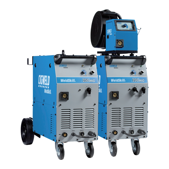
- Page 1 WELDSKILL MIG WELDING MACHINE WIREFEEDER (Optional) Operating Manual Art # A-09908_AB Version No: AE Issue Date: December 27,2013 Manual No.: 0-5182 Operating Features:...
- Page 2 YOU ARE IN GOOD COMPANY! The Brand of Choice for Contractors and Fabricators Worldwide. CIGWELD is the Market Leading Brand of Arc Welding Products for Victor Technologies. We are a mainline supplier to major welding industry sectors in the Asia Pacific and emerging global markets including;...
- Page 3 CIGWELD Pty Ltd 71 Gower Street Preston, Victoria, Australia, 3072 www.victortechnologies.com Copyright 2011, 2012, 2013 by CIGWELD All rights reserved. Reproduction of this work, in whole or in part, without written permission of the pub- lisher is prohibited. The publisher does not assume and hereby disclaims any liability to any party for any loss or damage caused by any error or omission in this Manual, whether such error results from negligence, accident, or any other cause.
-
Page 4: Table Of Contents
TABLE OF CONTENTS SECTION 1:ARC WELDING SAFETY INSTRUCTIONS AND WARNINGS......1-1 1.01 Arc Welding Hazards ..................1-1 1.02 Principal Safety Standards ................1-5 1.03 Declaration of Conformity ................1-6 SECTION 2:INTRODUCTION ................2-1 2.01 How to Use This Manual ................. 2-1 2.02 Equipment Identification ................. - Page 5 APPENDIX 3:WELDSKILL 250 MIG POWER SOURCE CIRCUIT DIAGRAM ......A-5 APPENDIX 4:WELDSKILL 350 MIG POWER SOURCE CIRCUIT DIAGRAM ......A-6 APPENDIX 5:4R WIREFEEDER CIRCUIT DIAGRAM ............ A-7 CIGWELD LIMITED WARRANTY Terms of Warranty – January 2011 Warranty Schedule – January 2011...
-
Page 7: Section 1:Arc Welding Safety Instructions And Warnings
safety instructions weldskill 250, 350 SECTION 1: ARC WELDING SAFETY INSTRUCTIONS AND WARNINGS WARNING PROTECT YOURSELF AND OTHERS FROM POSSIBLE SERIOUS INJURY OR DEATH. KEEP CHILDREN AWAY. PACEMAKER WEARERS KEEP AWAY UNTIL CONSULTING YOUR DOCTOR. DO NOT LOSE THESE INSTRUCTIONS. READ OPERATING/ INSTRUCTION MANUAL BEFORE INSTALLING, OPERATING OR SERVICING THIS EQUIPMENT. -
Page 8: Safety Instructions
weldskill 250, 350 safety instructions WARNING WARNING WELDING can cause fire or explosion. FUMES AND GASES can be hazardous to your health. Sparks and spatter fly off from the welding arc. The flying sparks and hot metal, weld spatter, hot Welding produces fumes and gases. - Page 9 safety instructions weldskill 250, 350 Recommended Protective Filters for Electric Welding Minimum Shade Number of Approximate range of Weldi Description of Process Current in Amps Filter(s) Less than or equal to 100 100 to 200 Manual Metal Arc Welding covered 200 to 300 electrodes (MMAW) 300 to 400...
- Page 10 weldskill 250, 350 safety instructions WARNING WARNING FLYING SPARKS AND HOT METAL can cause This product, when used for welding or cutting, injury. produces fumes or gases which contain chemicals know to the State of California to cause birth defects Chipping and grinding cause flying metal.
-
Page 11: Principal Safety Standards
safety instructions weldskill 250, 350 1.02 Principal Safety Standards Safety in Welding and Cutting, ANSI Standard Z49.1, from Ameri- can Welding Society, 550 N.W. LeJeune Rd., Miami, FL 33126. Safety and Health Standards, OSHA 29 CFR 1910, from Su- perintendent of Documents, U.S. Government Printing Office, Washington, D.C. -
Page 12: Declaration Of Conformity
CIGWELD has been manufacturing and merchandising an extensive equipment range with superior performance, ultra safe operation and world class quality for more than 30 years and will continue to achieve excellence. -
Page 13: Section 2:Introduction
Additional copies of this manual may be purchased by uncrating the unit. Use care to avoid damaging the contacting Cigweld at the address and phone number equipment when suing bars, hammers, etc., to uncrate for your location listed in the inside back cover of this the unit. -
Page 14: Symbol Chart
weldskill 250, 350 introduction 2.04 Symbol Chart Note that only some of these symbols will appear on your model. Wire Feed Function Single Phase Wire Feed Towards Workpiece With Three Phase Output Voltage Off. Three Phase Static Frequency Converter- Welding Gun Dangerous Voltage Transformer-Rectifier Purging Of Gas... -
Page 15: Description
1.2/1.6mm U Groove, 0.8/0.9mm V Knurled, repairs be carried out by appropriately qualified per- 1.2/1.6mm V Knurled. sons approved by CIGWELD. Advice in this regard • Contact tips: 0.6mm; 0.8mm, 0.9mm (fitted); can be obtained by contacting accredited CIGWELD 1.0mm, 1.2mm, 1.6mm Distributor. - Page 16 weldskill 250, 350 introduction WeldSkill 250 MIG Plant (Part No: W1003400) (Asia Version) • WeldSkill 250 MIG Power Source (compact) • Mig Torch MB 26 style • Work lead • Cylinder Chain • 200mm Spool Adaptor • Feed rolls: 0.6/0.8mm V Groove; 0.9/1.2mm V Groove (fitted), 1.0/1.2mm U Groove; 0.8/0.9mm V Knurled, 1.2/1.6mm V Knurled. • Contact tips: 0.6mm; 0.8mm, 0.9mm (fitted);1.0mm, 1.2mm, 1.6mm • Shielding Gas Hose Assembly • Shielding Gas Adaptor...
-
Page 17: Duty Cycle
introduction weldskill 250, 350 2.08 Duty Cycle Art# A-09909_AC WeldSkill 250 Welding Current (amps) Duty Cycle for 350 WeldSkill 350 Welding Current (amps) Art # A-08724 WeldSkill 350 Welding Current (amps) The rated duty cycle of a Welding Power Source, is a statement of the time it may be operated at its rated welding current output without exceeding the temperature limits of the insulation of the component parts. -
Page 18: Weldskill 250 Mig Power Source Specifications
weldskill 250, 350 introduction 2.09 WeldSkill 250 MIG Power Source Specifications Description WeldSkill 250 MIG Plant Part Numbers W1003400 & W1004500 Plant Dimensions H 1050mm x W 470mm x D 1020mm Power Source Mass 100kg Cooling Fan Cooled Energy Input (Refer NOTE below) This Column applies to the This Column applies to a Factory Fitted 2.5mm... -
Page 19: Weldskill 350 Mig Power Source Specifications
introduction weldskill 250, 350 2.10 WeldSkill 350 MIG Power Source Specifications Description WeldSkill 350 MIG Plant Part Numbers W1003500 & W1004600 Plant Dimensions H 1050mm x W 470mm x D 1020mm Power Source Mass 112kg Cooling Fan Cooled Input Cable Requirements 1.5mm + 3 core &... -
Page 20: Weldskill 4R Wirefeeder Specifications
weldskill 250, 350 introduction 2.11 WeldSkill 4R Wirefeeder Specifications Description WeldSkill 4R Wirefeeder Wirefeeder Plant Part Number W3000401 Wirefeeder Plant Dimensions H 490mm x W 420mm x D 670mm Wirefeeder Plant Mass 25kg Wire Feed Motor Voltage 24VDC Gas Solenoid Voltage 36VAC Minimum Wire Speed 2 m/min... -
Page 21: Section 3:Installation
installation weldskill 250, 350 SECTION 3: INSTALLATION 3.01 Environment 3.03 Ventilation These units are not designed for use in environments Since the inhalation of welding fumes can be harmful, with increased hazard of electric shock. ensure that the welding area is effectively ventilated. A. -
Page 22: Installation And Users Responsibility
weldskill 250, 350 installation 3.06 Assessment of Area The WeldSkill 350 MIG Power Source is supplied with a 15 Amp input lead and is designed for a 415 VAC Before installing welding equipment, the user shall supply voltage. make an assessment of potential electromagnetic The WeldSkill 350 MIG Power Source is suitable for problems in the surrounding area. - Page 23 installation weldskill 250, 350 B. Maintenance of Welding Equipment E. Earthing of the Workpiece The welding equipment should be routinely maintained Where the workpiece is not bonded to earth for electri- according to the manufacturer’s recommendations. All cal safety, nor connected to earth because of it’s size access and service doors and covers should be closed and position, e.g.
- Page 24 weldskill 250, 350 installation Manual 0-5182 Installation...
-
Page 25: Section 4:Operation
operation weldskill 250, 350 SECTION 4: OPERATION 4.01 Power Source Front Panel Art # 0-09919 Art # 0-09918 TORCH REMOTE REMOTE TORCH Figure 4-1 WeldSkill 250 & 350 MIG Front Panel 1. POWER ON INDICATOR/MAIN POWER CONTROL SWITCH The Power ON Indicator illuminates when the Main Power Control Switch ON/OFF knob is in the ON posi- tion and the correct mains voltage is present. - Page 26 weldskill 250, 350 operation 3. VOLTAGE CONTROL SWITCH - FINE (WELDSKILL 350 ONLY) The Fine Voltage Control switch increases the welding voltage (in smaller increments than the Coarse switch) as it is rotated in a clockwise direction. CAUTION The Coarse & Fine Voltage Control switches MUST NOT BE SWITCHED during the welding process.
-
Page 27: Power Source Internal Welding Controls
operation weldskill 250, 350 10. VOLTAGE CONTROL SWITCH (WELDSKILL 250 ONLY) The Voltage Control Switch is a 12 position that increases the welding voltage as it is rotated in a clockwise direction. CAUTION The Voltage Control switch MUST NOT BE SWITCHED during the welding process. 11. - Page 28 weldskill 250, 350 operation A. SPOT TIME SPOT (s) Art # 0-10092 When the TRIGGER MODE SELECTOR switch is switched to the SPOT position, the SPOT TIME control adjusts the duration of a single spot weld. B. TRIGGER MODE SWITCH The Trigger Mode Selector switch selects the desired welding mode.
- Page 29 operation weldskill 250, 350 D. WIRE INCH SWITCH INCH Art # 0-10094 The Wire Inch Switch is used to feed the MIG wire through the MIG torch. When the push button switch is pressed down, the electrode wire is fed through the Wirefeed system & MIG torch. No gas flows and welding voltage is not present when the Wire Inch Switch is activated.
-
Page 30: Wirefeeder Front Panel
weldskill 250, 350 operation 4.03 4R Wirefeeder Front Panel WIRESPEED Art # 0-09925_AB 1. WIRESPEED CONTROL The Wirespeed Control Knob controls the welding current via the electrode wirefeed rate, ie the speed of the wirefeed motor. 2. MIG TORCH ADAPTOR (Euro Style) The MIG torch adaptor is the connection point for the MIG welding torch. - Page 31 operation weldskill 250, 350 2. NEVER pressurize a regulator that has loose or damaged parts or is in a questionable condition. NEVER loosen a connection or attempt to remove any part of a regulator until the gas pressure has been relieved. Under pressure, gas can dangerously propel a loose part. 3.
- Page 32 weldskill 250, 350 operation 1. Slowly turn adjusting screw/knob in (clock- 5. To protect sensitive down-stream equipment wise) direction until the outlet gauge indicates a separate safety device may be necessary if the regulator is not fitted with a pressure relief the required flow rate.
-
Page 33: Section 5:Set Up For The Weldskill 250 & 350 Power Source
set up weldskill 250, 350 SECTION 5: SET UP FOR THE WELDSKILL 250 & 350 POWER SOURCE 5.01 Setup For The WeldSkill 250 & 350 MIG Power Source Power Source Connections A. Remove all packaging materials. B. Connect the work lead to the negative welding terminal (-) [positive welding terminal (+) for flux cored electrode wire]. - Page 34 weldskill 250, 350 set up Setup for MIG (GMAW) Welding with Setup for MIG (GMAW) Welding Gas Shielded Shielded MIG Wire with Gas Gasless MIG Wire 300mm Wire spool installation 200mm Wire spool installation Art# 0-09923_AD Figure 5-1 WeldSkill 250 & 350 Setup and Spool Hub Manual 0-5182 Setup...
-
Page 35: Wire Reel Brake
set up weldskill 250, 350 Inserting Wire Into The Wire Feed Mechanism Lift up the wire feeder pressure lever and pass the electrode wire through the inlet guide, between the rollers, through the centre guide, between the rollers, through the outlet guide and into the MIG torch. WARNING DO NOT WEAR GLOVES WHILE THREADING THE WIRE OR CHANGING THE WIRE SPOOL. - Page 36 weldskill 250, 350 set up trode wire manufacturer. (Power Source Torch Polarity Lead not required to be connected when using wirefeeder) B. Connect the control cable from the Wirefeeder to the control socket on the Power Source. C. Fit the gas regulator and flowmeter to the gas cylinder then connect the gas hose from the rear of the Wirefeeder to the Flowmeter outlet.
-
Page 37: Wire Reel Brake
set up weldskill 250, 350 Inserting Wire Into The Wire Feed Mechanism A. Lift up the wire feeder pressure lever and pass the electrode wire through the inlet guide, between the rollers, through the centre guide, between the rollers, through the outlet guide and into the MIG torch. WARNING DO NOT WEAR GLOVES WHILE THREADING THE WIRE OR CHANGING THE WIRE SPOOL. -
Page 38: How To Lift Weldskill 4R Wirefeeder
weldskill 250, 350 set up 5.05 How to Lift WELDSKILL 4R Wirefeeder WARNING DO NOT lift the WELDSKILL 4R Wirefeeder by the Handle using mechanical means. The WELD- SKILL 4R Wirefeeder may fall from a hook/mechanical hoist as the small bracket on the handle is not designed to secure a lifting hook/mechanical hoist in the corner of the Handle. -
Page 39: Section 6:Basic Welding Guide
Basic weldinG Guide weldskill 250, 350 SECTION 6: BASIC WELDING GUIDE 6.01 MIG (GMAW/FCAW) Basic Welding Technique Two different welding processes are covered in this section (GMAW and FCAW), with the intention of providing the very basic concepts in using the MIG mode of welding, where a welding gun is hand held, and the electrode (welding wire) is fed into a weld puddle, and the arc is shielded by an inert welding grade shielding gas or inert welding grade shielding gas mixture. -
Page 40: Basic Welding Guide
weldskill 250, 350 Basic weldinG Guide Position of MIG Torch The angle of MIG torch to the weld has an effect on the width of the weld. Push Vertical Drag/Pull Art # A-07185_AB Figure 6-3 The welding gun should be held at an angle to the weld joint. (see Secondary Adjustment Variables below) Hold the gun so that the welding seam is viewed at all times. - Page 41 Basic weldinG Guide weldskill 250, 350 10° to 20° Longitudinal Angle 10° Longitudinal Angle 30° to 60° 30° to 60° Transverse Transverse Angle Angle Direction of Travel Vertical Fillet Welds Art # A-08995 Figure 6-6 Direction of Travel 30° to 60° Transverse Angle 5°...
- Page 42 weldskill 250, 350 Basic weldinG Guide Secondary Adjustable Variables These variables cause changes in primary adjustable variables which in turn cause the desired change in the bead formation. They are: 1. Stick-out (distance between the end of the contact tube (tip) and the end of the electrode wire). Maintain at about 10mm stick-out 2.
- Page 43 Basic weldinG Guide weldskill 250, 350 Establishing the Arc and Making Weld Beads Before attempting to weld on a finished piece of work, it is recommended that practice welds be made on a sample metal of the same material as that of the finished piece. The easiest welding procedure for the beginner to experiment with MIG welding is the flat position.
- Page 44 weldskill 250, 350 Basic weldinG Guide Basic Welding Guide Manual 0-5182...
-
Page 45: Section 7:Service
The inspection and testing of the power source and associated accessories shall be carried out in accordance with Section 5 of AS 1674.2 - 2007: Safety in Welding and Allied Processes-Part 2 Electrical. This includes an insulation resistance test and an earthing test to ensure the integrity of the unit is compliant with Cigweld's original specifications. - Page 46 Output current (A) to be checked to ensure it falls within applicable Cigweld power source specifications Output Voltage (V) to be checked to ensure it falls within applicable Cigweld power source specifications Motor Speed (RPM) of wire drive motors to be checked to ensure it falls within required Cigweld power source / wire feeder specifications...
-
Page 47: Cleaning The Feed Rolls
If major complex subassemblies are faulty, then the Welding Power Source must be returned to an Accredited CIGWELD Service Provider for repair. The basic level of troubleshooting is that which can be performed without special equipment or knowledge and without removing the covers from the Wirefeeder. -
Page 48: Solving Problems Beyond The Welding Terminals - Inconsistent Wire Feed
weldskill 250, 350 service CAUTION Disengage the drive roll when testing for shielding gas flow by ear. 7.06 Solving Problems Beyond the Welding Terminals – Inconsistent Wire Feed Wire feeding problems can be reduced by checking the following points. FAULT CAUSE Wire spool brake is too tight Feed roller driven by motor in the cabinet will slip. -
Page 49: Welding Problems
service weldskill 250, 350 7.07 Welding Problems FAULT CAUSE REMEDY 1 Undercut Welding arc voltage too high. Reduce voltage by reducing the Voltage Control switch positions or turn the Wirespeed control knob anticlockwise. Incorrect torch angle Adjust angle Excessive heat input Increase the torch travel speed or reduce welding current by reducing the Voltage Control switch positions... -
Page 50: Power Source / Wirefeeder Problems
Slow the cooling rate by preheating part to be welded or cool slowly. 8 Cold weld puddle Faulty rectifier unit Have an Accredited CIGWELD Service Provider test then replace the faulty component. Loss of a phase in the Mains Check mains power supply voltage. - Page 51 Turn on. Empty Cylinder Replace cylinder. 8 Gas flow continues Gas valve has jammed open due Have an Accredited CIGWELD after the torch trigger to impurities in the gas or the gas Service Provider repair or replace switch has been line.
- Page 52 weldskill 250, 350 service Service Manual 0-5182...
-
Page 53: Appendix 1:Key Spare Parts
appendix weldskill 250, 350 APPENDIX 1: KEY SPARE PARTS Art # A-10328_AB WELDSKILL 250 MIG SPARE PARTS WELDSKILL 250 MIG SPARE PARTS Seq. Part No Description W7004501 Contactor W7004502 PCB Control W7004503 Solenoid Valve, 36VAC W7004505 Switch, On/Off, 415V W7004506 Fan Assembly, 220V W7004540 Wire Drive Assembly... - Page 54 weldskill 250, 350 appendix Art # A-10329_AB WELDSKILL 350 MIG SPARE PARTS WELDSKILL 350 MIG SPARE PARTS Seq. Part No Description W7004501 Contactor W7004502 PCB Control W7004503 Solenoid Valve, 36VAC W7004505 Switch, On/Off, 415V W7004506 Fan Assembly, 220V W7004540 Wire Drive Assembly W7004541 Local Remote Switch W7004537...
- Page 55 appendix weldskill 250, 350 Art # A-10330_AB WELDSKILL 4R WIREFEEDER SPARE PARTS WELDSKILL 4R WIREFEEDER SPARE PARTS Seq. Part No Description W7004540 Wire Drive Assembly W7004539 Solenoid Valve, 36VAC W7004543 Euro Adaptor, (includes rear stem assembly) W7004544 Wire Reel Hub Manual 0-5182 Appendix...
-
Page 56: Appendix 2:Volt/Amp Curves
weldskill 250, 350 appendix APPENDIX 2: VOLT/AMP CURVES WeldSkill 250 VA Curve WeldSkill 250 VA Curve 50.0 45.0 40.0 35.0 30.0 25.0 20.0 15.0 10.0 Amps Art # 0-08731 WeldSkill 350 VA Curve Weldskill 350 VA Curve 45.0 40.0 35.0 30.0 25.0 20.0... -
Page 57: Appendix 3:Weldskill 250 Mig Power Source Circuit Diagram
appendix weldskill 250, 350 APPENDIX 3: WELDSKILL 250 MIG POWER SOURCE CIRCUIT DIAGRAM Manual 0-5182 Appendix... -
Page 58: Appendix 4:Weldskill 350 Mig Power Source Circuit Diagram
weldskill 250, 350 appendix APPENDIX 4: WELDSKILL 350 MIG POWER SOURCE CIRCUIT DIAGRAM Appendix Manual 0-5182... -
Page 59: Appendix 5:4R Wirefeeder Circuit Diagram
appendix weldskill 250, 350 APPENDIX 5: 4R WIREFEEDER CIRCUIT DIAGRAM Art # A-09928_AB Manual 0-5182 Appendix... - Page 60 weldskill 250, 350 appendix Appendix Manual 0-5182...
-
Page 61: Cigweld Limited Warranty
WELD whether arising out of contract, negligence, strict tort, or under any warranty, or otherwise, shall not, except as expressly provided herein, exceed the price of the goods upon which such liability is based. No employee, agent, or representative of CIGWELD is authorized to change this warranty in any way or grant any other warranty. - Page 62 CIGWELD. 4. CIGWELD declares that, to the extent permitted by law, it hereby limits its liability in respect of the supply of goods which are not of a kind ordinarily acquired for personal, domestic or household use or consumption to any one or more of the following (the choice of which shall be at the option of CIGWELD).
- Page 63 Accredited Distributor of the equipment. Notwithstanding the foregoing, in no event shall the warranty period extend more than the time stated plus one year from the date CIGWELD delivered the product to the Accredited Distributor. Unless otherwise stated the warranty period includes parts and labour. CIGWELD reserves the right to request documented evidence of date of purchase.
-
Page 65: Global Customer Service Contact Information
GLOBAL CUSTOMER SERVICE CONTACT INFORMATION Cigweld, Australia Victor Technologies, China 71 Gower Street No.100 Lao Hongjing Rd, Preston, Victoria Minhang District Australia, 3072 Shanghai 200235 Telephone: 61-3-9474-7400 China Fax: 61-3-9474-7391 Telephone: 86-21-64072626 Email: enquiries@cigweld.com.au Fax: 86-21-64483032 Victor Technologies Asia Sdn Bhd... - Page 66 Asia Pacific Regional Headquarters 71 Gower Street Preston, Victoria, Australia, 3072 Telephone: +61 3 9474 7400 FAX: +61 3 9474 7391 Email: enquiries@cigweld.com.au www.cigweld.com.au...
Need help?
Do you have a question about the 250 WELDSKILL and is the answer not in the manual?
Questions and answers