
Related Manuals for CIGWELD TRANSTIG 200


Summary of Contents for CIGWELD TRANSTIG 200
- Page 1 200 ac/dc ® transtig inverter arc welder service Manual Revision No: AB Issue Date: January 10, 2014 Manual No.: 0-5001 Operating Features: INVERTER...
- Page 2 WE APPRECIATE YOUR BUSINESS! Congratulations on your new CIGWELD product. We are proud to have you as our customer and will strive to provide you with the best service and reliability in the industry. This product is backed by our extensive warranty and world-wide service network. To locate your nearest distributor or service agency please call +61-3-9474-7400, or visit us on the web at www.cigweld.com.
- Page 3 While the information contained in this Manual represents the Manufacturer's best judgement, the Manufacturer assumes no liability for its use. Transtig 200 AC/DC Inverter Arc Welder Operating Manual Number 0-5001 for: Part Number 700719 Published by: Victor Technologies International Inc.
-
Page 4: Table Of Contents
OPERATOR CONTROLS ................4-1 4.01 Transtig 200 AC/DC Controls ................4-1 4.02 Weld Process Selection for Transtig 200 AC/DC ..........4-3 4.03 Weld Parameter Descriptions for Transtig 200 AC/DC ........4-4 4.04 Weld Parameters for Transtig 200 AC/DC ............4-6 4.05... - Page 5 TABLE OF CONTENTS TABLE OF CONTENTS (continued) SECTION 7: BASIC TIG WELDING GUIDE ................ 7-1 7.01 Explanation of “Fluttery Arc” when AC TIG Welding on Aluminum ....7-1 7.02 Electrode Polarity .................... 7-2 7.03 Tungsten Electrode Current Ranges ..............7-2 7.04 Tungsten Electrode Types ................
- Page 6 TABLE OF CONTENTS 12.03 Verification and Remedy to Failures without Indication Codes ...... 12-6 12.3.1 "Cooling Fan (FAN1) Failure" (Fan is not rotating.) ......12-6 12.3.2 "Gas Valve Failure" (No Gas flow through unit) ........12-7 12.3.3 "No Weld Output" ................12-7 12.3.4 "Operating Panel Failure"...
- Page 7 APPENDIX 2: CONNECTION WIRING GUIDE ............A-5 APPENDIX 3: DIODE TESTING BASICS ..............A-7 APPENDIX 4: TRANSTIG 200 AC/DC ACCESSORIES ........... A-8 APPENDIX 5: TRANSTIG 200 AC/DC INTERCONNECTION DIAGRAM ........ A-9 CIGWELD LIMITED WARRANTY TERMS OF WARRANTY – JANUARY 2008 WARRANTY SCHEDULE –...
- Page 8 TABLE OF CONTENTS TABLE OF CONTENTS (continued) THIS PAGE LEFT INTENTIONALLY BLANK...
-
Page 9: Arc Welding Safety Instructions And Warnings
SERVICE MANUAL TRANSTIG 200 AC/DC SECTION 1: ARC WELDING SAFETY INSTRUCTIONS AND WARNINGS WARNING PROTECT YOURSELF AND OTHERS FROM POSSIBLE SERIOUS INJURY OR DEATH. KEEP CHILDREN AWAY. PACEMAKER WEARERS KEEP AWAY UNTIL CONSULTING YOUR DOCTOR. DO NOT LOSE THESE INSTRUCTIONS. READ OPERATING/INSTRUCTION MANUAL BEFORE INSTALLING, OPERATING OR SERVICING THIS EQUIPMENT. - Page 10 TRANSTIG 200 AC/DC SERVICE MANUAL WARNING WARNING FUMES AND GASES can be hazardous to your WELDING can cause fire or explosion. health. Sparks and spatter fly off from the welding arc. The Welding produces fumes and gases. Breathing flying sparks and hot metal, weld spatter, hot work- these fumes and gases can be hazardous to your piece, and hot equipment can cause fires and burns.
- Page 11 SERVICE MANUAL TRANSTIG 200 AC/DC WARNING WARNING FLYING SPARKS AND HOT METAL can cause ENGINE FUEL can cause fire or explosion. injury. Engine fuel is highly flammable. Chipping and grinding cause flying metal. As welds cool, they can throw off slag.
-
Page 12: Principal Safety Standards
TRANSTIG 200 AC/DC SERVICE MANUAL 1.02 PRINCIPAL SAFETY STANDARDS Safety in Welding and Cutting, ANSI Standard Z49.1, from American Welding Society, 550 N.W. LeJeune Rd., Miami, FL WARNING 33126. Safety and Health Standards, OSHA 29 CFR 1910, from STEAM AND PRESSURIZED HOT COOLANT can Superintendent of Documents, U.S. -
Page 13: Declaration Of Conformity
Rigorous testing is incorporated into the manufacturing process to ensure the manufactured product meets or exceeds all design specifications. CIGWELD has been manufacturing and merchandising an extensive equipment range with superior performance, ultra safe operation and world class quality for more than 30 years and will continue to achieve excellence. - Page 14 TRANSTIG 200 AC/DC SERVICE MANUAL Classification: The equipment described in this manual is Class A and intended for industrial use. Warning This Class A equipment is not intended for use in residential locations where the electrical power is provided by the public low-voltage supply system.
-
Page 15: Introduction
CIGWELD at the address and phone CAUTION number for your location listed in the inside back cover of this manual. Include the Transtig 200 AC/DC Service Manual number and equipment The products applicable to this Service Manual are manufactured in various configurations for identification numbers. -
Page 16: Symbol Chart
TRANSTIG 200 AC/DC SERVICE MANUAL 2.04 Symbol Chart Note that only some of these symbols will appear on your model . Wire Feed Function Single Phase Wire Feed Towards Workpiece With Three Phase Output Voltage Off. Three Phase Static Frequency Converter-... -
Page 17: Description
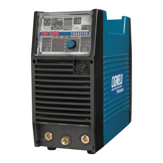
SERVICE MANUAL TRANSTIG 200 AC/DC 2.05 Description Art # A-07443 The Transtig 200 AC/DC is a self contained single- phase AC/DC arc welding power source with Constant Current (CC) output characteristics. This unit is equipped with a Digital Volt/Amperage Meter,... -
Page 18: Functional Block Diagrams
Mode select Switches Panel Circuit Board Art # A-07267 Figure 2-2: Transtig 200 AC/DC Functional Block Diagram 2.07 Transporting Methods • Lift unit with handle on top of case. • Use handcart or similar device of adequate This unit is equipped with a handle for carrying capacity. -
Page 19: Parameter Specifications
SERVICE MANUAL TRANSTIG 200 AC/DC 2.08 Parameter Specifications Parameter Transtig 200 AC/DC Power Source Part Number 700719 Cooling Fan Cooled Welder Type Inverter Power Source Welding Power Source Mass 19kg Dimensions H 360mm x W 180mm x L 420mm Manufactured to Australian Standard AS 60974.1-2006... - Page 20 TRANSTIG 200 AC/DC SERVICE MANUAL NOTES Manual No. 0-5001...
-
Page 21: Installation
TRANSTIG 200 AC/DC SECTION 3: INSTALLATION 3.03 Electrical Input Connections 3.01 Environment The Transtig 200 AC/DC is designed for use in hazardous environments. Examples of environments WARNING with increased hazardous conditions are: ELECTRIC SHOCK can kill; SIGNIFICANT DC a. In locations in which freedom of movement VOLTAGE is present after removal of input power. -
Page 22: Mains Supply Voltage Requirements
• Correctly earthed (electrically) in accordance with local regulations. • Connected to the correct size 240V Mains Current Circuit as per the Specifications WARNING CIGWELD advises that this equipment be electrically connected by a qualified electrical trades-person. The following 240V Mains Current Circuit recommendations are required to obtain the maximum welding current and duty cycle from this welding equipment: NOTE This product has been fitted with a 15 amp input supply plug as standard. -
Page 23: High Frequency Introduction
SERVICE MANUAL TRANSTIG 200 AC/DC 3.05 High Frequency Introduction 3.06 High Frequency Interference T h e i m p o r t a n c e o f c o r r e c t i n s t a l l a t i o n o f... -
Page 24: Duty Cycle
TRANSTIG 200 AC/DC SERVICE MANUAL 3.07 Duty Cycle CAUTION The duty cycle of a welding power source is the percentage of a ten (10) minute period that it can Continually exceeding the duty cycle ratings can be operated at a given output without causing cause damage to the welding power source and will void the manufacturer's warranty. -
Page 25: Operator Controls
TRANSTIG 200 AC/DC SECTION 4: OPERATOR CONTROLS 4.01 Transtig 200 AC/DC Controls Art # A-08341_AC Figure 4-1: Transtig 200 AC/DC Power Source 1. Control Knob: This control sets the selected Socket Pin Function weld parameter, rotating it clockwise increases Earth (Ground) - Page 26 TRANSTIG 200 AC/DC SERVICE MANUAL 3. Positive Terminal: Welding current flows from the Power Source via heavy duty Dinse type WARNING terminal. It is essential, however, that the male plug is inserted and turned securely to achieve a When the welder is connected to the Primary supply sound electrical connection.
-
Page 27: Weld Process Selection For Transtig 200 Ac/Dc
SPOT Pulse operation in TIG Modes PULSE ON/OFF Selects AC or DC weld current Selects mode of operation: Panel or Remote Operation PANEL/ REMOTE Table 4-2: Weld Process selection versus Weld Mode for Transtig 200 AC/DC Manual No. 0-5001... -
Page 28: Weld Parameter Descriptions For Transtig 200 Ac/Dc
This parameter operates in TIG modes only and is used to set the time for UP SLOPE the weld current to ramp up, after the torch trigger switch has been pressed then released, from INITIAL CUR to PEAK or BASE current Table 4-3: Transtig 200 AC/DC Front Panel Parameter Description Manual No. 0-5001... - Page 29 The SAVE/LOAD buttons are used to save and retrieve a total number of 5 programs into the 200AC/DC memory. Note: Press button for three seconds to store settings. Table 4-3: Transtig 200 AC/DC Front Panel Parameter Description (cont.) Manual No. 0-5001...
-
Page 30: Weld Parameters For Transtig 200 Ac/Dc
DOWN SLOPE 5 to 185A CRATER CUR. 0.0 to 60 sec 10 sec 0.1 sec POST-FLOW Table 4-4: Weld Parameters for Transtig 200 AC/DC PULSE FREQ. Range Incremental Unit 0.5 to 20Hz 0.1Hz 20 to 100Hz 100 to 500Hz Table 4-5: PULSE FREQ. Range and Incremental Units... -
Page 31: Power Source Features
SERVICE MANUAL TRANSTIG 200 AC/DC 4.05 Power Source Features Feature Description • Almost all welding parameters are adjustable New Digital Control • Touch switches eliminate mechanical damage Touch Panel Switches • Protects front panel controls Front Control Cover • Displays selected weld parameter value Digital Meter • Displays weld current when welding... - Page 32 TRANSTIG 200 AC/DC SERVICE MANUAL Feature Description • A total number of 5 programs can be saved into the 200 Save/Load Function AC/DC memory. SAVE the Current Weld Parameters into Memory • Press and HOLD the SAVE button for three seconds.
-
Page 33: Set-Up For Smaw (Stick) And Gtaw (Tig)
Primary power supply is switched off. Art # A-07843 CAUTION Figure 5-1: Transtig 200 AC/DC Set-up Remove any packaging material prior to use. Do not block the air vents at the front or rear or sides of the Welding Power Source. - Page 34 TRANSTIG 200 AC/DC SERVICE MANUAL NOTES Manual No. 0-5001...
-
Page 35: Sequence Of Operation
Symbol descriptions. PRESS AND HOLD Art # A-07272_AC Figure 6-1: Transtig 200 AC/DC Front Panel 1. Pulse Function: Pressing this button enables the TIG current pulse functions. 2. Remote Current Function: Pressing this buttons enables remote current functions. -
Page 36: Stick Welding
TRANSTIG 200 AC/DC SERVICE MANUAL 6.01 Stick Welding 6.02 AC or DC HF TIG Welding · Connect work lead to negative terminal · Connect work lead to positive terminal · Connect electrode lead to positive terminal · Connect TIG torch to gas terminal ·... -
Page 37: Slope Mode Sequence
SERVICE MANUAL TRANSTIG 200 AC/DC 6.03 Slope Mode Sequence Art # A-04989 Switch Switch Switch Switch Closed Closed Open Open Weld Current Down Slope Slope Initial Final Current Current Preflow Postflow Figure 6-2: Slope Mode Sequence Note S l o p e f u n c t i o n o p e r a t e s w i t h a R e m o t e ON/OFF device only 1. -
Page 38: Pulse Controls
TRANSTIG 200 AC/DC SERVICE MANUAL 6.05 Pulse Controls (Pulse Width) (Pulse Frequency) Art # A-04990 (Peak Current) (Base) Background Current Figure 6-3: Pulse Controls The Pulse controls are used primarily to control heat input. Pulse offers a number of advantages as follows: 1) Control puddle –... -
Page 39: Basic Tig Welding Guide
SERVICE MANUAL TRANSTIG 200 AC/DC SECTION 7: BASIC TIG WELDING GUIDE 7.01 Explanation of “Fluttery Arc” This idea is supported by the observation that once fluttering starts it can be made to stop by working when AC TIG Welding on... -
Page 40: Electrode Polarity
TRANSTIG 200 AC/DC SERVICE MANUAL 7.02 Electrode Polarity Connect the TIG torch to the - / TORCH terminal and the work lead to the + / WORK terminal for direct current straight polarity. Direct current straight polarity is the most widely used polarity for DC TIG welding. -
Page 41: Guide For Selecting Filler Wire Diameter
SERVICE MANUAL TRANSTIG 200 AC/DC 7.05 Guide for Selecting Filler Wire Diameter NOTE The filler wire diameter specified in Table 7-4 is a guide only, other diameter wires may be used according to the welding application Filler Wire Diameter AC Current Range... -
Page 42: Welding Parameters For Aluminum
TRANSTIG 200 AC/DC SERVICE MANUAL 7.08 Welding Parameters for Aluminum Base Metal AC Current for Tungsten Filler Rod Argon Gas Joint Type Thickness Aluminum Electrode Diameter Flow Rate Diameter (if required) Liters/min 0.040” 30-45 0.040” 1/16” Butt/Corner 1.0mm 35-50 1.0mm 1.6mm... -
Page 43: Basic Arc Welding Guide
SERVICE MANUAL TRANSTIG 200 AC/DC SECTION 8: BASIC ARC WELDING GUIDE 8.01 Electrode Polarity Types of Electrodes Arc Welding electrodes are classified into a number Stick electrodes are generally connected to the ‘+’ of groups depending on their applications. There terminal and the work lead to the ‘-’... - Page 44 TRANSTIG 200 AC/DC SERVICE MANUAL Metals being Electrode Comments joined Mild Steel 6013 Ideal electrodes for all general purpose work. Features include outstanding operator appeal, easy arc starting and low spatter. Mild Steel 7014 All positional electrode for use on...
-
Page 45: Routine Maintenance
Turn Power Switch to OFF before proceeding. Internal cleaning of the unit should be done every 6 months by an authorized CIGWELD Service Center to remove any accumulated dirt and dust. This may need to be done more frequently under exceptionally dirty conditions. - Page 46 TRANSTIG 200 AC/DC SERVICE MANUAL Warning! Disconnect input power before maintaining. Maintain more often if used under severe conditions Each Use Visual check of torch Visual check of Consumable parts regulator and pressure Weekly Visually inspect the torch Visually inspect the body and consumables cables and leads.
-
Page 47: Basic Troubleshooting
WARNING There are extremely dangerous voltages and power levels present inside this product. Do not attempt to open or repair unless you are an accredited CIGWELD Service Provider and you have had training in power measurements and troubleshooting techniques. If major complex subassemblies are faulty, then the Welding Power Source must be returned to an accredited CIGWELD Service Provider for repair. - Page 48 TRANSTIG 200 AC/DC SERVICE MANUAL Description Possible Cause Remedy Electrode melts when Electrode is connected to the Connect the electrode to the arc is struck. ‘+’ terminal. ‘ - ’ terminal. WAVE BALANCE is greater Reduced WAVE BALANCE than 50%.
- Page 49 SERVICE MANUAL TRANSTIG 200 AC/DC Description Possible Cause Remedy 11 Welding arc cannot A Work clamp is not connected to A Connect the work clamp to the be established. the work piece or the work/torch work piece or connect the work/...
-
Page 50: Stick Welding Problems
TRANSTIG 200 AC/DC SERVICE MANUAL 10.02 Stick Welding Problems Description Possible Cause Remedy 1 Gas pockets or Electrodes are damp. Dry electrodes before use. voids in weld metal Welding current is too high. Reduce welding current. (Porosity). Surface impurities such as oil, Clean joint before welding. - Page 51 SERVICE MANUAL TRANSTIG 200 AC/DC Description Possible Cause Remedy 4 Portions of the weld Small electrodes used on heavy Use larger electrodes and run do not fuse to the cold plate. pre-heat the plate. surface of the metal Welding current is too low.
- Page 52 TRANSTIG 200 AC/DC SERVICE MANUAL Description Possible Cause Remedy 5 Non-metallic parti- A Non-metallic particles may A If bad undercut is present, clean cles are trapped in be trapped in undercut from slag out and cover with a run from the weld metal (slag previous run.
-
Page 53: Power Source Problems
The Welding Power Source Switch ON the Welding switch is switched OFF. Power Source. C Loose connections internally. C Have an accredited CIGWELD Service Provider repair the connection. 2 Maximum output Defective control circuit. Have an accredited CIGWELD welding current can... - Page 54 Switch machine OFF then ON to reset solenoid valve sequence. B Gas valve is faulty. B Have an accredited CIGWELD Service Agent Provider or replace the gas valve. C Gas valve jammed open. C Have an accredited CIGWELD Service Provider repair or replace the gas valve.
-
Page 55: Power Source Error Codes
SERVICE MANUAL TRANSTIG 200 AC/DC 10.04 Power Source Error Codes Description Possible Cause Remedy Remarks 1 E01 error code The Welding Power Let Power Source cool Weld current displayed. Source's duty cycle has down then keep within ceases. Temperature been exceeded. -
Page 56: Power Source Error Codes (Con't)
TRANSTIG 200 AC/DC SERVICE MANUAL 10.04 Power Source Error Codes (con't) Description Possible Cause Remedy Remarks E14 error code Mains supply voltage Have an Accredited Weld current displayed. Under is less than the Cigweld Service available. mains supply (input) nominal operating... -
Page 57: Voltage Reduction Device (Vrd)
A transportable power source is any equipment that is not permanently connected and fixed in the position in which it is operated. In addition to the above tests and specifically in relation to the VRD fitted to this machine, the following periodic tests should also be conducted by an accredited Cigweld service Provider. Description Required Parameters VRD Open Circuit Voltage Less than 20V;... - Page 58 TRANSTIG 200 AC/DC SERVICE MANUAL NOTES Manual No. 0-5001 11-2...
-
Page 59: Advanced Trouble Shooting
SERVICE MANUAL TRANSTIG 200 AC/DC SECTION 12: ADVANCED TROUBLE SHOOTING 12.00 Introduction 12.01 System-Level Fault Isolation If you are here, all of the troubleshooting sugges- If none of the suggestions provided in Section 5 tions in Section 5 Basic Troubleshooting have either... - Page 60 TRANSTIG 200 AC/DC SERVICE MANUAL Figure 12-2: Remove screws 3) Loosen the screws on the front panel and the rear panel by turning them approximately two turns CCW. Figure 12-4: Loosen front and rear panels NOTE 5) Remove the Side Panel.
-
Page 61: Verification And Remedy To The Indicated Error Codes
SERVICE MANUAL TRANSTIG 200 AC/DC 12.2.1 E01 "Over-Temperature at the primary 6) Remove protection cover sheet by removing the plastic tabs. side" Cause Occurs when an over-temperature con- dition of the primary IGBT is detected. Verification/Remedy a. Unit may be in thermal shutdown mode. -
Page 62: E02 "Over-Temperature At The Secondary Side
TRANSTIG 200 AC/DC SERVICE MANUAL 12.2.2 E02 "Over-Temperature at the 12.2.3 E03 "Primary Over-Current Failure" secondary side" Cause Cause Occurs when excessive current is de- tected flowing into the primary side of Occurs when an over-temperature con- the main transformer. -
Page 63: E11 "Main Supply Over Voltage
SERVICE MANUAL TRANSTIG 200 AC/DC Refer to 2.9 for the recommended duty cycle. • Re-install the harness with a secure connec- tion. b. Replace PCB6 (WK-5549) and PCB13 (WK- • Contact the manufacturer if you find any bro- 5569). ken connectors or a damaged wiring harness. • Refer to section 13.3.5 for the replacement of c. -
Page 64: E85 "Pre-Charge Abnormality
TRANSTIG 200 AC/DC SERVICE MANUAL • Check whether there are any abnormalities on • Refer to section 13.3.5. the appearance of PCB4. 12.2.12 E99 "Initial Power Receiving" • Replace PCB4. Refer to section 13.3.4. Cause 12.2.10 E85 "Pre-charge abnormality" Occurs when the initial AC power re- Cause ceived signal has not reached the CPU. -
Page 65: Gas Valve Failure" (No Gas Flow Through Unit)
SERVICE MANUAL TRANSTIG 200 AC/DC • Replace wiring harnesses if you find any bro- • Replace PCB3, when abnormal. ken connectors or damaged wiring harnesses. • Refer to section 13.3.3. • Replace the fan if there are any broken, e. Replace the PCB6 (WK-5549). cracked or missing fan blades. • Refer to section 13.3.5. • Refer to section 13.3.24. -
Page 66: Operating Panel Failure
TRANSTIG 200 AC/DC SERVICE MANUAL c. Verify the no-load voltage (OCV). (Applies to b. Verify the connection between PCB5 (WK- 5551) STICK, High Frequency TIG (HF TIG) mode.) and PCB6 (WK-5549). c. Replace PCB5 (WK-5551) and PCB6 (WK- • Refer to the section 12.5.9 "Verification of No- 5549). -
Page 67: Fault Isolation Tests
SERVICE MANUAL TRANSTIG 200 AC/DC c. Verify the connection between the terminals be- tween AC1-AC2 (TB1-TB2). WARNING • Verify the connection between AC1-AC2, con- firm that the quick-disconnect terminals are Dangerous voltage and power levels are present inside this unit. Be sure the operator is equipped with inserted onto the terminals of HF UNIT1 cor- proper gloves, clothing and eye and ear protection. -
Page 68: Verification Of Power Supply Voltage
TRANSTIG 200 AC/DC SERVICE MANUAL ing may cause the input voltage to decrease to a PCB1. See Figure 12-9. The measured voltage value below the operating range of the unit. should be approximately 1.4 times larger than input voltage measured in #1 above. Replace 3. -
Page 69: Verification Of The Cooling Fan, Fan1, Drive Circuitry
SERVICE MANUAL TRANSTIG 200 AC/DC 12.5.3 Verification of the Cooling Fan, FAN1, Drive Circuitry CAUTION Before performing any portion of the procedure below, make certain the unit is placed in the initial set up condition as described in section 12. 4.1 "Preparation". -
Page 70: Verification Of The Gas Valve, Sol1, Drive Circuitry
TRANSTIG 200 AC/DC SERVICE MANUAL 12.5.5 Verification of the primary Diode (D1) • During low output and standby, fan rotation becomes slower. Therefore, exact voltage measurement becomes impossible. CAUTION • When verifying the voltage, confirm that the AC input voltage remains within the operating... -
Page 71: Verification Of The Secondary Diode (D2, D4, D5)
SERVICE MANUAL TRANSTIG 200 AC/DC 12.5.6 Verification of the secondary Diode 12.5.7 Verification of the primary IGBT (Q1- (D2, D4, D5) Q12) CAUTION Before performing any portion of the procedure below, make certain the unit is placed in the initial Before performing any portion of the procedure set up condition as described in section 12. -
Page 72: Verification Of The Secondary Igbt (Q13)
TRANSTIG 200 AC/DC SERVICE MANUAL 12.5.8 Verification of the secondary IGBT 12.5.9 Verification of No-load Voltage (OCV) (Q13) CAUTION CAUTION Before performing any portion of the procedure below, make certain the unit is placed in the initial Before performing any portion of the procedure set up condition as described in section 12. - Page 73 SERVICE MANUAL TRANSTIG 200 AC/DC Figure 12-18: Removal and installation from the HF UNIT1 (To disable the operation of the HF unit.) 4. Press the Welding mode selection button to se- lect HF TIG welding mode. 5. While depressing the Torch switch, verify the OCV using a DC voltmeter.
- Page 74 TRANSTIG 200 AC/DC SERVICE MANUAL THIS PAGE LEFT INTENTIONALLY BLANK Manual No. 0-5001 12-16...
-
Page 75: Maintenance
SERVICE MANUAL TRANSTIG 200 AC/DC 13 MAINTENANCE Maintenance List MAINTENANCE DWG No. Parts name Reference page Note 13-9 PCB3 Print Circuit Board (WK-5548) 13-13 PCB10 Print Circuit Board (WK-5527) 13-13 PCB11 Print Circuit Board (WK-5528) 13-15 PCB12 Print Circuit Board (WK-5615) - Page 76 TRANSTIG 200 AC/DC SERVICE MANUAL MAINTENANCE DWG No. Parts name Reference page Part No. 13-6 W7001402 PCB1 Print Circuit Board (WK-5477) 13-7 W7001601 PCB2 Print Circuit Board (WK-5596) 13-10 10-6635 PCB4 Print Circuit Board (WK-4819) 13-10 W7001417 PCB5 Print Circuit Board (WK-5551)
- Page 77 SERVICE MANUAL TRANSTIG 200 AC/DC MAINTENANCE DWG No. Parts name Reference page Part No. 13-24 W7001384 Coupling Coil 13-15 W7001304 Current Trans 13-32 10-6628 Primary Diode 13-33 10-6629 Secondary Diode 13-33 10-6629 Secondary Diode 13-33 10-6629 Secondary Diode 13-31 W7001502...
- Page 78 TRANSTIG 200 AC/DC SERVICE MANUAL MAINTENANCE DWG No. Parts name Reference page Part No. 13-29 W7001595 CON1 Remote Connector 13-27 W7001307 FAN1 Cooling Fan 13-34 10-6643 Q13 (PCB15) Secondary IGBT (WK-3367) 13-22 10-5137 Discharge Resistor 13-23 W7001452 Current Limiting Resistor...
-
Page 79: Service Tools
SERVICE MANUAL TRANSTIG 200 AC/DC MAINTENANCE Service Tools 2.1 Tools and parts The tools and parts to be used for maintenance are shown by icons. Long Nose Philips Head Silicon Spanner C-Ring Pliers Snap Band Screwdriver Pliers Compound (5.5, 8, 10, 17mm) 2.2 Notes of disassembly and assembly... -
Page 80: Replacement Procedure
TRANSTIG 200 AC/DC SERVICE MANUAL MAINTENANCE Replacement Procedure 3.1 PCB1 (WK-5477) 1) Remove the Side Panel. [Reference page: 11-1] 2) Remove the PCB18 (WK-5861). [Reference page: 12-21] 3) Remove PCB2 (WK-5596). [Reference page: 12-7] 4) Remove the PCB8 (WK-5479). [Reference page: 12-11] 5) Remove the PCB9 (WK-5479). -
Page 81: Pcb2 (Wk-5596)
SERVICE MANUAL TRANSTIG 200 AC/DC MAINTENANCE 3.2 PCB2 (WK-5596) 1) Remove the Side Panel. [Reference page: 11-1] 2) Remove the PCB18 (WK-5861). [Reference page: 12-11] 3) Disconnect the 13 connectors. CN17 CN19 CN21 CN11 4) Remove the four screws and two ground terminals. - Page 82 TRANSTIG 200 AC/DC SERVICE MANUAL MAINTENANCE Remove the Insulated Sheet. CN15 CN14 6) Remove the three screws and seven terminals. Remove the PCB2 (WK-5596). 7) Disconnect the three connectors and two terminal from the PCB2 (WK-5596). Manual No. 0-5001 13-8...
-
Page 83: Pcb3 (Wk-5548), Pcb5 (Wk-5551)
SERVICE MANUAL TRANSTIG 200 AC/DC MAINTENANCE 3.3 PCB3 (WK-5548), PCB5 (WK-5551) 1) Remove the Side Panel. [Reference page: 11-1] 2) Remove PCB4 (WK-4819). [Reference page: 12-10] 3) Remove PCB6 (WK-5549). [Reference page: 12-10] 4) Remove PCB7 (WK-5550). [Reference page: 12-11] 5) Disconnect the 11 connectors. -
Page 84: Pcb4 (Wk-4819)
TRANSTIG 200 AC/DC SERVICE MANUAL MAINTENANCE 8) Disconnect the two connectors from the PCB3 (WK-5548). CN18 CN33 3.4 PCB4 (WK-4819) 1) Remove the Side Panel. [Reference page: 11-1] 2) Remove the two screws and three connectors and remove the PCB4 (WK-4819). -
Page 85: Pcb7 (Wk-5550)
SERVICE MANUAL TRANSTIG 200 AC/DC MAINTENANCE 3) Remove the three screws and five connectors. Remove the PCB6 (WK-5549). CN27 CN18 CN32 CN30 CN31 3.6 PCB7 (WK-5550) 1) Remove the Side Panel. [Reference page: 11-1] 2) Remove the PCB6 (WK-5549). [Reference page: 12-10] 3) Remove the two screws and three connectors. -
Page 86: Pcb9 (Wk-5479) (Igbt (Q7~Q12))
TRANSTIG 200 AC/DC SERVICE MANUAL MAINTENANCE 3) Remove the two connectors and three screws. Remove the PCB8 (WK-5479). Remember to install silicone rubber sheets when reinstalling the PCB8 (WK-5479). 3.8 PCB9 (WK-5479) (IGBT (Q7~Q12)) 1) Remove the Side Panel. [Reference page: 11-1] 2) Remove the four screws and two IGBT Chassis. -
Page 87: Pcb10 (Wk-5527)
SERVICE MANUAL TRANSTIG 200 AC/DC MAINTENANCE 3.9 PCB10 (WK-5527) 1) Remove the Side Panel. [Reference page: 11-1] 2) Remove the PCB11 (WK-5528). [Reference page: 12-13] 3) Remove the three latches of Front Control Cover and then the PCB10 (WK-5527). When reinstalling the PCB10 (WK-5527), engage two latches of Front Control Cover first. - Page 88 TRANSTIG 200 AC/DC SERVICE MANUAL MAINTENANCE 3) Remove the Knob Cap. Holding the Knob down, loosen the screw and remove the Knob. 4) Disconnect the one connector from the PCB10 (WK-5527). Remove the four screws. Pull out the Opera- tion Panel and bring it down.
-
Page 89: Pcb12 (Wk-5615), Transformer (T1), Current Trans (Ct2)
SERVICE MANUAL TRANSTIG 200 AC/DC MAINTENANCE 3.11 PCB12 (WK-5615), Transformer (T1), Current Trans (CT2) 1) Remove the Side Panel. [Reference page: 11-1] 2) Remove PCB13 (WK-5569). [Reference page: 12-18] 3) Disconnect the one connector and cut the one snap band. - Page 90 TRANSTIG 200 AC/DC SERVICE MANUAL MAINTENANCE 6) Remove the 16 screws. 7) Remove the PCB12 and T1 unit. 8) Cut the one snap band and remove the Current Trans (CT2). Manual No. 0-5001 13-16...
- Page 91 SERVICE MANUAL TRANSTIG 200 AC/DC MAINTENANCE 9) Remove the Dust Cover Sheet. Extend the electrode and remove the T-D Bus Bar1, T-D Bus Bar2 and T Center Bus Bar. 10) Remove the two PCB supporters and cushion. Remove the four screws and remove the Main Trans (T1).
-
Page 92: Pcb13 (Wk-5569)
TRANSTIG 200 AC/DC SERVICE MANUAL MAINTENANCE 3.12 PCB13 (WK-5569) 1) Remove the Side Panel. [Reference page: 11-1] 2) Remove the Nylon Hose. Remove the four screws. Remove the two terminals and open the Rear Panel. 3) Disconnect the six connectors and remove the two screws and two terminals. -
Page 93: Pcb16 (Wk-5499)
SERVICE MANUAL TRANSTIG 200 AC/DC MAINTENANCE 3.13 PCB16 (WK-5499) 1) Remove the Side Panel. [Reference page: 11-1] 2) Remove the Nylon Hose. 3) Disconnect the two connectors. Remove the three PCB supporters and remove the PCB16 (WK-5499). 3.14 PCB14 (WK-5570) 1) Remove the Side Panel. -
Page 94: Pcb17 (Wk-4917)
TRANSTIG 200 AC/DC SERVICE MANUAL MAINTENANCE 4) Remove the three PCB supporters from the PCB14 (WK-5570). 3.15 PCB17 (WK-4917) 1) Remove the Side Panel. [Reference page: 11-1] 2) Remove the four screws and four terminals. 3) Remove the four screws and then open the Rear Board. -
Page 95: Pcb18 (Wk-5861)
SERVICE MANUAL TRANSTIG 200 AC/DC MAINTENANCE 4) Disconnect the one connector. Remove the two screws and one ground terminal and remove the PCB17 unit. 5) Remove the two screws and remove the S1 Bus Bar from the PCB17 (WK-4917). 3.16 PCB18 (WK-5861) 1) Remove the Side Panel. -
Page 96: Discharge Resistor (R3)
TRANSTIG 200 AC/DC SERVICE MANUAL MAINTENANCE 3.17 Discharge Resistor (R3) 1) Remove the Side Panel. [Reference page: 11-1] 2) Remove the Nylon Hose. Remove the two bolts, two toothed washers, one washer, and one terminal. 3) Remove the four screws and open the Front Panel. -
Page 97: Current Limiting Resistor (R4, R5)
SERVICE MANUAL TRANSTIG 200 AC/DC MAINTENANCE 5) Remove the one screw and one nut and remove the one terminal. 6) Remove the two screws and remove the Discharge Resistor (R3). 3.18 Current Limiting Resistor (R4, R5) 1) Remove the Side Panel. [Reference page: 11-1] 2) Remove the PCB18 (WK-5861). -
Page 98: Resistor On High Frequency Unit (R6)
TRANSTIG 200 AC/DC SERVICE MANUAL MAINTENANCE 3.19 Resistor on High Frequency Unit (R6) 1) Remove the Side Panel. [Reference page: 11-1] 2) Cut the one snap band and remove the two terminals. Remove the one screw and remove the Resistor on High Frequency Unit (R6). -
Page 99: Reactor (Fch1)
SERVICE MANUAL TRANSTIG 200 AC/DC MAINTENANCE 4) Remove the two terminals. Remove the one screw and two terminals. 5) Remove the one screw and one nut. Remove the one screw and Coupling Coil (CC1). 3.21 Reactor (FCH1) 1) Remove the Side Panel. [Reference page: 11-1] 2) Remove the PCB16 (WK-5499). -
Page 100: Primary Thermistor (Th1)
TRANSTIG 200 AC/DC SERVICE MANUAL MAINTENANCE 6) Remove the four screws and remove the Reactor (FCH1). Remove the Insulating Sheet. 3.22 Primary Thermistor (TH1) 1) Remove the Side Panel. [Reference page: 11-1] 2) Cut the three snap bands. Disconnect the one connector. -
Page 101: Cooling Fan (Fan1)
SERVICE MANUAL TRANSTIG 200 AC/DC MAINTENANCE 5) Cut the four snap bands. Disconnect the one connector. Remove the one screw and then detach the Secondary Thermistor (TH2). Before installing a new therminstor, apply a uniform coat of silicone compound (Shinetsu Silicone G-747 or equivalent) on the base. -
Page 102: Solenoid Valve (Sol1)
TRANSTIG 200 AC/DC SERVICE MANUAL MAINTENANCE 4) Remove the two screws and detach the Cooling Fan (FAN1). Do not have the wrong direction of the fan when reinstalling. 3.25 Solenoid Valve (SOL1) 1) Remove the Side Panel. [Reference page: 11-1] 2) Remove the Nylon Hose. -
Page 103: Main On/Off Switch (S1)
SERVICE MANUAL TRANSTIG 200 AC/DC MAINTENANCE 3.26 Main ON/OFF Switch (S1) 1) Remove the Side Panel. [Reference page: 11-1] 2) Remove the four screws and four terminals. 3) Remove the two screws and detach the Main ON/OFF Switch (S1). Remove the two posts. - Page 104 TRANSTIG 200 AC/DC SERVICE MANUAL MAINTENANCE 3) Remove the four screws. Pull out the Front Control Cover and bring it down. 4) Disconnect the two connectors. Remove the one screw and two ground terminals. CN15 CN14 5) Remove the two screws and Remote Socket (CON1).
-
Page 105: High Freguency Unit (Hf.unit1)
SERVICE MANUAL TRANSTIG 200 AC/DC MAINTENANCE 3.28 High Freguency Unit (HF.UNIT1) 1) Remove the Side Panel. [Reference page: 11-1] 2) Remove the High Freguency Gap. Remove the six terminals. 3) Remove the two screws, two washers and detach the High Freguency Unit (HF. UNIT1). -
Page 106: Primary Diode (D1)
TRANSTIG 200 AC/DC SERVICE MANUAL MAINTENANCE 3) Remove the one screw and one nut. Disconnect the one connector. 4) Remove the one screw. Remove the Hall C. T. (HCT1) while slighty pressing down the bus bar. 3.30 Primary Diode (D1) 1) Remove the Side Panel. -
Page 107: Secondary Diode (D2, D4, D5)
SERVICE MANUAL TRANSTIG 200 ACDC MAINTENANCE 3.31 Secondary Diode (D2, D4, D5) 1) Remove the Side Panel. [Reference page: 11-1] 2) Remove the PCB13 (WK-5569). [Reference page: 12-18] 3) Remove the PCB12 (WK-5615). [Reference page: 12-15] 4) Remove the two screws and two nuts and remove the bus bar. -
Page 108: Secondary Igbt (Q13) (Pcb15 (Wk-3367))
TRANSTIG 200 AC/DC SERVICE MANUAL MAINTENANCE 3.32 Secondary IGBT (Q13) (PCB15 (WK-3367)) 1) Remove the side cover. [Reference page: 11-1] 2) Remove the PCB16 (WK-5499). [Reference page: 12-19] 3) Remove the PCB14 (WK-5570). [Reference page: 12-19] 4) Remove the one bolt and remove the one toothed washer, one washer and one terminal. -
Page 109: Reactor (L101)
SERVICE MANUAL TRANSTIG 200 AC/DC MAINTENANCE 3.33 Reactor (L101) 1) Remove the Side Panel. [Reference page: 11-1] 2) Remove the Earth Inductance (L103). [Reference page: 12-35] 3) Remove the two screws and two cables. 4) Cut the snap band. Open the Reactor (L101) and Remove the Reactor (L101). - Page 110 TRANSTIG 200 AC/DC SERVICE MANUAL MAINTENANCE 3) Remove the two screws and the nut. Remove the Earth Inductance (L103). Manual No. 0-5001 13-36...
- Page 111 SERVICE MANUAL TRANSTIG 200 AC/DC THIS PAGE LEFT INTENTIONALLY BLANK 13-37 Manual No. 0-5001...
- Page 112 TRANSTIG 200 AC/DC SERVICE MANUAL APPENDIX 1 PARTS LIST Equipment Identification All identification numbers as described in the Introduction chapter must be furnished when ordering parts or making inquiries. This information is usually found on the nameplate attached to the equipment. Be sure to include any dash numbers following the Specificazztion or Assembly numbers.
- Page 113 SERVICE MANUAL TRANSTIG 200 AC/DC & R4-5 W7001452 Resistor, gen 3.1, IPS MHS20A221KI 20W 220Ω W7001451 Resistor, gen 3.1, IPS MHS20A101KI 20W 100Ω W7001453 Switch, gen 3.1, IPS DCP-52SR50C-480V 2P-480V (185ACDC) 5505NBR1.5 DC24V 11VA/10W (with Gas SOL1 W7001604 Solenoid Valve, gen 3.1, IPS...
-
Page 114: Parts List
TRANSTIG 200 AC/DC SERVICE MANUAL PARTS LIST & W7001616 Sheet, dust cover F, gen 3.1, IPS E1B935200 W7001609 Sheet, dust cover R, gen 3.1, IPS E1B935600 p i l , 1 . W7001618 Hose, Nylon, gen 3.1, IPS T0425B Nylon Hose L=0.5m , 1 . -
Page 115: Appendix 1: Parts List
SERVICE MANUAL TRANSTIG 200 AC/DC PARTS LIST Manual No. 0-5001... -
Page 116: Appendix 2: Connection Wiring Guide
TRANSTIG 200 AC/DC SERVICE MANUAL APPENDIX 2 CONNECTION WIRING GUIDE CONNECTION WIRING GUIDE APPENDIX 2 Connection Wiring Guide Destination PCB2 PCB3 PCB2 PCB3 PCB3 PCB17 PCB3 FAN1 PCB3 CN11 PCB3 CN20 PCB8 PCB3 CN21 PCB8 PCB3 CN22 PCB9 PCB3 CN23... -
Page 117: Appendix 2: Connection Wiring Guide
SERVICE MANUAL TRANSTIG 200 AC/DC CONNECTION WIRING GUIDE CN21 PCB17 CN17 PCB6 CN20 FAN1 CN33 PCB4 SOL1 PCB10 PCB11 CN18 PCB7 CN11 CN15 CN20 CN22 CN14 CN20 CN23 CON1 CN21 PCB9 PCB3 PCB8 PCB16 PCB15 PCB2 HCT1 PCB13 Manual No. 0-5001... -
Page 118: Appendix 3 Diode Testing Basics
TRANSTIG 200 AC/DC SERVICE MANUAL APPENDIX 3 DIODE TESTING BASICS DIODE TESTING BASIC Testing of diode modules requires a digital Volt/ APPENDIX 4 DIODE TESTING BASIC Ohmmeter that has a diode test scale.Locate the diode module to be tested.Remove cables from mounting studs on diodes to isolate them within the module.Set the digital volt/ohm meter to the diode... -
Page 119: Appendix 4: Transtig 200 Ac/Dc Accessories
TRANSTIG 200 AC/DC SERVICE MANUAL APPENDIX 4: TRANSTIG 200 AC/DC ACCESSORIES Description Part No. Details 17 Series air cooled TIG torch TIG torch with 4 metre cable & remote 518710402 (suitable for TransTig 200Pi) current control TIG torch with 4 metre cable & remote... -
Page 120: Appendix 5: Transtig 200 Ac/Dc Interconnection Diagram
SERVICE MANUAL TRANSTIG 200 AC/DC APPENDIX 5: TRANSTIG 200 AC/DC INTERCONNECTION DIAGRAM PCB1 K(7) Main PCB8 G(6) Circuit Board IGBT Gate [WK-5493] Circuit Board R(3) [WK-5479] PCB18 L101 CE Filter Circuit Board [WK-5861] S(4) T(5) Ground Ground L103 PCB17 PCB2... - Page 121 TRANSTIG 200 AC/DC SERVICE MANUAL Manual No. 0-5001 A-10...
- Page 122 SERVICE MANUAL TRANSTIG 200 AC/DC NOTES A-11 Manual No. 0-5001...
-
Page 123: Cigweld Limited Warranty
The warranty is effective for the time stated below beginning on the date that the authorized distributor de- livers the products to the Purchaser. Notwithstanding the foregoing, in no event shall the warranty period extend more than the time stated plus one year from the date CIGWELD delivered the product to the autho- rized distributor. - Page 124 CIGWELD. 4. CIGWELD declares that, to the extent permitted by law, it hereby limits its liability in respect of the sup- ply of goods which are not of a kind ordinarily acquired for personal, domestic or household use or con- sumption to any one or more of the following (the choice of which shall be at the option of CIGWELD).
- Page 125 Accredited Distributor of the equipment. Notwithstanding the foregoing, in no event shall the warranty period extend more than the time stated plus one year from the date CIGWELD delivered the prod- uct to the Accredited Distributor. Unless otherwise stated the warranty period includes parts and labour.
-
Page 127: Global Customer Service Contact Information
GLOBAL CUSTOMER SERVICE CONTACT INFORMATION CIGWELD, Australia Victor Technologies, China No 100 Lao Hongjing Rd 71 Gower Street Preston, Victoria Minhang District Australia, 3072 Shanghai, PR, 200235 Telephone: 86-21-64072626 Telephone: 61-3-9474-7400 Fax: 61-3-9474-7391 Fax: 86-21-64483032 Email: enquiries@cigweld.com.au Victor Technologies Asia Sdn Bhd... - Page 128 Asia Pacific Regional Headquarters 71 Gower Street Preston, Victoria, Australia, 3072 Telephone: +61 3 9474 7400 FAX: +61 3 9474 7391 Email: enquiries@cigweld.com.au www.cigweld.com.au...
Need help?
Do you have a question about the TRANSTIG 200 and is the answer not in the manual?
Questions and answers