
Related Manuals for CIGWELD 255


Summarization of Contents
Introduction
2.01 How to Use This Manual
Guide on how to effectively use the owner's manual for safe and correct operation of the equipment.
2.02 Equipment Identification
Information on identifying the welding unit by its specification, model, and serial number for reference.
2.03 Receipt of Equipment
Instructions for checking the received equipment against the invoice and inspecting for any shipping damage.
Arc Welding Safety Instructions and Warnings
1.02 Declaration of Conformity
Formal statement of the equipment's compliance with applicable regulations and standards for quality and safety.
1.03 Limited Warranty
Details the terms, conditions, and limitations of the manufacturer's warranty for the welding equipment.
Electromagnetic Compatibility
3.01 Installation and use - Users Responsibility
Defines the user's responsibility for ensuring proper installation and resolving any detected electromagnetic disturbances.
3.02 Assessment of Area
Guidance on assessing the surrounding area for potential electromagnetic interference before installation.
3.03 Methods of Reducing Electromagnetic Emissions
Provides methods to reduce electromagnetic emissions from the welding equipment, including mains supply and cable management.
General Information
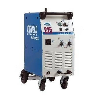
4.01 TRANSMIG 225, 255 MIG Power Source, 255 2R Wirefeeder
Overview of the TRANSMIG 225/255 MIG Power Source and 255 2R Wirefeeder, highlighting features and intended use.
4.02 User Responsibility
Outlines the user's responsibility for correct installation, operation, maintenance, and unauthorized modifications.
4.03 Duty Cycle
Explanation of the duty cycle rating for the welding power source and its implications for operation.
Safe Practices For The Use Of Welding Equipment
5.01 Precautions to be Taken by Operators
Essential safety precautions for operators to prevent electrical shock and other hazards during welding.
5.02 Personal Protection
Details necessary personal protective equipment (PPE) like gloves, clothing, and face shields for welding safety.
Resuscitation For Electric Shock Victims
6.01 Resuscitation
Step-by-step instructions for performing resuscitation on victims of electric shock, including CPR.
Specifications
7.01 TRANSMIG 225, 255 MIG Power Source Specifications
Detailed technical specifications for the TRANSMIG 225 and 255 MIG Power Sources, including ratings and dimensions.
7.02 Optional Accessories
List of available optional accessories for the TRANSMIG welding equipment, including part numbers.
Installation Recommendations
8.01 Environment
Guidelines for suitable operating environments, considering hazards like electric shock and conductive elements.
8.02 Location
Recommendations for locating the welding unit, considering factors like moisture, dust, and ventilation.
8.03 Ventilation
Emphasis on ensuring adequate ventilation in the welding area to remove harmful fumes and gases.
8.04 Mains Supply Voltage Requirements
Specifies the mains supply voltage requirements, fuse sizes, and lead sizes for optimal performance and safety.
Set up for the TRANSMIG 225, 255 MIG Power Source
9.01 Power Source Connections
Steps for connecting the power source, including work lead and gas cylinder setup.
9.02 Wirefeeder Connections (Remote models only)
Instructions for connecting the wirefeeder to the power source for remote operation.
9.03 Wirefeeder Connections (Compact models only)
Instructions for connecting the wirefeeder integrated into the power source for compact operation.
9.04 Common Connections
Procedure for threading electrode wire through the wire feeder system and into the MIG torch.
9.05 Drive Roller Pressure Adjustment
Guidance on adjusting the drive roller pressure for satisfactory wire feeding without slippage or excessive wear.
9.06 Wire Reel Brake
Instructions for adjusting the wire reel brake to prevent spool unwinding and tangling.
9.07 Wire Reel Hub Assembly
Details the assembly components of the wire reel hub, including part numbers for identification.
Power Source and Wirefeeder Controls, Indicators and Features
10.01 Standby switch with in-built Indicator Light
Description of the standby switch and indicator light, showing mains power connection status.
10.02 Wirespeed Control
Explains the wirespeed control knob's function in regulating welding current via electrode wirefeed rate.
10.03 Output Voltage Control Switch (Coarse)
Details the coarse voltage control switch for adjusting welding voltage in larger increments.
10.04 Output Voltage Control Switch (Fine)
Details the fine voltage control switch for adjusting welding voltage in smaller increments.
10.05 Torch Polarity Lead (Compact models only)
Explains the torch polarity lead for selecting welding voltage polarity for different electrode wires.
10.06 Positive Welding Terminal
Description of the positive welding terminal for connecting the welding current output.
10.07 Negative Welding Terminal
Description of the negative welding terminal for connecting the welding current output.
10.08 Torch Connector (Compact models only)
Location where the MIG torch connects to the compact power source.
10.09 Thermal Overload
Information on the thermal overload protection feature and its indication on the power source.
10.10 Spot Selector Switch
Switch for selecting the spot welding mode for joining two plates at a specific location.
10.11 Spot Timer
Control knob for setting the duration of a single spot weld when the spot selector is engaged.
10.12 Wirefeeder Control Socket (Remote model only)
Details the 7-pin receptacle for connecting a wirefeeder to the power source circuitry.
250A TWECO MIG Torch OTWX212/3035 (where supplied)
11.01 MIG Torch Components
List and identification of the various components that make up the 250A TWECO MIG Torch.
11.02 MIG Torch Contact Tips
Table listing part numbers for MIG torch contact tips corresponding to different wire sizes.
11.03 MIG Torch Conduits
Table listing part numbers for MIG torch conduits for hard and soft electrode wires.
11.04 Installing a new Wire Conduit
Step-by-step instructions for installing a new wire conduit into the MIG torch cable assembly.
11.05 MIG Torch Maintenance
Recommended weekly maintenance for the MIG torch conduit to prevent wire feeding issues.
Basic Welding Technique
12.01 Setting of the Power Source & Wirefeeder
Guidance on balancing wirespeed and voltage controls for optimal welding current and arc length.
12.02 Position of MIG Torch
Explanation of how the MIG torch angle affects the weld width during the welding process.
12.03 Distance from the MIG Torch Nozzle to the Work Piece
Recommended stick-out distance for the electrode wire from the MIG torch nozzle to the workpiece.
12.04 Travel Speed
Information on how travel speed influences the weld bead width and penetration.
12.05 Electrode Wire Size Selection
Factors to consider when selecting electrode wire size and shielding gas for different applications.
Routine Maintenance & Inspection
13.01 Cleaning the Feed Rolls
Instructions for cleaning the drive rolls and grooves to ensure proper wire feeding performance.
Basic Troubleshooting
14.02 Solving Problems Beyond the Welding Terminals - Porosity
Troubleshooting guide for weld porosity, identifying causes related to gas supply and contamination.
14.03 Solving Problems Beyond the Welding Terminals – Inconsistent Wire Feed
Troubleshooting guide for inconsistent wire feed issues, covering spool brake, rollers, and liner problems.
14.04 Welding Problems
Common welding problems like undercut, lack of penetration, and weld cracking, with their causes and remedies.
14.05 Power Source / Wirefeeder Problems
Troubleshooting issues related to the power source and wirefeeder operation, including indicator lights and trigger functions.
Need help?
Do you have a question about the 255 and is the answer not in the manual?
Questions and answers