
Related Manuals for CIGWELD 200 Pi Transtig


Summary of Contents for CIGWELD 200 Pi Transtig
-
Page 1: Service Manual
200 Pi ® TRANSTIG INVERTER ARC WELDER Service Manual Revision No: AA Issue Date: March 31, 2008 Manual No.: 0-4967 Operating Features: INVERTER... - Page 2 WE APPRECIATE YOUR BUSINESS! Congratulations on your new Cigweld product. We are proud to have you as our customer and will strive to provide you with the best service and reliability in the industry. This product is backed by our extensive warranty and world-wide service network. To locate your nearest distributor or service agency call 1300-654-674, or visit us on the web at www.cigweld.com.au.
- Page 3 WARNINGS Read and understand this entire Manual and your employer’s safety practices before installing, operating, or servicing the equipment. While the information contained in this Manual represents the Manufacturer's best judgement, the Manufacturer assumes no liability for its use. Transtig 200Pi Inverter Arc Welder Instruction Manual Number 0-4967 for: Catalog Number 700720 Published by:...
-
Page 4: Table Of Contents
TABLE OF CONTENTS SECTION 1: ARC WELDING SAFETY INSTRUCTIONS AND WARNINGS ........1-1 1.01 Arc Welding Hazards ..................1-1 1.02 PRINCIPAL SAFETY STANDARDS ..............1-5 1.03 DECLARATION OF CONFORMITY ..............1-6 SECTION 2: INTRODUCTION ..................2-1 2.01 How To Use This Manual ................2-1 2.02 Equipment Identification ................. - Page 5 TABLE OF CONTENTS TABLE OF CONTENTS (continued) SECTION 5: SERVICE ....................5-1 5.01 Routine Maintenance ..................5-1 5.02 Maintenance Diagram..................5-2 5.03 Basic Troubleshooting ..................5-3 5.04 TIG Welding Problems ................... 5-4 5.05 Stick Welding Problems ................. 5-6 5.06 Power Source Problems ................. 5-9 5.07 Power Source Error Codes ................
- Page 6 APPENDIX 3: CONNECTION WIRING GUIDE ............A-6 APPENDIX 4: INTERCONNECT DIAGRAM ............... A-8 APPENDIX 5: DIODE TESTING BASICS ..............A-10 CIGWELD LIMITED WARRANTY Terms of Warranty – December 2007 Warranty Schedule – December 2007 GLOBAL CUSTOMER SERVICE CONTACT INFORMATION ......Inside Rear Cover...
-
Page 7: Arc Welding Safety Instructions And Warnings
SERVICE MANUAL TRANSTIG 200 Pi SECTION 1: ARC WELDING SAFETY INSTRUCTIONS AND WARNINGS WARNING PROTECT YOURSELF AND OTHERS FROM POSSIBLE SERIOUS INJURY OR DEATH. KEEP CHILDREN AWAY. PACEMAKER WEARERS KEEP AWAY UNTIL CONSULTING YOUR DOCTOR. DO NOT LOSE THESE INSTRUCTIONS. READ OPERATING/INSTRUCTION MANUAL BEFORE INSTALLING, OPERATING OR SERVICING THIS EQUIPMENT. - Page 8 TRANSTIG 200 Pi SERVICE MANUAL WARNING WARNING FUMES AND GASES can be hazardous to ARC RAYS can burn eyes and skin; NOISE your health. can damage hearing. Welding produces fumes and gases. Arc rays from the welding process Breathing these fumes and gases can be produce intense heat and strong ultraviolet hazardous to your health.
- Page 9 SERVICE MANUAL TRANSTIG 200 Pi WARNING WARNING FLYING SPARKS AND HOT METAL can WELDING can cause fire or explosion. cause injury. Sparks and spatter fly off from the welding Chipping and grinding cause flying metal. arc. The flying sparks and hot metal, weld As welds cool, they can throw off slag.
- Page 10 TRANSTIG 200 Pi SERVICE MANUAL WARNING WARNING MOVING PARTS can cause injury. Engines can be dangerous. Moving parts, such as fans, rotors, and belts can cut fingers and hands and catch loose clothing. WARNING 1. Keep all doors, panels, covers, and guards closed and securely in place.
-
Page 11: Principal Safety Standards
SERVICE MANUAL TRANSTIG 200 Pi 1. Keep cables close together by twisting or taping them. 2. Arrange cables to one side and away from the WARNING operator. 3. Do not coil or drape cable around the body. STEAM AND PRESSURIZED HOT 4. -
Page 12: Declaration Of Conformity
71 Gower St, Preston Victoria 3072 Australia Description of equipment: Welding Equipment (GMAW, MMAW, GTAW). Including, but not limited to CIGWELD Transtig 200 Pi, Transtig 200 AC/DC, Transarc 300 Si, Transtig 300 Pi, Transtig 300 AC/DC, Transmig 400 i and associated accessories. -
Page 13: Introduction
Acrobat PDF format by when using this Service Manual. going to the Cigweld web site listed below and clicking on the Literature Library link: http://www.cigweld.com.au March 31, 2008... -
Page 14: Symbol Chart
TRANSTIG 200 Pi SERVICE MANUAL 2.04 Symbol Chart Note that only some of these symbols will appear on your model. Single Phase Wire Feed Function Wire Feed Towards Workpiece With Three Phase Output Voltage Off. Three Phase Static Frequency Converter- Welding Gun Dangerous Voltage Transformer-Rectifier... -
Page 15: Description
SERVICE MANUAL TRANSTIG 200 Pi 2.05 Description The Cigweld Transtig 200 Pi is a self contained single- phase DC arc welding power source with Constant Current (CC) output characteristics. This unit is equipped with a Digital Volt/Amperage Meter, gas control valve, built in Sloper and Pulser, lift arc starter,... -
Page 16: Functional Block Diagrams
TRANSTIG 200 Pi SERVICE MANUAL 2.06 Functional Block Diagrams Figure 2-2 illustrates the functional block diagram of the Transtig 200 Pi power source. Input Hall Current Main Input IGBT Main Output Capacitor Circuit Diode Inverter Transformers Transformer Diodes Power Switch Filter DC Power (HCT1) -
Page 17: Specifications
Table 2-1: Specifications Cigweld continuously strives to produce the best product possible and therefore reserves the right to change, improve or revise the specifications or design of this or any product without prior notice. Such updates or changes do not entitle the buyer of equipment previously sold or shipped to the corresponding changes, updates, improvements or replacement of such items. - Page 18 TRANSTIG 200 Pi SERVICE MANUAL THIS PAGE LEFT INTENTIONALLY BLANK. March 31, 2008...
-
Page 19: Installation
· In areas, not exposed to direct sunlight or rain. · Place at a distance of 12” (304.79mm) or more from walls or similar that could restrict natural airflow for cooling. WARNING Cigweld advises that this equipment be electrically connected by a qualified electrician. March 31, 2008... -
Page 20: Mains Supply Voltage Requirements
• Connected to the correct size 240V Mains Current Circuit as per the Specifications WARNING CIGWELD advises that this equipment be electrically connected by a qualified electrical trades- person. The following 240V Mains Current Circuit recommendations are required to obtain the maximum welding... -
Page 21: High Frequency Introduction
SERVICE MANUAL TRANSTIG 200 Pi 3.05 High Frequency Introduction 3.06 High Frequency Interference The importance of correct installation of high Interference may be transmitted by a high frequency frequency welding equipment cannot be initiated or stabilized arc welding machine in the overemphasized. -
Page 22: Duty Cycle
TRANSTIG 200 Pi SERVICE MANUAL 3.07 Duty Cycle CAUTION The duty cycle of a welding power source is the percentage of a ten (10) minute period that it can be Continually exceeding the duty cycle operated at a given output without causing ratings can cause damage to the welding overheating and damage to the unit. -
Page 23: Operation
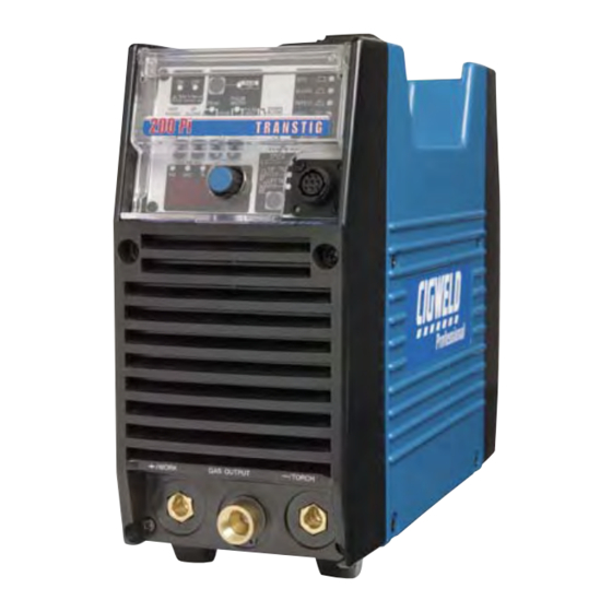
SERVICE MANUAL TRANSTIG 200 Pi SECTION 4: OPERATION 4.01 Transtig 200 Pi Controls Art # A-08343 Figure 4-1: Transtig 200 Pi Power Source 1. Control Knob: This control sets the selected weld Socket Function parameter, rotating it clockwise increases the parameter and is indicated on the digital meter. -
Page 24: Weld Process Selection For Transtig 200 Pi
TRANSTIG 200 Pi SERVICE MANUAL CAUTION WARNING Loose welding terminal connections can When the welder is connected to the cause overheating and result in the male Primary supply voltage, the internal plug being fused in the bayonet terminal. electrical components maybe at 240V potential with respect to earth. -
Page 25: Weld Parameter Descriptions For Transtig 200 Pi
SERVICE MANUAL TRANSTIG 200 Pi 4.03 Weld Parameter Descriptions for Transtig 200 Pi Art # A-06032_AB Figure 4-3: Transtig 200 Pi Front Panel Parameter Description This parameter operates in TIG modes only and is used to get gas to the weld zone PRE-FLOW prior to striking the arc, once the torch trigger switch has been pressed. -
Page 26: Weld Parameters For Transtig 200 Pi
TRANSTIG 200 Pi SERVICE MANUAL Parameter Description This parameter operates in TIG modes only and is used to set the time for the weld CRATER current to ramp down, after the torch trigger switch has been pressed, to DOWN SLOPE CUR. -
Page 27: Power Source Features
SERVICE MANUAL TRANSTIG 200 Pi 4.05 Power Source Features Feature Description New Digital Control Almost all welding parameters are adjustable Touch Panel Switches Touch switches eliminate mechanical damage Front Control Cover Protects front panel controls Digital Meter Displays selected weld parameter value Displays weld current when welding Displays weld current for 20 seconds after weld has been completed... - Page 28 TRANSTIG 200 Pi SERVICE MANUAL Feature Description Voltage Reduction Device (VRD) Reduces the OCV when the power supply is not in use. Eliminates the need for add on voltage reducers and has no effect on arc starting. VRD fully complies to AS 60974.1 When Stick mode is selected the green VRD light is ON when not welding and red when welding.
-
Page 29: Set-Up For Smaw (Stick) And Gtaw (Tig)
SERVICE MANUAL TRANSTIG 200 Pi 4.06 Set-Up for SMAW (STICK) and GTAW (TIG) Conventional operating procedures apply when using the Welding Power Source, i.e. connect work lead directly to work piece and electrode lead is used to hold electrode. Wide safety margins provided by the coil design ensure that the Welding Power Source will withstand short-term overload without adverse effects. -
Page 30: Sequence Of Operation
TRANSTIG 200 Pi SERVICE MANUAL 4.07 Sequence of Operation NOTE Scroll Buttons are used to select the parameters to be set. The LED’s show which function is being adjusted on the weld sequence graph. Refer to Symbols Table located in the front of the manual for Symbol descriptions. -
Page 31: Stick Welding
SERVICE MANUAL TRANSTIG 200 Pi 4.08 Stick Welding 4.09 HF TIG & Lift TIG Welding · Connect work lead to negative terminal · Connect work lead to positive terminal · Connect electrode lead to positive terminal · Connect TIG torch to negative terminal ·... -
Page 32: Slope Mode Sequence
TRANSTIG 200 Pi SERVICE MANUAL 4.10 Slope Mode Sequence Switch Switch Switch Switch Open Closed Open Closed Down Weld Current Slope Slope Initial Final Art # A-05069_AB Current Current Preflow Postflow Figure 4-6: Slope Mode Sequence 1) To start Slope sequence Close remote switch 2) Open Remote Switch: current increases to weld contacts. -
Page 33: Pulse Controls
SERVICE MANUAL TRANSTIG 200 Pi 4.12 Pulse Controls (Pulse Width) (Pulse Frequency) Art # A-05070 (Peak Current) (Base) Background Current Figure 4-7: Pulse Controls Pulse-current provides a system in which the welding The Pulse controls are used primarily to control heat current continuously changes between two levels. -
Page 34: Basic Tig Welding Guide
TRANSTIG 200 Pi SERVICE MANUAL 4.13 Basic TIG Welding Guide 1. Electrode Polarity: Connect the TIG torch to the - / TORCH terminal and the work lead to the + / WORK terminal for direct current straight polarity. Direct current straight polarity is the most widely used polarity for DC TIG welding. It allows limited wear of the electrode since 70% of the heat is concentrated at the work piece. - Page 35 SERVICE MANUAL TRANSTIG 200 Pi 5. Shielding Gas Selection: Alloy Shielding Gas Aluminium & alloys Argon Carbon Steel Argon Stainless Steel Argon Copper Argon Table 4-10: Shielding Gas Selection 6. TIG Welding Parameters for Low Carbon & Low Alloy Steel Pipe: Electrode Type Current Range Fillet Rod for...
-
Page 36: Basic Arc Welding Guide
TRANSTIG 200 Pi SERVICE MANUAL 4.14 Basic Arc Welding Guide C. Cast Iron Most types of cast iron, except white iron, are 1. Electrode Polarity: weldable. White iron, because of its extreme Stick electrodes are generally connected to the ‘+’ brittleness, generally cracks when attempts terminal and the work lead to the ‘-’... -
Page 37: Service
SERVICE MANUAL TRANSTIG 200 Pi SECTION 5: SERVICE 5.01 Routine Maintenance The only routine maintenance required for the power supply is a thorough cleaning and inspection, with the frequency depending on the usage and the operating environment. WARNING Disconnect primary power at the source before opening the enclosure. Wait at least two minutes before opening the enclosure to allow the primary capacitors to discharge. -
Page 38: Maintenance Diagram
Replace all exterior broken parts of power supply 6 Months Bring the unit to an authorized CIGWELD Service Provider to remove any accumulated dirt and dust from the interior. This may need to be done more frequently under exceptionally dirty conditions. -
Page 39: Basic Troubleshooting
WARNING There are extremely dangerous voltages and power levels present inside this product. Do not attempt to open or repair unless you are an Accredited Cigweld Service Provider and you have had training in power measurements and troubleshooting techniques. If major complex subassemblies are faulty, then the Welding Power Source must be returned to an Accredited Cigweld Service Provider for repair. -
Page 40: Tig Welding Problems
TRANSTIG 200 Pi SERVICE MANUAL 5.04 TIG Welding Problems Weld quality is dependent on the selection of the correct consumables, maintenance of equipment and proper welding technique. Description Possible Cause Remedy 1 Excessive bead build-up or poor Welding current is too low Increase weld current penetration or poor fusion at edges and/or faulty joint... - Page 41 SERVICE MANUAL TRANSTIG 200 Pi Description Possible Cause Remedy 10 Arc flutters during TIG welding A Tungsten electrode is too A Select the right size large for the welding current electrode. Refer to Basic TIG Welding Guide B Absence of oxides in the B Refer to Basic TIG weld pool Welding Guide for ways to...
-
Page 42: Stick Welding Problems
TRANSTIG 200 Pi SERVICE MANUAL 5.05 Stick Welding Problems Description Possible Cause Remedy 1 Gas pockets or voids in weld metal A Electrodes are damp A Dry electrodes before use (Porosity) B Welding current is too high B Reduce welding current C Surface impurities such as C Clean joint before welding oil, grease, paint, etc... - Page 43 SERVICE MANUAL TRANSTIG 200 Pi Description Possible Cause Remedy 4 Portions of the weld run do not A Small electrodes used on A Use larger electrodes and fuse to the surface of the metal or heavy cold plate preheat the plate edge of the joint B Welding current is too low B Increase welding current...
- Page 44 TRANSTIG 200 Pi SERVICE MANUAL Description Possible Cause Remedy 5 Non-metallic particles are trapped A Non-metallic particles may A If bad undercut is in the weld metal (slag inclusion) be trapped in undercut from present, clean slag out previous run and cover with a run from a smaller diameter electrode...
-
Page 45: Power Source Problems
B Switch ON the Welding switch is switched OFF Power Source C Loose connections C Have an Accredited internally Cigweld Service Provider repair the connection 2 Maximum output welding current Defective control circuit Have an Accredited cannot be achieved with nominal... - Page 46 B Gas valve is faulty B Have an Accredited Cigweld Service Provider replace gas valve C Gas valve jammed open C Have an Accredited Cigweld Service Provider repair or replace gas valve...
-
Page 47: Power Source Error Codes
TH1 B Fan ceases to operate B Have an Accredited (protects IGBTs) decreases to 70°C Cigweld Service Provider is greater than for about 30 seconds investigate 80 ° C for about 1 C Air flow is restricted by... - Page 48 Possible Cause Remedy Remarks 6 E94 error code The Welding Power Have an Accredited Weld current displayed. Source's temperature Cigweld Service Provider ceases. Buzzer Temperature sensors have check or replace the sounds constantly. sensor TH1 for malfunctioned temperature sensors Switch machine off.
-
Page 49: Voltage Reduction Device (Vrd)
In addition to the above tests and specifically in relation to the VRD fitted to this machine, the following periodic tests should also be conducted by an accredited Cigweld Service Provider. Description Required Parameters VRD Open Circuit Less than 20V;... - Page 50 TRANSTIG 200 Pi SERVICE MANUAL THIS PAGE LEFT INTENTIONALLY BLANK. 5-14 March 31, 2008...
-
Page 51: Advanced Troubleshooting
SERVICE MANUAL TRANSTIG 200 Pi ADVANCED TROUBLESHOOTING System-Level Fault Isolation ADVANCED TROUBLESHOOTING If you are here, all of the troubleshooting sugges- tions in Section 5 - Basic Troubleshooting have either failed to resolve the faulty operation or have indi- cated that one or more of the subsystems within If none of the suggestions provided in Section 8 the power supply are defective. - Page 52 TRANSTIG 200 Pi ADVANCED TROUBLESHOOTING SERVICE MANUAL 3) Loosen the screws on the front panel and the 5) Remove the side panels. rear panel by turning them approximately two turns CCW. NOTE DO NOT remove the screws completely. Figure 6-5: Remove Side Panel 6) Remove protection cover sheet by removing the plastic tabs.
-
Page 53: Verification And Remedy To The Indicated Error Codes
SERVICE MANUAL ADVANCED TROUBLESHOOTING TRANSTIG 200 Pi Verification and Remedy c) Verify the operation of the cooling fan, FAN1, and replace it if necessary. to the Indicated Error Codes Verify the condition of FAN1. Verify that there are no broken or cracked fan blades and that NOTE FAN1 is not producing any abnormal sounds. -
Page 54: E03 "Primary Over-Current Failure
TRANSTIG 200 Pi ADVANCED TROUBLESHOOTING SERVICE MANUAL 6.2.4 E94 “Thermistor malfunction” c) Verify the operation of the cooling fan, FAN1, and replace it if necessary. Cause Verify the condition of FAN1. Verify that there are no broken or cracked fan blades and that Thermistors for detecting temperature of internal FAN1 is not producing any abnormal sounds. -
Page 55: E04 "Torch Cable Failure
SERVICE MANUAL ADVANCED TROUBLESHOOTING TRANSTIG 200 Pi 6.2.7 E93 "Memory chip (EEPROM) 6.2.6 E04 "Torch Cable Failure" error." Cause The combined length of the torch cable and the Cause work cable is too long. Memory chip (EEPROM) on control PCB can not read/write weld parameters. -
Page 56: Cooling Fan (Fan1) Failure" (Fan Is Not Rotating.)
SERVICE MANUAL ADVANCED TROUBLESHOOTING TRANSTIG 200 Pi 6.3.2 “Gas Valve Failure” Verification and Remedy to Failures without (No Gas flow through unit) Indication Codes Cause Occurs when the gas valve (SOL1) is defective, Refer to Note on Section 11.02. damaged or the driving voltage is incorrect. 6.3.1 “Cooling Fan (FAN1) Failure”... -
Page 57: No Weld Output
TRANSTIG 200 Pi ADVANCED TROUBLESHOOTING SERVICE MANUAL 6.3.3 “No weld output” Refer to the section “Verification of No-load voltage (No OCV)” in the page 6-13. When in High Frequency TIG (HF TIG) mode, if the If performing the “No-Load Voltage Failure” High Frequency is not generated (present), refer to procedure does not rectify the failure, per- “High Frequency Output Failure”. -
Page 58: High Frequency Output Failure
SERVICE MANUAL ADVANCED TROUBLESHOOTING TRANSTIG 200 Pi b) Verify the connection between PCB5 (WK- Verify there are no short circuits, burnt or bro- 5448) and PCB4 (WK-5460). ken wires between the HF UNIT1 and the R3 (R4). Verify that there is no omission of a loosening screws and connected harness between the c) Verify the connection between the terminals PCB4 and PCB5. -
Page 59: Fault Isolation Tests
TRANSTIG 200 Pi ADVANCED TROUBLESHOOTING SERVICE MANUAL Fault Isolation Tests Verification of the Power Input Circuitry 6.4.1 Preparation The following initial conditions must be met prior to CAUTION starting any of the procedures in this section. Before performing any portion of the procedure below, make certain the unit is placed in the initial set up condition as described in section 6.4.1 1) Connect the appropriate input voltage. -
Page 60: Verification Of Power Supply Voltage
SERVICE MANUAL ADVANCED TROUBLESHOOTING TRANSTIG 200 Pi points U2 and V2 on the input switch, S1. The location of points U2 and V2 on switch S1 are indicated in Figure 6-7. 4) If this voltage is out of the operating range, which is ±10% (207~253VAC) of the rated volt- age (230V), replace S1 following the process in section 12.3-4. -
Page 61: Verification Of The Cooling Fan, Fan1, Drive Circuitry
TRANSTIG 200 Pi ADVANCED TROUBLESHOOTING SERVICE MANUAL 6.5.3 Verification of the Cooling Test Point Reference ACCEPTABLE Fan, FAN1, Drive Circuitry PCB6 PCB6 VALUE +5VDC CAUTION +12VDC –12VDC Before performing any portion of the procedure below, make certain the unit is placed in the initial Table 6-1: Checkpoints TP0-TP3 on PCB6 set up condition as described in section 6.4.1 "Preparation". -
Page 62: Verification Of The Gas Valve, Sol1, Drive Circuitry
SERVICE MANUAL ADVANCED TROUBLESHOOTING TRANSTIG 200 Pi Voltage FAN1 measurement. Remedy Status (1PIN-2PIN of CN2 on PCB1) PCB1(WK-5713) Replace PCB1. Refer to the page 7-5. Perform Case 3 Inactive Below DC 18V “2. Verification of the Power Supply Voltage Test”. Refer to the page 6-9. -
Page 63: Verification Of The Secondary Diode (D2, D3)
TRANSTIG 200 Pi ADVANCED TROUBLESHOOTING SERVICE MANUAL 2) Refer to Table 11-5 and Figure 11-14 for TERMINALS the checkpoints on D1. COMPONENT ACCEPTABLE Positive Negative TESTED VALUE lead lead TERMINALS COMPONENT ACCEPTABLE Diode 1 of D2, Anode Cathode 0.2 to 0.3V Positive Negative TESTED... -
Page 64: Verification Of No-Load Voltage (Ocv)
SERVICE MANUAL ADVANCED TROUBLESHOOTING TRANSTIG 200 Pi a) Verify the no-load voltage in STICK mode. TERMINALS 1) In STICK welding mode, mark and then COMPONENT ACCEPTABLE Positive Negative TESTED VALUE turn potentiometer VR1 on PCB4 (WK- lead lead 5449) all the way to the right and turn off Collector-Emitter the electric shock protector function (Volt- Open... - Page 65 TRANSTIG 200 Pi ADVANCED TROUBLESHOOTING SERVICE MANUAL 2) Press the Welding mode selection button to select HF TIG welding mode. 3) While depressing the Torch switch, verify the OCV using a DC voltmeter. (The capability of the voltmeter should be more than 100VDC.) The check point with a tester is the voltage between output termi- nal + and -.
-
Page 66: Maintenance
SERVICE MANUAL TRANSTIG 200 Pi 7 MAINTENANCE MAINTENANCE Subsystem Test and Replacement Procedures 7.1.1 Preparation This section provides specific procedures for verifying the operation and replacement of each subsystem within the power supply. Before undertaking any of these procedures, eliminate the obvious first-visually inspect the suspect sub- system for physical damage, overheating, and loose connections. - Page 67 TRANSTIG 200 Pi MAINTENANCE SERVICE MANUAL REFERENCE DWG NO. PARTS NAME PART NO. PAGE Capacitor 12-8 10-6510 C101-C102 Capacitor 12-21 W7001622 C103 Capacitor 12-24 W7001621 Capacitor 12-25 W7001620 C.C. Coupling Coil 12-15 W7001384 FCH1 Reactor 12-15 W7001502 HF - UNIT High Freguency Unit 12-19 W7001399...
- Page 68 SERVICE MANUAL MAINTENANCE TRANSTIG 200 Pi REFERENCE DWG NO. PARTS NAME PARTNO. PAGE 12-22 10-6627 CON1 Remote Receptacle 12-17 10-5003 Hall Current Trans 12-5 W7001481 Primary Diode 12-15 10-6629 Secondary Diode 12-15 10-6629 Secondary Diode 12-18 10-5227 FAN1 Cooling Fan 12-21 W7001453 Switch...
-
Page 69: Service Tools
TRANSTIG 200 Pi MAINTENANCE SERVICE MANUAL Service Tools 7.2.1 Tools and parts The tools and parts to be used for maintenance are shown by icons. Philips Head Long Nose Soldering Copper Silicon Spanner C-Ring Pliers Snap Band Screwdriver Compound (solder) Pliers 7.2.2 Notes of disassembly and assembly NOTE... -
Page 70: Replacement Procedure
SERVICE MANUAL MAINTENANCE TRANSTIG 200 Pi Replacement Procedure 7.3.1 PCB1 (WK-5713) and Primary Diode D1 1) Remove the Side Panel. [See section “6.1-1”] 2) Remove the L102. [See section “7.3-18”] 3) Remove the screw and three cables. Cut the snap band. 4) Remove the terminal and Disconnect the three connectors CN1 (PCB4), CN101, 103 (PCB1). - Page 71 TRANSTIG 200 Pi MAINTENANCE SERVICE MANUAL 6) Remove the Gas Tube. Remove the two bolts, two toothed washers, and the terminal. 7) Remove the four screws and the Front Panel. 8) Remove the Gas Tube and the two cables. 7 – 6...
- Page 72 SERVICE MANUAL MAINTENANCE TRANSTIG 200 Pi 9) Remove the four screws and the Rear Panel. 10) Remove the four screws and the two cables. Disconnect the eight connectors CN1-8 on the PCB1. CN4 CN5 CN6 CN8 CN7 11) Remove the four screws and Remove the PCB1 unit. 7 –...
-
Page 73: Pcb2 (Wk-5417), Capacitor C1 And Resistor R1
TRANSTIG 200 Pi MAINTENANCE SERVICE MANUAL 12) Remove the Primary Diode D1 with the soldering iron from the PCB1. Before installing a new diode, apply a uniform coat of silicone compound (Shinetsu Silicone G-747 or equivalent) on the base. 7.3.2 PCB2 (WK-5417), Capacitor C1 and Resistor R1 1) Remove the Side Panel. - Page 74 SERVICE MANUAL MAINTENANCE TRANSTIG 200 Pi 5) Remove the eight screws and the PCB2 unit. 6) Remove the screw and Remove the Capacitor C1 and Resistor R1 from the PCB2. Remove the two edge holders and the PCB2 Insulation Sheet from PCB2. 7 –...
-
Page 75: Pcb3 (Wk-5609) And T1 "Transformer
TRANSTIG 200 Pi MAINTENANCE SERVICE MANUAL 7.3.3 PCB3 (WK-5609) and T1 “Transformer” 1) Remove the Side Panel. [See section "6.1-1"] 2) Remove the CT1. [See section “7.3-10”] 3) Cut the snap band and Remove the cables. Disconnect the three connectors CN1-3 on the PCB3. Remove the three screws and the three cables. -
Page 76: Pcb4 (Wk-5449)
SERVICE MANUAL MAINTENANCE TRANSTIG 200 Pi 7.3.4 PCB4 (WK-5449) 1) Remove the Side Panel. [See section "6.1-1"] 2) Remove the Protection Cover. 3) Remove the Knob Cap. Holding the Knob down, loosen the screw and remove the Knob. 4) Disconnect the two connectors CN1,3 on the PCB4. Remove the four screws. Pull out the operation panel and bring it down. -
Page 77: Pcb5 (Wk-5548)
TRANSTIG 200 Pi MAINTENANCE SERVICE MANUAL 5) Remove the four screws. Remove the PCB4. 7.3.5 PCB5 (WK-5448) 1) Remove the Side Panel. [See section "11.1-1"] 2) Remove the PCB4. [See section “12.3-4”] 3) Remove the three latches of Front Control Cover and then remove the PCB5. When reinstalling the PCB5, engage two latches of Front Control Cover first. -
Page 78: Pcb6 (Wk-5460) And Q1A-Q2C "Primary Igbt
SERVICE MANUAL MAINTENANCE TRANSTIG 200 Pi 7.3.6 PCB6 (WK-5460) and Q1A-Q2C “Primary IGBT” 1) Remove the Side Panel. [See section "6.1-1"] 2) Remove the four screws and two IGBT Spring Clips. Remove the cables from edge holder. 3) Disconnect the connector CN1 on the PCB6. Cut the lead of the Q1A-Q2C. Remember to install new Silicone Rubber Sheets where silicone compound (Shinetsu Silicone G-747 or equivalent) was spread when reinstalling the PCB6. -
Page 79: 7Pcb7 (Wk-5460) And Q3A-Q4C "Primary Igbt
TRANSTIG 200 Pi MAINTENANCE SERVICE MANUAL 7.3.7 PCB7 (WK-5460) and Q3A-Q4C “Primary IGBT” 1) Remove the Side Panel. [See section “6.1-1”] 2) Remove the four screws and two IGBT Spring Clips. Remove the cables from edge holder. 3) Disconnect the connector CN1 on the PCB6. Cut the lead of the Q3-Q4C. Remember to install new Silicone Rubber Sheets where silicone compound (Shinetsu Silicone G-747 or equivalent) was spread when reinstalling the PCB7. -
Page 80: D2 And D3 "Secondary Diode
SERVICE MANUAL MAINTENANCE TRANSTIG 200 Pi 7.3.8 D2 and D3 “Secondary Diode” 1) Remove the Side Panel. [See section “6.1-1”] 2) Remove PCB3 (WK-5569) and T1. [See section “7.3-3”] 3) Remove six screws and then detach the D2 and D3. Do not have the wrong direction of the diodes when reinstalling. - Page 81 TRANSTIG 200 Pi MAINTENANCE SERVICE MANUAL 3) Remove the four screws and the Front Panel. 4) Remove the screw and then remove the cable. Remove the two terminals from HF. UNIT. Remove the terminal from PCB3. 5) Remove the C.C. and FCH1. 7 –...
-
Page 82: Ct1 "Hole Current Trans
SERVICE MANUAL MAINTENANCE TRANSTIG 200 Pi 7.3.10 CT1 “Hole Current Trans” 1) Remove the Side Panel. [See section “11.1-1”] 2) Remove the bolts, the spring, and the washer. Remove the three screws and then remove the Output Bus Bar. 3) Remove the CT1. Disconnect the connector. 7 –... -
Page 83: Fan1 "Cooling Fan
TRANSTIG 200 Pi MAINTENANCE SERVICE MANUAL 7.3.11 FAN1 “Cooling Fan” 1) Remove the Side Panel. [See section “6.1-1”] 2) Remove the Gas Tube. Remove the two terminals and Cut the three snap bands. 3) Disconnect the connector CN2 on the PCB1 and Cut the snap band. 4) Remove the four screws and then open the Rear Panel. -
Page 84: Hf Unit1 "High Frequency Unit
SERVICE MANUAL MAINTENANCE TRANSTIG 200 Pi 5) Remove the FAN1. Do not have the wrong direction of the fan when reinstalling. 7.3.12 HF UNIT1 “High Frequency Unit” 1) Remove the Side Panel. [See section “6.1-1”] 2) Remove the high frequency gap. Remove the four terminals. 3) Remove the two screws and the two washers. -
Page 85: Sol1 "Solenoid Gas Valve
TRANSTIG 200 Pi MAINTENANCE SERVICE MANUAL 7.3.13 SOL1 “Solenoid GAS Valve” 1) Remove the Side Panel. [See section “6.1-1”] 2) Remove the Gas Tube and two terminals. 3) Remove the C-ring and then detach the SOL1. When reinstalling, make sure that the C-ring seats in the solenoid valve groove. 7 –... -
Page 86: C101-C102 "Capacitor", L101 "Ring Core" And S1 "Switch
SERVICE MANUAL MAINTENANCE TRANSTIG 200 Pi 7.3.14 C101-C102 “Capacitor”, L101 “Ring Core” and S1 “Switch” 1) Remove the Side Panel. [See section “6.1-1”] 2) Remove the four screws and the six cables. Remove the one nut and one terminal. Remove the C101- C102. -
Page 87: Con1 "Remote Receptacle
TRANSTIG 200 Pi MAINTENANCE SERVICE MANUAL 7.3.15 CON1 “Remote Receptacle” 1) Remove the Side Panel. [See section “6.1-1”] 2) Remove the screw and then three ground cables. Cut the two snap bands. 3) Cut the snap band and disconnect connector CN1 on the PCB1. 4) Open the Panel Protects. -
Page 88: Th1 "Primary Thermistor
SERVICE MANUAL MAINTENANCE TRANSTIG 200 Pi 7.3.16 TH1 “Primary Thermistor” 1) Remove the Side Panel. [See section “6.1-1”] 2) Remove the snap band. Disconnect the connector CN5 on the PCB1. Remove the screw and then detach the TH1. Before installing a new Thermistor, apply a uniform coat of silicone compound (Shinetsu Silicone G-747 or equivalent) on the base. -
Page 89: C103 "Capacitor" And L102 "Reactor
TRANSTIG 200 Pi MAINTENANCE SERVICE MANUAL 7.3.18 C103 “Capacitor” and L102 “Reactor” 1) Remove the Side Panel. [See section “6.1-1”] 2) Remove four screws, six terminals. Remove the C103 and L102. Note : When C103 is installed again, it is a thing fixed to former place on PCB3 by RTV silicon rubber. 7.3.19 L103 “Reactor”... -
Page 90: C2 "Capacitor" And R2 "Resistor
SERVICE MANUAL MAINTENANCE TRANSTIG 200 Pi 4) Remove four screws and open the Rear Control Cover. 5) Remove one nut, one washer and two terminals. Remove the L103. 7.3.20 C2 “Capacitor” and R2 “Resistor” 1) Remove the Side Panel. [See section “6.1-1”] 2) Remove the Gas Tube and the two cables. - Page 91 TRANSTIG 200 Pi MAINTENANCE SERVICE MANUAL 3) Remove the four screws and open the Rear Panel. 4) Remove the CT1. [See section “7.3-10”] 5) Cut the snap band and remove the cables. Disconnect the three connectors CN1-3 on the PCB3. Remove the three screws and the three cables.
- Page 92 SERVICE MANUAL MAINTENANCE TRANSTIG 200 Pi 7) Remove the screw and C2 unit. 8) Remove the C2 with the soldering iron from the R2. 7 – 27...
-
Page 93: Appendix 1: Options And Accessories
200Pi, 200AC/DC hand pendant only Hand pendant OTD 10/2005 300Pi, 300AC/DC, 400i hand pendant only OTD 10/4016 200Pi, 200AC/DC Foot controller OTD 10/2007 300Pi, 300AC/DC, 400i CIGWELD COMET argon regulator 301527 Regulator only CIGWELD COMET argon flowmeter 0-15 lpm 301710 Flowmeter only... -
Page 94: How To Use This Parts List
SERVICE MANUAL TRANSTIG 200 Pi APPENDIX 2: PARTS LIST Equipment Identification All identification numbers as described in the Introduction chapter must be furnished when ordering parts or making inquiries. This information is usually found on the nameplate attached to the equipment. Be sure to include any dash numbers following the Specificazztion or Assembly numbers. -
Page 95: Parts List
TRANSTIG 200 Pi SERVICE MANUAL PARTS LIST & R4-5 W7001452 Resistor, gen 3.1, IPS MHS20A221KI 20W 220Ω W7001451 Resistor, gen 3.1, IPS MHS20A101KI 20W 100Ω W7001453 Switch, gen 3.1, IPS DCP-52SR50C-480V 2P-480V (185ACDC) 5505NBR1.5 DC24V 11VA/10W (with Gas SOL1 W7001604 Solenoid Valve, gen 3.1, IPS Inlet and PC4-02) W7001456... - Page 96 SERVICE MANUAL TRANSTIG 200 Pi PARTS LIST & W7001616 Sheet, dust cover F, gen 3.1, IPS E1B935200 W7001609 Sheet, dust cover R, gen 3.1, IPS E1B935600 p i l , 1 . W7001618 Hose, Nylon, gen 3.1, IPS T0425B Nylon Hose L=0.5m , 1 .
-
Page 97: Appendix 2: Parts List
TRANSTIG 200 Pi SERVICE MANUAL PARTS LIST... -
Page 98: Appendix 3: Connection Wiring Guide
SERVICE MANUAL TRANSTIG 200 Pi APPENDIX 3: CONNECTION WIRING GUIDE CONNECTION WIRING GUIDE APPENDIX 2 Connection Wiring Guide Destination PCB2 PCB3 PCB2 PCB3 PCB3 PCB17 PCB3 FAN1 PCB3 CN11 SOL1 PCB3 CN20 PCB8 PCB3 CN21 PCB8 PCB3 CN22 PCB9 PCB3 CN23 PCB9 PCB3... - Page 99 TRANSTIG 200 Pi SERVICE MANUAL CONNECTION WIRING GUIDE CN21 PCB17 CN17 PCB6 CN20 FAN1 CN33 PCB4 SOL1 PCB10 PCB11 CN18 PCB7 CN11 CN15 CN20 CN22 CN14 CN20 CN23 CON1 CN21 PCB9 PCB3 PCB8 PCB16 PCB15 PCB2 HCT1 PCB13...
-
Page 100: Appendix 4: Interconnect Diagram
SERVICE MANUAL TRANSTIG 200 Pi APPENDIX 4: INTERCONNECT DIAGRAM APPENDIX 3 INTERCONNECT DIAGRAM INTERCONNECT DIAGRAM INTERCONNECT DIAGRAM PCB1 K(7) Main PCB8 Circuit IGBT Gate G(6) Board Circuit [WK-5477] Board R(3) PCB18 L101 [WK-5479] CE Filter Circuit Board S(4) [WK-5861] T(5) Ground Ground L103... - Page 101 TRANSTIG 200 Pi SERVICE MANUAL INTERCONNECT DIAGRAM PCB12 PCB14 DIODE Snubber IGBT Snubber Circuit Board Circuit Board [WK-5615] [WK-5570] FCH1 TB20 PCB15 TB22 IGBT Gate Circuit Board +Output TB12 [WK-3367] Terminal TB21 1 2 3 4 5 1 2 3 4 5 Ground PCB16 RY+15V...
-
Page 102: Appendix 5: Diode Testing Basics
SERVICE MANUAL TRANSTIG 200 Pi APPENDIX 5: DIODE TESTING BASICS DIODE TESTING BASIC APPENDIX 4 DIODE TESTING BASIC Testing of diode modules requires a digital Volt/ Ohmmeter that has a diode test scale.Locate the diode module to be tested.Remove cables from mounting studs on diodes to isolate them within the module.Set the digital volt/ohm meter to the diode test scale.Using figure 1 and 2, check each diode... -
Page 103: Cigweld Limited Warranty
“Purchaser” that its products will be free of defects in workmanship or material. Should any failure to conform to this warranty appear within the time period applicable to the CIGWELD products as stated below, CIGWELD shall, upon notification thereof and substantiation that the product has been stored, installed, operated, and maintained in accordance with CIGWELD’s specifications, instructions,... -
Page 104: Terms Of Warranty – December
CIGWELD. 4. CIGWELD declares that, to the extent permitted by law, it hereby limits its liability in respect of the supply of goods which are not of a kind ordinarily acquired for personal, domestic or household use or consump- tion to any one or more of the following (the choice of which shall be at the option of CIGWELD). -
Page 105: Warranty Schedule – December
Accredited Distributor of the equipment. Notwithstanding the foregoing, in no event shall the war- ranty period extend more than the time stated plus one year from the date CIGWELD delivered the product to the Accredited Distributor. Unless otherwise stated the warranty period includes parts and labour. CIGWELD reserves the right to request documented evidence of date of purchase. -
Page 107: Global Customer Service Contact Information
48000 Rawang Selangor Darul Ehsan 800-426-1888 West Malaysia Fax: 800-535-0557 Telephone: 603+ 6092 2988 Email: sales@thermalarc.com Fax : 603+ 6092 1085 Thermadyne Canada Cigweld, Australia 2070 Wyecroft Road 71 Gower Street Oakville, Ontario Preston, Victoria Canada, L6L5V6 Australia, 3072 Telephone: (905)-827-1111... - Page 108 Corporate Headquarters 71 Gower Street Preston, Victoria, Australia, 3072 Telephone: +61 3 9474 7400 FAX: +61 3 9474 7488 Email: cigweldsales@cigweld.com.au www.cigweld.com.au...
Need help?
Do you have a question about the 200 Pi Transtig and is the answer not in the manual?
Questions and answers