
Related Manuals for CIGWELD 250i Transmig


Summary of Contents for CIGWELD 250i Transmig
-
Page 1: Service Manual
250i TRANSMIG MULTI PROCESS WELDING INVERTER Service Manual Revision: AA Issue Date: September 14, 2012 Manual No.: 0-5188 Operating Features: 240 PFC... - Page 2 To locate your nearest distributor or service agency call +1300 654 674, or visit us on the web at www.cigweld.com. This Operating Manual has been designed to instruct you on the correct use and operation of your CIGWELD product.
- Page 3 While the information contained in this Manual represents the Manufacturer’s best judgement, the Manufacturer assumes no liability for its use. Operating Manual Number 0-5188 for: Cigweld Transmig 250i Inverter Power Source (South Pacific) Part Number W1003251 Cigweld Transmig 250i Inverter Plant (Asia) Part Number W1003250M Published by: Victor Technologies.
-
Page 4: Table Of Contents
TABLE OF CONTENTS SECTION 1: ARC WELDING SAFETY INSTRUCTIONS AND WARNINGS ......... 1-1 1.01 Arc Welding Hazards ....................1-1 1.02 Principal Safety Standards ..................1-5 1.03 Declaration of Conformity ..................1-6 SECTION 2: INTRODUCTION ................. 2-1 2.01 How to Use This Manual ..................2-1 2.02 Equipment Identification .................. - Page 5 TABLE OF CONTENTS SECTION 4: BASIC WELDING GUIDE ................4-1 4.01 MIG (GMAW/FCAW) Basic Welding Technique ............4-1 4.02 MIG (GMAW/FCAW) Welding Troubleshooting ............4-4 4.03 Stick (MMAW) Basic Welding Technique ..............4-7 4.04 Stick (MMAW) Welding Troubleshooting .............. 4-16 4.05 TIG (GTAW) Basic Welding Technique ..............
- Page 6 APPENDIX 1: OPTIONS AND ACCESSORIES ............... A-1 APPENDIX 2: TRANSMIG 250i CIRCUIT DIAGRAM ............A-2 CIGWELD LIMITED WARRANTY ................RC-2 CIGWELD TERMS OF WARRANTY – APRIL 2012 ............RC-3 WARRANTY SCHEDULE – APRIL 2010 ..............RC-4...
-
Page 7: Arc Welding Safety Instructions And Warnings
TRANSMIG 250i SECTION 1: ARC WELDING SAFETY INSTRUCTIONS AND WARNINGS WARNING PROTECT YOURSELF AND OTHERS FROM POSSIBLE SERIOUS INJURY OR DEATH. KEEP CHILDREN AWAY. PACEMAKER WEARERS KEEP AWAY UNTIL CONSULTING YOUR DOCTOR. Do NOT LOSE THESE INSTRUCTIONS. READ OPERATING/INSTRUCTION MANUAL BEFORE INSTALLING, OPERATING OR SERVICING THIS EQUIPMENT. Welding products and welding processes can cause serious injury or death, or damage to other equipment or property, if the operator does not strictly observe all safety rules and take precautionary actions. - Page 8 TRANSMIG 250i 2. Wear approved safety glasses. Side shields recom- mended. 3. Use protective screens or barriers to protect others WARNING from flash and glare; warn others not to watch the arc. ARC RAYS can burn eyes and skin; NOISE can 4.
- Page 9 TRANSMIG 250i 3. Remove all flammables within 10M of the welding arc. If this is not possible, tightly cover them with approved covers. WARNING 4. Be alert that welding sparks and hot materials from FUMES AND GASES can be hazardous to your welding can easily go through small cracks and open- health.
- Page 10 TRANSMIG 250i 4. Never allow a welding electrode to touch any cylinder. Frequency Electric & Magnetic Fields - Background Paper, OTA-BP-E-63 (Washington, DC: U.S. Government Printing 5. Use only correct shielding gas cylinders, regulators, Office, May 1989): “...there is now a very large volume hoses, and fittings designed for the specific application;...
-
Page 11: Principal Safety Standards
TRANSMIG 250i 1.02 Principal Safety Standards Safety in Welding and Cutting, ANSI Standard Z49.1, from American Welding Society, 550 N.W. LeJeune Rd., Miami, FL 33126. Safety and Health Standards, OSHA 29 CFR 1910, from Superintendent of Documents, U.S. Government Printing Office, Washington, D.C. -
Page 12: Declaration Of Conformity
Victoria 3072 Australia Description of equipment: Welding Equipment (GMAW, FCAW, GTAW, MMAW) including, but not limited to CIGWELD Transmig 250i Multi Process Welding Inverter, CIGWELD Transmig 2RT wire feeder and associated accessories. Serial numbers are unique with each individual piece of equipment and details description, parts used to manufacture a unit and date of manufacture. -
Page 13: Section 2: Introduction
Additional copies of this manual may be purchased by contacting CIGWELD at the address and phone number for your location listed in the inside back cover of this manual. Include the Owner’s Manual number and equip- ment identification numbers. -
Page 14: Symbol Chart
TRANSMIG 250i INTRODUCTION 2.04 Symbol Chart Note that only some of these symbols will appear on your model. Wire Feed Function Single Phase Wire Feed Towards Workpiece With Three Phase Output Voltage Off. Three Phase Static Frequency Converter- Welding Torch Dangerous Voltage Transformer-Rectifier Purging Of Gas... -
Page 15: Description
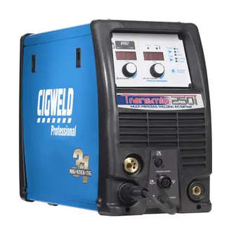
INTRODUCTION TRANSMIG 250i 2.07 Transportation Methods 2.05 Description The Cigweld Transmig 250i is a self contained single phase multi process welding inverter that is capable of perform- WARNING ing GMAW/FCAW (MIG), MMAW (Stick) and GTAW (Lift TIG) welding processes. The Transmig 250i is equipped ELECTRIC SHOCK can kill. -
Page 16: Packaged Items
TRANSMIG 250i INTRODUCTION 2.08 Packaged Items Transmig 250i MIG Plant - Asia (Part number W1003250M) Transmig 250i Plant - • Transmig 250i Inverter Power Source South Pacific (Part No. W1003250) • MIG Torch,Tweco Fusion 250A, 3.6M, Euro, STD • Transmig 250i Inverter Power Source • Leadset, 250A, 4M, 50D • MIG Torch,Tweco Fusion 250A, 3.6M, Euro, STD • Gas Hose, 3M, Female 3/8 BSP • Regulator / Flow Meter - COMET 250 ARG 55LPM 2GA • Operating Manual • Leadset, 250A, 4M, 50D • Drive Roll 'V' Knurled 1.2mm • Gas Hose, 3M • Drive Roll 'U' Groove 1.2mm • Operating Manual • Drive Roll 'V' Groove 0.6-0.9mm • Drive Roll 'V' Knurled 1.2mm • Drive Roll 'V' Groove 0.9-1.2mm, Fitted • Drive Roll 'U' Groove 1.2mm • Pressure Roll 0.6-1.2mm Solid Wire, Fitted • Drive Roll 'V' Groove 0.6-0.9mm... -
Page 17: Duty Cycle
INTRODUCTION TRANSMIG 250i 2.09 Duty Cycle The rated duty cycle of a Welding Power Source is a statement of the time it may be operated at its rated welding cur- rent output without exceeding the temperature limits of the insulation of the component parts. To explain the 10 minute duty cycle period the following example is used. -
Page 18: Specifications
TRANSMIG 250i INTRODUCTION 2.10 Specifications Description TRANSMIG 250i MULTI PROCESS WELDING INVERTER Power Source Dimensions H 440mm x W 260mm x D 600mm Power Source Mass 29.5kg Cooling Fan Cooled Welder Type Multi Process Inverter Power Source Australian Standard AS 60974.1-2006 / IEC60974.1 Number of Phases Single Phase Nominal Supply Voltage... -
Page 19: Section 3: Installation Operation And Setup
INSTALLATION/SETUP TRANSMIG 250i SECTION 3: INSTALLATION OPERATION AND SETUP G. The enclosure design of this power source meets the 3.01 Environment requirements of IP23S as outlined in AS60529. This These units are designed for use in environments with provides adequate protection against solid objects increased hazard of electric shock as outlined in AS (greater than 12mm), and direct protection from verti- cal drops. - Page 20 TRANSMIG 250i INSTALLATION/SETUP WARNING The Transmig 250i must be electrically connected by a qualified electrical trades-person. Damage to the PCA (Power Control Assembly) could occur if 276 VAC or higher is applied to the Primary Power Cable 50/60 Hz Primary Supply Minimum Minimum Current &...
-
Page 21: Electromagnetic Compatibility
INSTALLATION/SETUP TRANSMIG 250i 5. The health of people around, e.g. the use of pace- 3.05 Electromagnetic Compatibility makers and hearing aids. 6. Equipment used for calibration and measurement. 7. The time of day that welding or other activities are to WARNING be carried out. -
Page 22: Power Source Controls, Indicators And Features
TRANSMIG 250i INSTALLATION/SETUP 4. Equipotential Bonding Bonding of all metallic components in the welding installation and adjacent to it should be considered. However, metallic components bonded to the work piece will increase the risk that the operator could receive a shock by touching the metallic components and the electrode at the same time. - Page 23 INSTALLATION/SETUP TRANSMIG 250i 2. Power Indicator The green power indicator will be illuminated when the welder is turned ON and indicates the presence of power. 3. Fault Indicator The yellow fault indicator will be illuminated when any Art # A-10319 of the faults are detected.
- Page 24 TRANSMIG 250i INSTALLATION/SETUP 6. Advanced Features Button revert back to showing the weld current measurements when the knob is not being turned. 8. Right Knob: Multifunction Control - MIG Voltage / Arc Control (Inductance) & STICK Arc Force Press and release the Advanced Features button to enter or exit from the advanced programming mode.
- Page 25 INSTALLATION/SETUP TRANSMIG 250i To access the Arc Control function, push inward on the right knob and hold it for approximately 2 seconds. This feature can be accessed and adjusted during welding. The left display will change to show the Arc Control parameter name that is in effect for the current MIG or STICK Modes and the right display will show its present value.
- Page 26 TRANSMIG 250i INSTALLATION/SETUP At the completion of welding, the digital meter will hold the last recorded voltage value for a period of approximately 10 seconds in all modes. The voltage meter will hold the value until; (1) any of the front panel controls are adjusted in which case the unit will revert to preview mode, (2) welding is recommenced, in which case actual welding amperage will be displayed, or (3) a period of 10 seconds elapses following the completion of welding in which case the unit will return to preview mode.
- Page 27 INSTALLATION/SETUP TRANSMIG 250i 13. 10 Pin Accessories Socket The 10 pin Accessories Socket is used to connect remote devices such as 2RT wirefeeder to the welding power source. To make connections, align keyway, insert plug, and rotate threaded collar fully clockwise. Peripheral Resistor Trigger...
-
Page 28: Advanced Features Details
TRANSMIG 250i INSTALLATION/SETUP 15. Negative Welding Output Terminal The negative welding terminal is used to connect the welding output of the power source to the appropriate Then press and release the Advanced welding accessory such as the MIG Torch (via the MIG Features button (Control No 6) to enter or Torch polarity lead), TIG torch or work lead. - Page 29 INSTALLATION/SETUP TRANSMIG 250i LIFT TIG If the welder is in Advanced Features mode and the Weld Process Selection button (Control No 4) is pressed, the welder will exit Advanced Features mode, saving any change made, and change to the next weld process function in the sequence: MIG, TIG, stick.
- Page 30 TRANSMIG 250i INSTALLATION/SETUP Right Display Function Left Display (Factory De- Limits Comments fault Values) LOCL = Local control of the Wirespeed MIG Operator and Voltage with the machines controls. MIG/CNTL LOCL LOCL - REMT Controls REMT = Remote control of the Wirespeed and Voltage with an accessory device.
- Page 31 INSTALLATION/SETUP TRANSMIG 250i Right Display Function Left Display (Factory De- Limits Comments fault Values) Provides Arc On Hours that the power source has Arc Hour welded. The number displayed is in hours and Accumulated 0.0 – 9999.9 read only. It will rollover to 0 once 10,000 hours Runtime have been reached.
- Page 32 TRANSMIG 250i INSTALLATION/SETUP "Right Display Function Left Display (Factory De- Limits Comments fault Values)" In “2T” (unlatched), the unit will enter down slope mode as soon as the trigger switch is released (ie if Down Slope is set to 5.0 S, the unit will ramp down from the present welding current to zero over 5 seconds).
-
Page 33: Optional Wire Feeder Controls, Indicators And Features
INSTALLATION/SETUP TRANSMIG 250i Right Display Function Left Display (Factory De- Limits Comments fault Values) Hot Start is used to improve the start charac- Hot Start HOT/STRT OFF – ON teristics for stick electrodes, e.g. low hydrogen electrodes. Hot Start Time is the time that the Hot Start Hot Start Time TIME/HS 0.5 S... -
Page 34: Optional Wire Feeder Set Up Mig (Gmaw) Welding With Gas Shielded Mig Wire
TRANSMIG 250i INSTALLATION/SETUP 3.09 Optional Wire Feeder Set Up MIG (GMAW) Welding with Gas Shielded MIG Wire The Transmig 250i is supplied with a Tweco Fusion 250 AMP air-cooled MIG Torch. The Fusion MIG Torch is designed with an ergonomic handle and fewer parts to reduce performance problems. The Fusion MIG Torch uses standard readily available Tweco consumable parts. -
Page 35: Optional Wire Feeder Set-Up For Mig (Fcaw) Welding With Gasless Mig Wire
INSTALLATION/SETUP TRANSMIG 250i 3.10 Optional Wire Feeder Set-up for MIG (FCAW) Welding with Gasless MIG Wire The Transmig 250i is supplied with a Tweco Fusion 250 AMP air-cooled MIG Torch. The Fusion MIG Torch is designed with an ergonomic handle and fewer parts to reduce performance problems. The Fusion MIG Torch uses standard readily available Tweco consumable parts. -
Page 36: Fitting Of Optional Roll Cage
TRANSMIG 250i INSTALLATION/SETUP 3.11 Fitting of Optional Roll Cage 1. Assemble the Roll Cage according to Figure 3-11. Ensure that all hardware is properly tightened and will not come apart with the power source attached. NOTE You will need to wait to attach the front roll bar until after the welder has been mounted. Do not attach front yet Art # A-10336 These holes are not used... -
Page 37: Assembly And Fitting Of Optional Welding Trolley
INSTALLATION/SETUP TRANSMIG 250i Cross Bar Art # A-10325 Figure 3-13: Roll Cage Cross Bar Fitted 3.12 Assembly and Fitting of Optional Welding Trolley Assemble the Welding Trolley according to Figure 3-14. Read all steps before beginning and ensure all hardware is tightened properly. - Page 38 TRANSMIG 250i INSTALLATION/SETUP 3. Temporarily remove the top center screw in the 250i case. Attach the top tray using four screws provided ensur- ing the tab on the front of the tray captures the hand hold on the front of the 250i power source. Re-install the screw through the hole in the centre of the top tray into the top of the 250i case.
-
Page 39: Attaching The Tweco Professional Mig Torch (Euro)
INSTALLATION/SETUP TRANSMIG 250i 3.13 Attaching the Tweco Professional MIG Torch (Euro) 1. Align the pins on the MIG Torch Cable with the pin holes of the MIG Torch receptacle on the front of the system above the positive(+) dinse type receptacle. Press the MIG Torch in and secure by turning the locking ring to the right (clockwise).Refer to Figure 3-17. -
Page 40: Installing A Handispool (200Mm Diameter)
TRANSMIG 250i INSTALLATION/SETUP 3.14 Installing a Handispool (200mm diameter) In order to fit a Handispool (200mm diameter) assemble parts in the sequence shown in Figure 3-18. Installation of wire spool. 1. Remove Wire Spool Hub Retaining Clip. Grasp the loop and pull. 2. -
Page 41: Installing A Standard Spool (300Mm Diameter)
INSTALLATION/SETUP TRANSMIG 250i 3.15 Installing a Standard Spool (300mm diameter) As delivered from the factory, the unit is set for a 15 kg or 300mm spool. Installation of wire spool. Refer to Figure 3-19. 1. Remove Wire Spool Hub Retaining Clip. Grasp the loop and pull. 2. -
Page 42: Inserting Wire Into The Feed Mechanism
TRANSMIG 250i INSTALLATION/SETUP 3.16 Inserting Wire into the Feed Mechanism WARNING ELECTRIC SHOCK CAN KILL! Make certain the input power is disconnected from the power source before proceeding. DO NOT reattach the input power until told to do so in these instructions. 1. -
Page 43: Feed Roller Pressure Adjustment
INSTALLATION/SETUP TRANSMIG 250i 3.17 Feed Roller Pressure Adjustment NOTE Before attempting to set the drive roller pressure you must select GMAW mode on the front panel. See earlier in section 3 for information on how to select this feature. Once selected it will allow the activation of the drive roll when the trigger on the MIG Torch is activated. -
Page 44: Changing The Feed Roll
TRANSMIG 250i INSTALLATION/SETUP 3.19 Changing the Feed Roll NOTE Feedrolls often come with a rust prohibitive coating that needs to be cleaned off before installation. A Feedroll consists of two different sized grooves. As delivered from the factory the drive roll is installed for 0.9mm / 1.2mm. -
Page 45: Input And Output Wire Guide Installation
INSTALLATION/SETUP TRANSMIG 250i 3.20 Input And Output Wire Guide Installation NOTE 0.9mm / 1.2mm feed rolls and guides are installed from the factory. Other sizes need to be purchased separately. Input Wire Guide - Install (the shorter one) by loosening the input guide lockscrew and inserting the guide into the hole in the feedhead assembly. -
Page 46: Wire Reel Brake
TRANSMIG 250i INSTALLATION/SETUP 3.21 Wire Reel Brake The wire reel hub incorporates a friction brake which is adjusted during manufacture for optimum braking. If it is considered necessary, adjustment can be made by turning the tri-lobe nut inside the open end of the wire reel hub. Clockwise rotation will tighten the brake. - Page 47 INSTALLATION/SETUP TRANSMIG 250i Shielding Gas Regulator Safety This regulator is designed to reduce and control high pressure gas from a cylinder or pipeline to the working pressure required for the equipment using it. If the equipment is improperly used, hazardous conditions are created that may cause accidents. It is the users responsibility to prevent such conditions.
- Page 48 TRANSMIG 250i INSTALLATION/SETUP NOTE The regulator/flow meters used with argon based and carbon dioxide shielding gases are different. The regulator/flow meter supplied is for argon based shielding gases. If carbon dioxide is to be used a suitable carbon dioxide regulator/flow meter will need to be fitted. NOTE All valves downstream of the regulator must be opened to obtain a true flow rate reading on the outlet gauge.
- Page 49 INSTALLATION/SETUP TRANSMIG 250i 3. Purge air or other unwanted welding grade shielding gas from equipment connected to the regulator by indi- vidually opening then closing the equipment control valves. Complete purging may take up to ten seconds or more, depending upon the length and size of the hose being purged. Adjusting Flow Rate Art: A-05088_AB Figure 3-28: Adjust Flow Rate...
-
Page 50: Set-Up Mig (Gmaw) Welding With Gas Shielded Mig Wire
TRANSMIG 250i INSTALLATION/SETUP 3.23 Set-up MIG (GMAW) Welding with Gas Shielded MIG Wire The Transmig 250i is supplied with a Tweco Fusion 250 AMP air-cooled MIG Torch. The Fusion MIG Torch is designed with an ergonomic handle and fewer parts to cause performance problems. The Fusion MIG Torch uses standard readily available Tweco consumable parts. -
Page 51: Set-Up For Mig (Fcaw) Welding With Gasless Mig Wire
INSTALLATION/SETUP TRANSMIG 250i 11. Refer to the Weld Guide located on the inside of the wire feed compartment door for further information on Voltage/Wirespeed settings. WARNING Before connecting the work clamp to the work make sure the mains power supply is switched OFF. Secure the welding grade shielding gas cylinder in an upright position by chaining it to a suitable stationary support to prevent falling or tipping. - Page 52 TRANSMIG 250i INSTALLATION/SETUP 1. Turn the Main ON/OFF switch OFF (located on the rear panel). 2. Check that the MIG wire size, contact tip, MIG Torch liner and drive roll groove are all the same size before fitting the MIG wire into the Power Source. 3.
-
Page 53: Set-Up For Lift Tig (Gtaw) Welding
INSTALLATION/SETUP TRANSMIG 250i 3.25 Set-up for LIFT TIG (GTAW) Welding WARNING Before any welding is to begin, be sure to wear all appropriate and recommended safety equipment. NOTE The following steps will assume that you have already set up the proper shielding gas as outlined in Sub Section 3.22. -
Page 54: Set-Up For Metal Manual Metal Arc Welding (Mmaw)
TRANSMIG 250i INSTALLATION/SETUP Art # A-10284 Ensure that the gas cylinder is secured to a building pillar, wall bracket or otherwise securely fixed in an upright position. Negative Output Terminal (Dinse ® type 50mm) Figure 3-32: Setup for LIFT TIG (GTAW) Welding 12. - Page 55 INSTALLATION/SETUP TRANSMIG 250i 4. Set the Weld Current Control Knob to the desired amperage. 5. Install a stick electrode in the electrode holder. 6. You are now ready to begin Stick Welding. NOTE Gently strike the electrode on the work piece to generate a welding arc, and slowly move along the work piece while holding a consistent arc length above base metal.
- Page 56 TRANSMIG 250i INSTALLATION/SETUP Notes INSTALLATION/SETUP 3-38 Manual 0-5188...
-
Page 57: Basic Welding Guide
BASIC WELDING TRANSMIG 250I SECTION 4: Shielding Gas Nozzle (Optional) (Optional) BASIC WELDING GUIDE Molten Metal Flux Cored Molten Electrode Slag Slag 4.01 MIG (GMAW/FCAW) Basic Welding Solidified Technique Base Metal Weld Metal Two different welding processes are covered in this sec- FCAW Process Art # A-08992_AB tion (GMAW and FCAW), with the intention of providing... - Page 58 TRANSMIG 250I BASIC WELDING Travel Speed 5° to 15° The speed at which the molten pool travels influences Longitudinal Angle the width of the weld and penetration of the welding run. MIG Welding (GMAW) Variables Direction of 90° Travel Most of the welding done by all processes is on carbon Transverse steel.
- Page 59 BASIC WELDING TRANSMIG 250I Establishing the Arc and Making Weld Beads Gas Nozzle Before attempting to weld on a finished piece of work, it Contact Tip (Tube) Tip to is recommended that practice welds be made on a sample Electrode Wire Work Distance Actual Stick-out metal of the same material as that of the finished piece.
-
Page 60: Mig (Gmaw/Fcaw) Welding Troubleshooting
TRANSMIG 250I BASIC WELDING Electrode Wire Size Selection The choice of Electrode wire size and shielding gas used depends on the following • Thickness of the metal to be welded • Type of joint • Capacity of the wire feed unit and Power Source • The amount of penetration required • The deposition rate required • The bead profile desired • The position of welding • Cost of the wire 4.02 MIG (GMAW/FCAW) Welding Troubleshooting Solving Problems Beyond the Welding Terminals The general approach to fix Gas Metal Arc Welding (GMAW) problems is to start at the wire spool then work through to the MIG Torch. - Page 61 BASIC WELDING TRANSMIG 250I Problem 2 - Inconsistent Wire Feed WARNING Disengage the feed roll when testing for gas flow by ear. Wire feeding problems can be reduced by checking the following points. FAULT CAUSE 1 Feed roller driven by motor in the Wire spool brake is too tight.
- Page 62 B Low primary voltage B Contact supply authority. C Fault in power source C Have an Accredited CIGWELD Service Provider test then replace the faulty component. 8 Arc does not have The MIG Torch has been Connect the MIG torch to the positive (+) welding...
-
Page 63: Stick (Mmaw) Basic Welding Technique
If in doubt consult the The electrodes dealt with in this publication can be used electrode data sheet or your nearest Accredited CIGWELD in most positions, i.e. they are suitable for welding in Distributor. - Page 64 TRANSMIG 250I BASIC WELDING Joint Preparations In many cases, it will be possible to weld steel sections without any special preparation. For heavier sections and for repair work on castings, etc., it will be necessary to cut or grind an angle between the pieces being joined Art # A-07690 to ensure proper penetration of the weld metal and to produce sound joints.
- Page 65 BASIC WELDING TRANSMIG 250I Open Square Butt Single Vee Butt Joint Not less than 70° Joint 1.6mm max Gap varies from 1.6mm to 4.8mm depending on plate thickness 1.6mm Not less than Single Vee Butt Joint Double Vee Butt Joint Not less than 45°...
- Page 66 TRANSMIG 250I BASIC WELDING Striking the Arc If the travel is too fast, the bead will be narrow and strung out and may even be broken up into individual globules. Practice this on a piece of scrap plate before going on to If the travel is too slow, the weld metal piles up and the more exacting work.
- Page 67 BASIC WELDING TRANSMIG 250I Heavy plate will require several runs to complete the Art # A-07700_AB joint. After completing the first run, chip the slag out and clean the weld with a wire brush. It is important to do this to prevent slag being trapped by the second run.
-
Page 68: Distortion
TRANSMIG 250I BASIC WELDING Art # A-07702 Art # A-07704 Figure 4-28: Overhead Fillet Weld Figure 4-26: Multi Run Vertical Fillet Weld Distortion Distortion in some degree is present in all forms of welding. In many cases it is so small that it is barely perceptible, but in other cases allowance has to be made before welding commences for the distortion that will subsequently occur. -
Page 69: Overcoming Distortion Effects
BASIC WELDING TRANSMIG 250I weld is at a high temperature and hence rather soft, C. Restraint of Parts and, by expanding, pushes against the cooler, harder Forcible restraint of the components being welded is metal further away, and tends to bulge (or is "upset". often used to prevent distortion. - Page 70 TRANSMIG 250I BASIC WELDING Art # A-07710_AB Block Sequence. The spaces between the welds are filled in when the welds are cool. Figure 4-34: Welding Sequence Art # A-07711_AB Figure 4-35: Step back Sequence Art # A-07428_AB Figure 4-36: Chain Intermittent Welding Art # A-07713_AB Figure 4-37: Staggered Intermittent Welding BASIC WELDING...
- Page 71 It has better “wetting” action than 2.5/3.2mm Blisterpack 322217 Castcraft 55. 4.0mm 2.5 kg 611734 Table 4-4: Cigweld Electrode Selection Chart Further information on CIGWELD electrodes can be found at the website www.thermadyne.com. Manual 0-5188 4-15 BASIC WELDING...
-
Page 72: Stick (Mmaw) Welding Troubleshooting
TRANSMIG 250I BASIC WELDING 4.04 Stick (MMAW) Welding Troubleshooting FAULT CAUSE REMEDY 1 Welding current ARC FORCE is set at a val- Reduce the ARC FORCE until welding current is varying ue that causes the welding reasonably constant while prohibiting the elec- current to vary excessively trode from sticking to the work piece when you with the arc length. - Page 73 BASIC WELDING TRANSMIG 250I 4 A groove has been A Welding current is too A Reduce welding current. formed in the base high. metal adjacent to B Welding arc is too long. B Reduce the length of the welding arc. the toe of a weld and has not been C Angle of the electrode is...
-
Page 74: Tig (Gtaw) Basic Welding Technique
TRANSMIG 250I BASIC WELDING 4.05 TIG (GTAW) Basic Welding Technique Gas Tungsten Arc Welding (GTAW) or TIG (Tungsten Inert Gas) as it is commonly referred to, is a welding process in which fusion is produced by an electric arc that is established between a single tungsten (non-consumable) electrode and the work piece. - Page 75 BASIC WELDING TRANSMIG 250I Tungsten Electrode Types Electrode Type Welding Application Features Colour Code (Ground Finish) DC welding of mild Excellent arc starting, Thoriated 2% steel, stainless steel Long life, High current and copper carrying capacity High quality AC weld- Self cleaning, Long ing of aluminium, life, Maintains balled...
- Page 76 TIG Welding is generally regarded as a specialised process that requires operator competency. While many of the principles outlined in the previous Arc Welding section are applicable a comprehensive outline of the TIG Welding process is outside the scope of this Operating Manual. For further information please refer to www.thermadyne.com or contact Cigweld. BASIC WELDING 4-20...
-
Page 77: Tig (Gtaw) Welding Problems
BASIC WELDING TRANSMIG 250I 4.06 TIG (GTAW) Welding Problems FAULT CAUSE REMEDY 1 Excessive beard build up Welding current is too Increase weld current and/or faulty joint or poor penetration or poor preparation. fusion at edges of weld. 2 Weld bead too wide and Welding current is too Decrease weld current. - Page 78 9 Arc start is not smooth. A Tungsten electrode is A Select the right size electrode. Refer to too large for the weld- Table 4-7 Cigweld Electrode Selection ing current. Chart. B The wrong electrode B Select the right electrode type. Refer to...
-
Page 79: Section 5: Theory Of Operation
PROBLEMS/SERVICE TRANSMIG 250i SECTION 5: THEORY OF OPERATION 5.01 Theory of Operation Flow Chart Table 5-1: Flow Chart Manual 0-5188 PROBLEMS AND ROUTINE SERVICE... - Page 80 TRANSMIG 250i PROBLEMS/SERVICE Power-up sequence of the Transmig 250i. 1. When the main power switch for the machine is moved to the “On” position the main relays for the machine are open. Current then flows through the inrush resistors. This is a series of resistors that are sized large enough to prevent exceeding the current ratings of the bulk capacitors, but also small enough that the time to charge those capacitors is not excessive.
-
Page 81: Section 6: Trouble Shooting
Power board indicates Over B. Ensure that air vents are not blocked/ temperature fault condition of obstructed power components C. Consult an Accredited CIGWELD Service Provider. Input Power Fault Supply OK signal from Power A. Check input power connections and cables... -
Page 82: Trouble Shooting
MIG weld improper tension or 'bird's nest'. B. Inspect MIG Torch and cable for damage or obstruction C. Consult an Accredited CIGWELD Service Provider. Code Memory Fault Welder detected a fault in Firmware image is corrupted. Consult an program flash memory Accredited CIGWELD Service Provider. -
Page 83: Tools Needed For Troubleshooting And Servicing
TROUBLE SHOOTING TRANSMIG 250i 6.02 Tools Needed for Troubleshooting and Servicing Art # A-09849 Figure 6-1: Servicing Tools 6.03 Checking Unit Before Applying Power Turn SW1 to OFF position, and disconnect unit from primary line voltage before working on unit. Significant DC voltage can remain on capacitors after unit is Off. -
Page 84: Routine Service And Calibration Requirements
There are extremely dangerous voltage and power levels present inside this Inverter Power Source. Do not attempt to open or repair unless you are an accredited CIGWELD Service Provider. Disconnect the Welding Power Source from the Mains Supply Voltage before disassembling. - Page 85 TRANSMIG 250i B. Insulation Resistance Minimum insulation resistance for in-service Cigweld Inverter Power Sources shall be measured at a volt- age of 500V between the parts referred to in Table 6-2 below. Power sources that do not meet the insulation resistance requirements set out below shall be withdrawn from service and not returned until repairs have been performed such that the requirements outlined below are met.
- Page 86 Output current (A) to be checked to ensure it falls within applicable Cigweld power source specifications Output Voltage (V) to be checked to ensure it falls within applicable Cigweld power source specifications Motor Speed (RPM) of wire drive motors to be checked to ensure it falls within required Cigweld power source / wire feeder specifications...
-
Page 87: Dip Switch Settings For Calibration
TROUBLE SHOOTING TRANSMIG 250i 6.05 Dip Switch Settings for Calibration DIP Switch SW0, control PCB Dip Switches Figure 6-2: Dip Switch Location SW0 position Function Set to OFF for Normal Operation Set to OFF for Normal Operation Table 6-5 SW0 Dip Switch functions Setting Dip Switch for all Calibrations WARNING Only qualified personnel should attempt to conduct calibration procedures. -
Page 88: Output Current / Amperage Calibration
TRANSMIG 250i TROUBLE SHOOTING 6.06 Output Current / Amperage 2. Disconnect both Dinse polarity connectors on the llower front of the power supply. Calibration Disconnect Both Polarity Follow the previous steps in Sub Section 6.05 for set- Connections ting the Dip Switch for Calibration before starting these steps. - Page 89 TROUBLE SHOOTING TRANSMIG 250i NOTE 9. Turn the left knob clockwise until the left display shows “PULL TRIG” and the right display shows If the new calibration values pass internal the word “AMPS”. checks and are accepted, the operator will briefly observe the flashing decimal points pattern in the left hand display when press- ing the knob to save the data.
-
Page 90: Output Voltage Calibration
TRANSMIG 250i TROUBLE SHOOTING 9. Turn the left knob clockwise until the left display 6.07 Output Voltage Calibration shows “PULL TRIG” and the right display shows NOTE the word “VOLT”. Voltage callibration not available in software version 2.8.0. For all others, follow the previous steps in Sub Section Left Knob 6.13 for setting the Dip Switch for Calibration before starting these steps. -
Page 91: Wire Speed Calibration
TROUBLE SHOOTING TRANSMIG 250i NOTE NOTE If the new calibration values pass internal checks and are accepted, the operator will To perform the wire feed speed calibration briefly observe the flashing decimal points procedure the end of the MIG wire needs to pattern in the left hand display when pressing be trimmed back to the contact tip of the the knob to save the data. - Page 92 TRANSMIG 250i TROUBLE SHOOTING 4. Using the right knob, adjust the wire feed speed 9. Turn the left control knob until the left display value in the right display to the desired lower shows “SET SPD2”, the right display will show wire feed calibration speed, (in units per minute) the default nominal upper wire feed calibration speed.
- Page 93 TROUBLE SHOOTING TRANSMIG 250i NOTE 12. Pull the gun trigger and hold until wire feeding stops (Approximately 1 meter of wire will be If the new calibration values pass internal spooled out) If trigger is released before wire checks and are accepted, the operator will stops feeding on its own, the procedure needs briefly observe the flashing decimal points to be started over.
-
Page 94: Case Removal
TRANSMIG 250i TROUBLE SHOOTING 6.09 Case Removal WARNING Any electrical work must be carried out by a qualified Electrical Tradesperson. Case Removal Art # A-10568 Figure 6-9: Case Screw Location 1 Remove the seven top screws including the front & rear mouldings. 2 Remove the three bottom screws securing the cover panel. -
Page 95: Preliminary Check Of The Main Inverter Board
TROUBLE SHOOTING TRANSMIG 250i 6.11 Preliminary check of the main inverter board Warning Dangerous voltages are present during testing. Only qualified personnel should attempt to test or troubleshoot this system. 1. First with power applied, check the 4 LED lights in the upper center of the Main PCB. If the board is OK, they will all be illuminated. - Page 96 TRANSMIG 250i TROUBLE SHOOTING Connector measured voltage. Positive Lead Negative Lead Description Connector Connector Measured Voltage 14.9VDC Trigger to GND 0VDC 14.9VDC Protected 15 to GND 0VDC Wire Feed Speed Pot Wiper to GND (No 13.6VDC device attached) Voltage Pot Wiper to GND (No device 13.6VDC attached) 14.9VDC...
- Page 97 TROUBLE SHOOTING TRANSMIG 250i 26.6VDC +/- 1.0V Bias supply Bias supply, -15VDC +/- 0.5V Bias supply, 15VDC +/- 0.25V 0VDC Thermal Switch to GND 15VDC 15V Bias to GND -15VDC -15V Bias to GND 0VDC 0VDC Current Sense Input to GND 23.7VDC with VRD on, Weld Output + to GND 0V with VRD off...
-
Page 98: Pcb Pin Out Connections
TRANSMIG 250i TROUBLE SHOOTING 6.12 PCB Pin Out Connections IN Header Pin Pin Function / Label Type Signal/Characteristic Gate Drive A / GATE_A 15 V peak / 38 kHz Square Wave Gate Drive common Return / GATE_GND Gate Drive B / GATE_B 15 V peak / 38 kHz Square Wave Ground / GND Bias positive voltage / +VBIAS... - Page 99 TROUBLE SHOOTING TRANSMIG 250i Control PCB Figure 6-11 Control PCB Signal 3.3 V Ground Program Table 6-8 Control PCB 5 Pin Connector Manual 0-5188 6-19 TROUBLE SHOOTING...
-
Page 100: 6:13 Waveforms
TRANSMIG 250i TROUBLE SHOOTING 6:13 Waveforms Voltage and current waveforms for controlled dip transfer algorithm Figure 6-12 Current and voltage for typical GMAW start in short-circuit transfer mode Figure 6-13 TROUBLE SHOOTING 6-20 Manual 0-5188... - Page 101 TROUBLE SHOOTING TRANSMIG 250i Flash start for GMAW set in spray transfer range Figure 6-14 Current and voltage waveforms for PWM controlled GMAW wire feed motor Figure 6-15 Manual 0-5188 6-21 TROUBLE SHOOTING...
- Page 102 TRANSMIG 250i TROUBLE SHOOTING Hot start and arc force help stabilize SMAW current and voltage. Figure 6-16 Touch-sense (VRD) prevents tungsten deposits in weldment. Figure 6-17 TROUBLE SHOOTING 6-22 Manual 0-5188...
- Page 103 TROUBLE SHOOTING TRANSMIG 250i Touch-sense (VRD) prevents tungsten deposits in weldment. Figure 6-18 VRD protection automatically reduces potential when no current is detected. Figure 6-19 Manual 0-5188 6-23 TROUBLE SHOOTING...
-
Page 104: Circuit Diagram
TRANSMIG 250i TROUBLE SHOOTING 6.14 Circuit Diagram See also appendix. Figure 6-20 TROUBLE SHOOTING 6-24 Manual 0-5188... -
Page 105: Cleaning The Welding Power Source
Replace all exterior broken parts of power supply 6 Months Bring the unit to an authorized CIGWELD Service Provider to remove any accumulated dirt and dust from the interior. This may need to be done more frequently under exceptionally dirty conditions. -
Page 106: Cleaning The Feed Rolls
TRANSMIG 250i TROUBLE SHOOTING 6.16 Cleaning the Feed Rolls Clean the grooves in the drive rolls frequently. This can be done by using a small wire brush. Also wipe off, or clean the grooves on the upper feed roll. After cleaning, tighten the feed roll retaining knobs. CAUTION Do not use compressed air to clean the Welding Power Source. -
Page 107: Disassembly Procedure
DISASSEMBLY TRANSMIG 250i SECTION 7: DISASSEMBLY PROCEDURE 7.01 Safety Precautions for Disassembly Read and follow safety information in Section 6.03 before proceeding. Follow anti static precautions when handling any PCB (Printed Circuit Board). Unplug unit before beginning disassembly procedure. 7.02 Front Panel (Operator Interface) Circuit Board PCB Removal Read and follow safety information in Section 6.03 before proceeding with dis- assembly. - Page 108 TRANSMIG 250i DISASSEMBLY 2. Tilt panel toward you and disconnect the Ribbon Cable by flipping the two locking tabs outward then lifting the harness connector from the board. Art # A-10??? Figure 7-2: Control PCB Access 3. Flip the panel assembly over and remove the two knobs. Remove the nuts on the knob shafts. Flip the panel over again and gently spread the three (3) tabs shown below to lift the PCB from the panel surface.
-
Page 109: Input Power Cord And Power Switch / Circuit Breaker Removal
DISASSEMBLY TRANSMIG 250i 7.03 Input Power Cord and Power Switch / Circuit Breaker Removal Read and follow safety information in Section 6.03 before proceeding with disassembly Unplug the unit before beginning disassembly procedure. 1. Disconnect the Input Power Cord ground wire from the Center Chassis (#1). 2. -
Page 110: Emi Pcb Removal
TRANSMIG 250i DISASSEMBLY 7.04 EMI PCB Removal Read and follow safety information in Section 6.03 before proceeding with disas- sembly. Follow anti static precautions when handling any PCB (Printed Circuit Board). Unplug the unit before beginning disassembly procedure. 1. Label then remove the four (4) wires that are connected to the EMI board (#1). 2. -
Page 111: High Speed (Hs) Fan Shroud Removal
DISASSEMBLY TRANSMIG 250i 2. Carefully turn the board over and remove the five (5) nuts and seven (7) wires noting the location of each. Figure 7-8: Wire Location MOV PCB 7.06 High Speed (HS) Fan Shroud Removal Read and follow safety information in Section 6.03 before proceeding with disas- sembly. -
Page 112: Hs And Ls Fan Removal
TRANSMIG 250i DISASSEMBLY 7.07 HS and LS Fan Removal Read and follow safety information in Section 6.03 before proceeding with disassembly Unplug the unit before beginning disassembly procedure. 1. Remove the four (4) screws on the rear panel that hold the two fans in place (#1). 2. -
Page 113: Drive Motor Removal
DISASSEMBLY TRANSMIG 250i 7.08 Drive Motor Removal Read and follow safety information in Section 6.03 before proceeding with disassembly Unplug the unit before beginning Disassembly procedure. 1. Use caution and cut the wire tie holding the red and black motor wires to other harnesses (#1). 2. -
Page 114: Main Pcb Removal
TRANSMIG 250i DISASSEMBLY 7.09 Main PCB Removal Read and follow safety information in Section 6.03 before proceeding with dis- assembly. Follow anti static precautions when handling any PCB (Printed Circuit Board). Unplug the unit before beginning disassembly procedure. Disconnect and blead off any Shielding Gas pressure from the system before starting this procedure. 1. -
Page 115: Section 8: Replacement Parts
REPLACEMENT PARTS TRANSMIG 250i SECTION 8: REPLACEMENT PARTS 8.01 TWECO FUSION 250 MIG TORCH A-10341 Figure 8-1 TWECO FUSION MIG TORCH PARTS ITEM PART NO. DESCRIPTION OTW22/50 Nozzle 13mm OTW22/62 Nozzle 16mm OTW14/23 Contact Tip 0.6mm OTW14/30 Contact Tip 0.8mm OTW14/35 Contact Tip 0.9mm OTW14/40... -
Page 116: Transmig 250 I Power Source
TRANSMIG 250i REPLACEMENT PARTS 8.02 TRANSMIG 250 POWER SOURCE Art # 10332 Figure 8-2 TRANSMIG 250i POWER SOURCE SPARE PARTS (LEFT SIDE) ITEM PART NUMBER DESCRIPTION W7005311 Spool Hub Assembly W7005353 Wire Drive Assembly, 250i. (Does not include motor) 375838-002 Guide, Inlet 0.6-1.6mm See Appendix 1 Roll, Pressure No Groove... -
Page 117: Replacement Parts
REPLACEMENT PARTS TRANSMIG 250i Figure 8-3: Right Side and Front Replacement Parts TRANSMIG 250i POWER SOURCE SPARE PARTS (RIGHT SIDE AND FRONT) ITEM PART NUMBER DESCRIPTION W7005330 PCB, 250i Main Power W7005347 PCB, EMI, 250A W7003036 Socket 8 pin (Note: 8 pin Control Plug Part# is UOA706900) W7005336 PCB, Control Assy, 250i W7005335... - Page 118 TRANSMIG 250i REPLACEMENT PARTS This Page Intentionally Blank REPLACEMENT PARTS Manual 0-5188...
-
Page 119: Appendix 1: Options And Accessories
APPENDIX TRANSMIG 250i APPENDIX 1: OPTIONS AND ACCESSORIES Description Part Number Tweco Professional Fusion 250 MIG Torch, 3.6 metre Euro OTWF212X3035 Tweco 4, 400A MIG torch, 3.6 metre Euro OTWX412/3545 Tig Torch 26, Flex neck, 4m lead, 3m gas hose, 8 pin W4014600 connector, accessory kit Tig Torch 26V, Flex neck, 4m lead, gas valve, 3m gas hose,... -
Page 120: Appendix 2: Transmig 250I Circuit Diagram
TRANSMIG 250i APPENDIX APPENDIX 2: TRANSMIG 250i CIRCUIT DIAGRAM Art # A11458 APPENDIX Manual 0-5188... - Page 121 APPENDIX TRANSMIG 250i Art # A11458 Manual 0-5188 APPENDIX...
- Page 122 TRANSMIG 250i APPENDIX Notes APPENDIX Manual 0-5188...
- Page 123 This page intentionally blank...
-
Page 124: Cigweld Limited Warranty
“Purchaser” that its products will be free of defects in workmanship or material. Should any failure to conform to this warranty appear within the time period applicable to the CIGWELD products as stated below, CIGWELD shall, upon notification thereof and substantiation that the product has been stored, installed, operated, and maintained in accordance with CIGWELD’s specifications, instructions, recom-... -
Page 125: Cigweld Terms Of Warranty - April 2012
Any claim under this warranty must be made within the warranty period which commences on the date of purchase of the product. To make a claim under the warranty, take the product (with proof of purchase from a Cigweld Accredited Seller) to the store where you purchased the product, or contact Cigweld Customer Care 1300 654 674 for advice on your nearest Service Provider. -
Page 126: Warranty Schedule - April 2010
Accredited Distributor of the equipment. Notwithstanding the foregoing, in no event shall the warranty period extend more than the time stated plus one year from the date CIGWELD delivered the product to the Accredited Distributor. Unless otherwise stated the warranty period includes parts and labour. CIGWELD reserves the right to request documented evidence of date of purchase. - Page 128 THE AMERICAS Denton, TX USA U.S. Customer Care Ph: 1-800-426-1888 (tollfree) Fax: 1-800-535-0557 (tollfree) International Customer Care Ph: 1-940-381-1212 Fax: 1-940-483-8178 Miami, FL USA Sales Office, Latin America Ph: 1-954-727-8371 Fax: 1-954-727-8376 Oakville, Ontario, Canada Canada Customer Care Ph: 1-905-827-4515 Fax: 1-800-588-1714 (tollfree) EUROPE Chorley, United Kingdom...
Need help?
Do you have a question about the 250i Transmig and is the answer not in the manual?
Questions and answers