
Related Manuals for CIGWELD 2RT TRANSMIG


Summary of Contents for CIGWELD 2RT TRANSMIG
-
Page 1: Wire Feeder
TRANSMIG WIRE FEEDER Operating Manual Revision: AA Issue Date: October 25, 2011 Manual No.: 0-5196 Operating Features:... - Page 2 +1300 654 674, or visit us on the web at www.thermadyne.com This Operating Manual has been designed to instruct you on the correct use and operation of your CIGWELD product. Your satisfaction with this product and its safe operation is our ultimate concern. Therefore please take the time to read the entire manual, especially the Safety Precau- tions.
- Page 3 While the information contained in this Manual represents the Manufacturer’s best judgement, the Manufacturer assumes no liability for its use. Operating Manual Number 0-5196 for: Cigweld Transmig 2RT Wirefeeder Part Number W3000500 Published by: Thermadyne Industries, Inc.
-
Page 4: Table Of Contents
TABLE OF CONTENTS SECTION 1: ARC WELDING SAFETY INSTRUCTIONS AND WARNINGS ......1-1 1.01 Arc Welding Hazards ..................1-1 1.02 Principal Safety Standards ................1-5 1.03 Declaration of Conformity ................1-6 SECTION 2: INTRODUCTION ................2-1 2.01 How to Use This Manual ................. 2-1 2.02 Equipment Identification ................. - Page 5 2RT Wire Feeder replacement parts ..............6-1 APPENDIX 1: OPTIONS AND ACCESSORIES ............A-1 APPENDIX 2: 2RT WIRING SCHEMATIC ..............A-2 CIGWELD LIMITED WARRANTY ................ RC-2 TERMS OF WARRANTY – APRIL 2010 ..............RC-3 WARRANTY SCHEDULE – APRIL 2010 ..............RC-4...
-
Page 7: Section 1: Arc Welding Safety Instructions And Warnings
TRANSMIG 2RT SECTION 1: ARC WELDING SAFETY INSTRUCTIONS AND WARNINGS WARNING PROTECT YOURSELF AND OTHERS FROM POSSIBLE SERIOUS INJURY OR DEATH. KEEP CHILDREN AWAY. PACEMAKER WEARERS KEEP AWAY UNTIL CONSULTING YOUR DOCTOR. DO NOT LOSE THESE INSTRUCTIONS. READ OPERATING/INSTRUCTION MANUAL BEFORE INSTALLING, OPERATING OR SERVICING THIS EQUIPMENT. Welding products and welding processes can cause serious injury or death, or damage to other equipment or property, if the operator does not strictly observe all safety rules and take precautionary actions. - Page 8 TRANSMIG 2RT 2. Wear approved safety glasses. Side shields recom- mended. 3. Use protective screens or barriers to protect others WARNING from flash and glare; warn others not to watch the arc. ARC RAYS can burn eyes and skin; NOISE can 4.
- Page 9 TRANSMIG 2RT 2. Do not weld where flying sparks can strike flammable material. 3. Remove all flammables within 10M of the welding arc. WARNING If this is not possible, tightly cover them with approved covers. FUMES AND GASES can be hazardous to your health.
- Page 10 TRANSMIG 2RT 3. Keep cylinders away from any welding or other electri- The following is a quotation from the General Con- cal circuits. clusions Section of the U.S. Congress, Office of Technology Assessment, Biological Effects of Power 4. Never allow a welding electrode to touch any cylinder. Frequency Electric &...
-
Page 11: Principal Safety Standards
TRANSMIG 2RT 1.02 Principal Safety Standards Safety in Welding and Cutting, ANSI Standard Z49.1, from American Welding Society, 550 N.W. LeJeune Rd., Miami, FL 33126. Safety and Health Standards, OSHA 29 CFR 1910, from Superintendent of Documents, U.S. Government Printing Office, Washington, D.C. -
Page 12: Declaration Of Conformity
Victoria 3072 Australia Description of equipment: Welding Equipment (GMAW, FCAW, ) including, but not limited to CIGWELD Transmig 2RT wire feeder and associated accessories. Serial numbers are unique with each individual piece of equipment and details description, parts used to manufacture a unit and date of manufacture. -
Page 13: Section 2: Introduction
Additional copies of this manual may be purchased by contacting Cigweld at the address and phone number for your location listed in the inside back cover of this manual. Include the Owner’s Manual number and equip- ment identification numbers. -
Page 14: Symbol Chart
TRANSMIG 2RT INTRODUCTION 2.04 Symbol Chart Note that only some of these symbols will appear on your model. Wire Feed Function Single Phase Wire Feed Towards Workpiece With Three Phase Output Voltage Off. Three Phase Static Frequency Converter- Welding Torch Dangerous Voltage Transformer-Rectifier Purging Of Gas... -
Page 15: Description
This equipment or any of its parts should not be altered • 8M Interconnection Lead, Fitted from standard specification without prior written approval • Operating Manual of CIGWELD. The user of this equipment shall have the • Drive Roll 0.9-1.2mm, Fitted sole responsibility for any malfunction which results from improper use or unauthorized modification from standard • Pressure Roll 0.6-1.2mm Solid Wire, Fitted... -
Page 16: Specifications
TRANSMIG 2RT INTRODUCTION 2.09 Specifications Description Transmig 2RT Wirefeeder Wirefeeder Plant Part Number W3000500 Wirefeeder Plant Dimensions H 453mm x W 238mm x D 553mm Wirefeeder Plant Mass 25kg Wire Feed Motor Voltage 24 VDC Gas Solenoid Voltage 24 VDC 30% @ 350A MIG (GMAW) Welding Output, 60% @ 250A... -
Page 17: Section 3: Installation Operation And Setup
INSTALLATION/SETUP TRANSMIG 2RT SECTION 3: INSTALLATION OPERATION AND SETUP 3.01 Environment These units are designed for use in environments with WARNING increased hazard of electric shock as outlined in IEC This equipment should be electrically 60974.5. connected by a qualified electrician. A. - Page 18 TRANSMIG 2RT INSTALLATION/SETUP NOTE equivalent. Shielding should be electrically continuous throughout its length. The shielding should be The welding circuit may or may nor be earthed connected to the Welding Power Source so that good for safety reasons. Changing the earthing ar- electrical contact is maintained between the conduit rangements should only be authorised by a and the Welding Power Source enclosure.
-
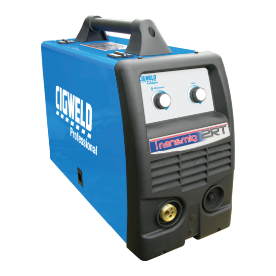
Page 19: 2Rt Wire Feeder Controls, Indicators And Features
INSTALLATION/SETUP TRANSMIG 2RT 3.06 2RT Wire Feeder Controls, 1. Left Knob: WFS (Wire Feed Speed) Control Amperage Control Indicators and Features Wirespeed The 2RT Wirefeeder is designed to be used with the Transmig 250i. Select MIG Process and REMT in the Advanced Features menu on the Transmig 250i to enable Left Knob the controls on the 2RT wirefeeder. - Page 20 TRANSMIG 2RT INSTALLATION/SETUP 3. MIG Torch Adaptor (Euro Style) The MIG Torch adaptor is the connection point for the MIG welding Torch. Connect the MIG Torch by pushing the MIG Torch connector into the brass MIG Torch adaptor firmly and screwing the plastic MIG Torch nut clockwise to secure in position.
-
Page 21: Transmig 250I Power Source Controls, Indicators And Features
INSTALLATION/SETUP TRANSMIG 2RT 3.07 Transmig 250i Power Source Controls, Indicators and Features NOTE: See Transmig 250i Operator Manual for more information. Power Fault Process LIFT TIG STICK Trigger 2T Normal 4T Latch Amps Volts Advanced Left Knob Right Knob Features Arc Control Wirespeed Push For Inductance... - Page 22 TRANSMIG 2RT INSTALLATION/SETUP 5. 2T - 4T Trigger Latch Button CONTINUATION OF 250I POWER SOURCE CONTROLS 1. VRD Indicator 6. Advanced Features Button WARNING When the red VRD indicator is on and welding is being performed, the presence of dangerous Gas Purge.
-
Page 23: Advanced Features Details
INSTALLATION/SETUP TRANSMIG 2RT welding. At times of non-welding, the digital meter will display a pre-set (preview) value of Wirefeed Speed. This value can be adjusted by varying the Left Knob (Control CAUTION No 7). Loose welding terminal connections can cause 10. -
Page 24: Wire Feeder Set Up Mig (Gmaw) Welding With Gas Shielded Mig Wire
TRANSMIG 2RT INSTALLATION/SETUP 3.09 Wire Feeder Set Up MIG (GMAW) Welding with Gas Shielded MIG Wire The Transmig 250i is supplied with a Tweco Fusion 250 AMP air-cooled MIG Torch that can be used with the 2RT Wire Feeder. The Fusion MIG Torch is designed with an ergonomic handle and fewer parts to cause performance problems. The Fusion MIG Torch uses standard readily available Tweco Fusion consumable parts. -
Page 25: Wire Feeder Set-Up For Mig (Fcaw) Welding With Gasless Mig Wire
INSTALLATION/SETUP TRANSMIG 2RT 3.10 Wire Feeder Set-up for MIG (FCAW) Welding with Gasless MIG Wire The Transmig 250i is supplied with a Tweco Fusion 250 AMP air-cooled MIG Torch that can be used with the 2RT Wire Feeder. The Fusion MIG Torch is designed with an ergonomic handle and fewer parts to cause performance problems. The Fusion MIG Torch uses standard readily available Tweco Fusion consumable parts. -
Page 26: Attaching The Tweco Professional Mig Torch (Euro)
TRANSMIG 2RT INSTALLATION/SETUP 3.11 Attaching the Tweco Professional MIG Torch (Euro) 1. Align the pins on the MIG Torch Cable with the pin holes of the MIG Torch receptacle on the front of the system. Press the MIG Torch in and secure by turning the locking ring to the right (clockwise). Refer to Figure 3-8. Attach MIG Torch. -
Page 27: Installing A Handi Spool (200Mm Diameter)
INSTALLATION/SETUP TRANSMIG 2RT 3.12 Installing a Handi Spool (200mm diameter) In order to fit a Handi Spool (200mm diameter) assemble parts in the sequence shown in Figure 3-9. Installation of wire spool. 1. Remove Wire Spool Hub Retaining Clip. Grasp the loop and pull . 2. -
Page 28: Installing A Standard Spool (300Mm Diameter)
TRANSMIG 2RT INSTALLATION/SETUP 3.13 Installing a Standard Spool (300mm diameter) As delivered from the factory, the unit is set for a 15 kg or 300mm spool. Installation of wire spool. Refer to Figure 3-10. 1. Remove Wire Spool Hub Retaining Clip. Grasp the loop and pull . 2. -
Page 29: Inserting Wire Into The Feed Mechanism
INSTALLATION/SETUP TRANSMIG 2RT 3.14 Inserting Wire into the Feed Mechanism WARNING ELECTRIC SHOCK CAN KILL! Make certain the input power is disconnected from the power source before proceeding. Do not reattach the input power until told to do so in these instructions. 1. -
Page 30: Feed Roller Pressure Adjustment
TRANSMIG 2RT INSTALLATION/SETUP 3.15 Feed Roller Pressure Adjustment NOTE Before attempting to set the drive roller pressure you must select GMAW mode on the front panel. See Transmig 250i manual Section 3 for information on how to select this feature. Once selected it will allow the activation of the drive roll when the trigger on the MIG Torch is activated. -
Page 31: Changing The Feed Roll
INSTALLATION/SETUP TRANSMIG 2RT NOTE 3.17 Changing the Feed Roll Installation of all styles of feed rolls for the NOTE Transmig 250i are identical. Feedrolls often come with a rust prohibitive coating that needs to be cleaned off before installation. WARNING A Feedroll consists of two different sized grooves. -
Page 32: Wire Reel Brake
TRANSMIG 2RT INSTALLATION/SETUP Input Guide Lockscrew Output Guide Lockscrew MIG Torch Adapter Lock Bolt Art # A-10346_AB Input Wire Guide Output Wire Guide Figure 3-15: Wire Guide Installation 3.19 Wire Reel Brake The wire reel hub incorporates a friction brake which is adjusted during manufacture for optimum braking. If it is considered necessary, adjustment can be made by turning the tri-lobe nut inside the open end of the wire reel hub. -
Page 33: Shielding Gas Regulator Operating Instructions
INSTALLATION/SETUP TRANSMIG 2RT 4. DO NOT use the regulator as a control valve. When NOTE downstream equipment is not in use for extended Correct adjustment will result in the wire reel periods of time, shut off the gas at the cylinder circumference continuing no further than valve and release the gas from the equipment. - Page 34 TRANSMIG 2RT INSTALLATION/SETUP NOTE All valves downstream of the regulator must be opened to obtain a true flow rate reading on the outlet gauge. (Welding power source must be triggered) Close the valves after the pressure has been set. Installation 1.
- Page 35 INSTALLATION/SETUP TRANSMIG 2RT Adjusting Flow Rate Art: A-05088_AB Figure 3-19: Adjust Flow Rate With the regulator ready for operation, adjust working flow rate as follows: 1. Slowly turn adjusting screw/knob in (clockwise) direction until the outlet gauge indicates the required flow rate.
- Page 36 TRANSMIG 2RT INSTALLATION/SETUP Notes INSTALLATION/SETUP 3-20 Manual 0-5196...
-
Page 37: Section 4: Basic Welding Guide
BASIC WELDING TRANSMIG 2RT SECTION 4: BASIC WELDING Shielding Gas Nozzle (Optional) (Optional) GUIDE Molten Metal Flux Cored Molten Electrode Slag Slag 4.01 MIG (GMAW/FCAW) Basic Welding Solidified Technique Base Metal Weld Metal Two different welding processes are covered in this sec- FCAW Process Art # A-08992_AB tion (GMAW and FCAW), with the intention of providing... - Page 38 TRANSMIG 2RT BASIC WELDING Travel Speed The speed at which the molten pool travels influences the width of the weld and penetration of the welding run. MIG Welding (GMAW) Variables Most of the welding done by all processes is on carbon steel.
- Page 39 BASIC WELDING TRANSMIG 2RT Establishing the Arc and Making Weld Beads Gas Nozzle Before attempting to weld on a finished piece of work, it Contact Tip (Tube) Tip to is recommended that practice welds be made on a sample Electrode Wire Work Distance Actual Stick-out metal of the same material as that of the finished piece.
-
Page 40: Mig (Gmaw/Fcaw) Welding Troubleshooting
TRANSMIG 2RT BASIC WELDING Electrode Wire Size Selection The choice of Electrode wire size and shielding gas used depends on the following • Thickness of the metal to be welded • Type of joint • Capacity of the wire feed unit and Power Source • The amount of penetration required • The deposition rate required • The bead profile desired • The position of welding • Cost of the wire 4.02 MIG (GMAW/FCAW) Welding Troubleshooting Solving Problems Beyond the Welding Terminals The general approach to fix Gas Metal Arc Welding (GMAW) problems is to start at the wire spool then work through to the MIG Torch. - Page 41 BASIC WELDING TRANSMIG 2RT Problem 2 - Inconsistent Wire Feed WARNING Disengage the feed roll when testing for gas flow by ear. Wire feeding problems can be reduced by checking the following points. FAULT CAUSE 1 Feed roller driven by motor in the Wire spool brake is too tight.
- Page 42 B Low primary voltage B Contact supply authority. C Fault in power source C Have an Accredited CIGWELD Service Provider test then replace the faulty component. 8 Arc does not have The Wirefeeder has been Connect the Wirefeeder to the positive (+) welding...
-
Page 43: Section 5: Routine Service Requirements
Replace all exterior broken parts of wirefeeder 6 Months Bring the unit to an authorized CIGWELD Service Provider to remove any accumulated dirt and dust from the interior. This may need to be done more frequently under exceptionally dirty conditions. -
Page 44: Cleaning The Feed Rolls
TRANSMIG 2RT PROBLEMS/SERVICE 5.02 Cleaning the Feed Rolls Clean the grooves in the drive rolls frequently. This can be done by using a small wire brush. Also wipe off, or clean the grooves on the upper feed roll. After cleaning, tighten the feed roll retaining knobs. CAUTION Do not use compressed air to clean the Welding Power Source. -
Page 45: Section 6: Key Spare Parts
REPLACEMENT PARTS TRANSMIG 2RT SECTION 6: KEY SPARE PARTS 6.01 2RT WIRE FEEDER REPLACEMENT PARTS Figure 6-1 TRANSMIG 2RT SPARE PARTS (LEFT SIDE) ITEM PART NUMBER DESCRIPTION W7005311 Spool Hub Assembly W7005353 Wire Drive Assembly, (Does not include motor or feed rolls) W6000900 Guide, Inlet 0.6-1.6mm See Appendix 1... - Page 46 TRANSMIG 2RT REPLACEMENT PARTS Notes REPLACEMENT PARTS Manual 0-5196...
-
Page 47: Appendix 1: Options And Accessories
APPENDIX TRANSMIG 2RT APPENDIX 1: OPTIONS AND ACCESSORIES Description Part Number Tweco Professional Fusion 250 MIG Torch, 3.6 metre Euro OTWF212X3035 Tweco 4, 400A MIG torch, 3.6 metre Euro OTWX412/3545 Table A-1: Options and Accessories FLUX FLUX HARD SOFT CORED CORED (0.6 to 1.0) (0.8,0.9,1.0) -
Page 48: Appendix 2: 2Rt Wiring Schematic
TRANSMIG 2RT APPENDIX APPENDIX 2: 2RT WIRING SCHEMATIC Figure A-2: 2RT Wiring Schematic APPENDIX Manual 0-5196... -
Page 50: Cigweld Limited Warranty
CIGWELD’s sole option, of any components or parts of the product determined by CIGWELD to be defective. -
Page 51: Terms Of Warranty - April 2010
CIGWELD. 4. CIGWELD declares that, to the extent permitted by law, it hereby limits its liability in respect of the supply of goods which are not of a kind ordinarily acquired for personal, domestic or household use or consumption to any one or more of the following (the choice of which shall be at the option of CIGWELD). -
Page 52: Warranty Schedule - April 2010
Accredited Distributor of the equipment. Notwithstanding the foregoing, in no event shall the warranty period extend more than the time stated plus one year from the date CIGWELD delivered the product to the Ac- credited Distributor. Unless otherwise stated the warranty period includes parts and labour. CIGWELD reserves the right to request documented evidence of date of purchase. -
Page 53: Global Customer Service Contact Information
GLOBAL CUSTOMER SERVICE CONTACT INFORMATION Cigweld, Australia Thermadyne, China 71 Gower Street RM 102A Preston, Victoria 685 Ding Xi Rd Chang Ning District Australia, 3072 Shanghai, PR, 200052 Telephone: 61-3-9474-7400 Telephone: 86-21-69171135 Fax: 61-3-9474-7391 Fax: 86-21-69171139 Email: cigweldsales@cigweld.com.au Thermadyne Asia Sdn Bhd... - Page 54 Printed in: U.S.A. Asia Pacific Regional Headquarters 71 Gower Street Preston, Victoria, Australia, 3072 Telephone: +61 3 9474 7400 FAX: +61 3 9474 7391 Email: enquiries@thermadyne.com.au www.thermadyne.com...
Need help?
Do you have a question about the 2RT TRANSMIG and is the answer not in the manual?
Questions and answers