Table of Contents
Advertisement
Operating Manual
T
RANSMIG
T
RANSMIG
2R T
RANSMIG
T
RANSMIG
T
RANSMIG
2R T
RANSMIG
MIGTRN0001 Issue 2 14/09/98
210 Compact Power Source
Remote Power Source
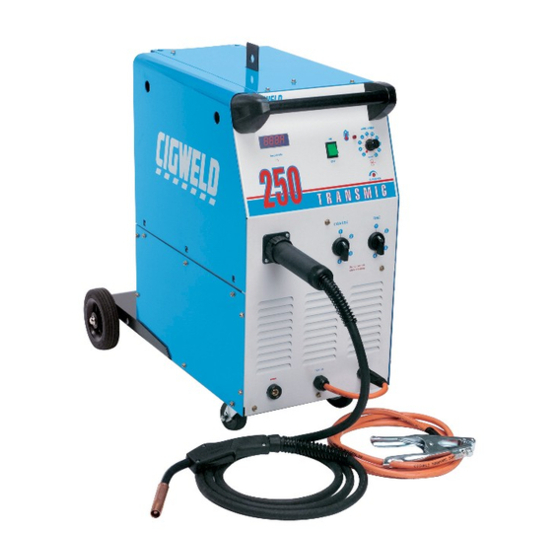
250 Compact Power Source
Remote Power Source
210/250 Wirefeeder
310 Compact Power Source
330 Remote Power Source
330 Wirefeeder
704832
704808
704833
704809
704975
704836
705085
704841
Advertisement
Table of Contents


Need help?
Do you have a question about the Transmig 210 and is the answer not in the manual?
Questions and answers