Table of Contents
Advertisement
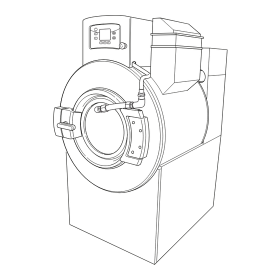
Washer-Extractors
Keep These Instructions for Future Reference.
(If this machine changes ownership, this manual must accompany machine.)
Pocket Hardmount
UniLinc and M30 Control
Refer to Page 6 for Model Numbers
45 AND 65 MODELS
45 AND 65 MODELS
www.alliancelaundry.com
PHM847N
PHM847N
UniLinc
PHM848N
PHM848N
M30
Part No. F8410701ENR3
November 2012
Advertisement
Table of Contents

Subscribe to Our Youtube Channel
Related Manuals for Alliance Laundry Systems UWN045K2M


Summary of Contents for Alliance Laundry Systems UWN045K2M
- Page 1 Washer-Extractors Pocket Hardmount UniLinc and M30 Control Refer to Page 6 for Model Numbers PHM847N PHM847N UniLinc 45 AND 65 MODELS PHM848N PHM848N 45 AND 65 MODELS Keep These Instructions for Future Reference. (If this machine changes ownership, this manual must accompany machine.) Part No.
-
Page 3: Table Of Contents
All rights reserved. No part of the contents of this book may be reproduced or transmitted in any form or by any means without the expressed written consent of the publisher. F8410701 (EN) © Copyright, Alliance Laundry Systems LLC – DO NOT COPY or TRANSMIT... - Page 4 Beginning of Day ................47 End of Day ..................47 Weekly....................47 Monthly....................48 Quarterly ....................49 Care of Stainless Steel ................50 Disposal of Unit ................... 51 © Copyright, Alliance Laundry Systems LLC – DO NOT COPY or TRANSMIT F8410701 (EN)
-
Page 5: Safety Information
6. To reduce the risk of an electric shock or fire, DO NOT use an extension cord or an adapter to connect the washer to the electrical power source. © Copyright, Alliance Laundry Systems LLC – DO NOT COPY or TRANSMIT F8410701 (EN) - Page 6 The air gap must be maintained. 17. Do not operate the machine without the water reuse plug or water reuse system in place, if applicable. © Copyright, Alliance Laundry Systems LLC – DO NOT COPY or TRANSMIT F8410701 (EN)
-
Page 7: Safety Decals
Do not bypass any safety devices in the machine. safety hazards. WARNING Operating the machine with severe out-of- balance loads could result in personal injury and serious equipment damage. W728 © Copyright, Alliance Laundry Systems LLC – DO NOT COPY or TRANSMIT F8410701 (EN) -
Page 8: Introduction
UWL065K1L UWN065K2M UWU065K2L UWL065K1M UWN065T3L UWU065K2M UWL065K2L UWN065T3M UWU065T3L UWL065K2M UWN065T3V UWU065T3M UWL065T3V UWN065T4L UWU065T3V UWL065T4V UWN065T4M UWU065T4L UWN045K1L UWN065T4V UWU065T4M UWN045K1M UWU045K1L UWU065T4V UWN045K2L UWU045K1M © Copyright, Alliance Laundry Systems LLC – DO NOT COPY or TRANSMIT F8410701 (EN) -
Page 9: Delivery Inspection
2. Press the keypad until Diagnostic is highlighted. 3. Press the keypad. 4. Press the keypad until machine ID is highlighted. 5. Press the keypad. © Copyright, Alliance Laundry Systems LLC – DO NOT COPY or TRANSMIT F8410701 (EN) -
Page 10: Specifications And Dimensions
28.09 (713) 28.09 (713) Drive Train Information Number of motors in. drive train Drive motor power, hp (kW) 5.0 (3.7) 5.0 (3.7) (Variable-speed models) (Variable-speed models) © Copyright, Alliance Laundry Systems LLC – DO NOT COPY or TRANSMIT F8410701 (EN) - Page 11 2.4 (3.7) raise bath temperature, 10°F, min (5°C, min) 1.9 (2.8) 2.7 (4.1) HIGH 2.1 (3.2) 3.0 (4.6) Max Extract Noise Emission, dB Med Extract Agitate © Copyright, Alliance Laundry Systems LLC – DO NOT COPY or TRANSMIT F8410701 (EN)
- Page 12 PRIMARY FILL CONNECTIONS .875 CHEM SUPPLY ELECTRICAL 1.125 CHEM SUPPLY ELECTRICAL 1.125 ELECTRICAL 1.500 ELECTRICAL STEAM CONNECTION BACK PHM867N 45 – 65 MODELS PHM867N Figure 1 © Copyright, Alliance Laundry Systems LLC – DO NOT COPY or TRANSMIT F8410701 (EN)
-
Page 13: Machine Dimensions
28.94 in. (735 mm) 28.09 in. (713 mm) 28.09 in. (713 mm) 20.88 in. (530 mm) 20.88 in. (530 mm) 30.77 in. (782 mm) 30.77 in. (782 mm) © Copyright, Alliance Laundry Systems LLC – DO NOT COPY or TRANSMIT F8410701 (EN) -
Page 14: Mounting Bolt Hole Location
“B”. Refer to Table 2. FRONT OF MACHINE (45) FRONT OF MACHINE (65) PHM817N Figure 2 © Copyright, Alliance Laundry Systems LLC – DO NOT COPY or TRANSMIT F8410701 (EN) - Page 15 41.41 in. (1051 mm) 41.41 in. (1051 mm) 30.08 in. (764 mm) 30.08 in. (764 mm) Inside 36.4 in. (924 mm) 36.4 in. (924 mm) Table 2 © Copyright, Alliance Laundry Systems LLC – DO NOT COPY or TRANSMIT F8410701 (EN)
-
Page 16: Floor Layout
20 in. minimum (508 mm) 20 in. minimum (508 mm) A (Distance to wall) 6 in. minimum (153 mm) 6 in. minimum (153 mm) * Minimum adjacent unit spacing © Copyright, Alliance Laundry Systems LLC – DO NOT COPY or TRANSMIT F8410701 (EN) - Page 17 20 in. minimum (508 mm) A (Distance to Back edge of machine 2) 12 in. minimum (305 mm) 12 in. minimum (305 mm) * Minimum adjacent unit spacing © Copyright, Alliance Laundry Systems LLC – DO NOT COPY or TRANSMIT F8410701 (EN)
-
Page 18: Single Machine Foundation Requirements
For alternate installation specifications based on your soil type, location, building structure, unique floor geometry, machine types, and utilities consult a structural engineer in your local area. © Copyright, Alliance Laundry Systems LLC – DO NOT COPY or TRANSMIT F8410701 (EN) -
Page 19: Machine Foundation And Pad Installation
*For smaller areas for installations, a recommended minimum pad size of 50 in. (1270 mm) x 50 in. (1270 mm) with a thickness of 18 in. (457 mm) is an option. © Copyright, Alliance Laundry Systems LLC – DO NOT COPY or TRANSMIT F8410701 (EN) - Page 20 14. Proceed to Machine Mounting and Grouting section. 13. Using a mounting bolt template or machine base, mark where the holes should be drilled to mount the machine. © Copyright, Alliance Laundry Systems LLC – DO NOT COPY or TRANSMIT F8410701 (EN)
-
Page 21: Machine Installation - L-Speed And 45 Pound
(305 mm) 2.5 in. 12 in. (64 mm) (305 mm) PHM873N Existing Floor Perimeter Reinforcing Bar 3500 PSI (minimum) Concrete Compacted Fill Reinforcing Bar Figure 7 © Copyright, Alliance Laundry Systems LLC – DO NOT COPY or TRANSMIT F8410701 (EN) -
Page 22: M-Speed Models
(64 mm) 14 in. (356 mm) 8 in. (203 mm) PHM853N Existing Floor Perimeter Reinforcing Bar 3500 PSI (minimum) Concrete Compacted Fill Reinforcing Bar Figure 10 © Copyright, Alliance Laundry Systems LLC – DO NOT COPY or TRANSMIT F8410701 (EN) -
Page 23: Machine Installation - V-Speed Models
(64 mm) 18 in. (457 mm) 12 in. (305 mm) PHM853N Existing Floor Perimeter Reinforcing Bar 3500 PSI (minimum) Concrete Compacted Fill Reinforcing Bar Figure 13 © Copyright, Alliance Laundry Systems LLC – DO NOT COPY or TRANSMIT F8410701 (EN) -
Page 24: Machine Mounting And Grouting
6. Ensure all air pockets are removed from adhesive surrounding the bolt. 7. Allow adhesive around bolt to cure completely. IMPORTANT: Refer to bolt manufacturer’s recommended adhesive cure times. © Copyright, Alliance Laundry Systems LLC – DO NOT COPY or TRANSMIT F8410701 (EN) - Page 25 IMPORTANT: Refer to recommended grout cure times from manufacturer before torquing locknuts. NOTE: Check and retighten the locknuts after five to ten days of operation and every month thereafter. © Copyright, Alliance Laundry Systems LLC – DO NOT COPY or TRANSMIT F8410701 (EN)
-
Page 26: Floor Load Data
Maximum vertical load, lb (kN) 3810 (16.9) 3890 (17.3) Maximum base moment, lb-ft. (kN-m) 8480 (37.7) 8480 (37.7) Acting in the downward direction against the floor. Table 4 © Copyright, Alliance Laundry Systems LLC – DO NOT COPY or TRANSMIT F8410701 (EN) -
Page 27: Drain Connection Requirements
Increasing the drain hose length, installing elbows, or require proportionately larger drain connections. causing bends will decrease drain flow rate and Refer to Table 6. increase drain times, impairing machine performance. © Copyright, Alliance Laundry Systems LLC – DO NOT COPY or TRANSMIT F8410701 (EN) - Page 28 Table 5 Drain Line Sizing Minimum Drain I.D., in. (mm) Number of Machines Model 3 (76) 4 (102) 6 (152) 6 (152) 45 - 65 Table 6 © Copyright, Alliance Laundry Systems LLC – DO NOT COPY or TRANSMIT F8410701 (EN)
-
Page 29: Water Connection
If additional hose lengths are needed or using hoses other than those supplied by manufacturer, flexible hoses with screen filters are required. Lower pressures will increase fill times. © Copyright, Alliance Laundry Systems LLC – DO NOT COPY or TRANSMIT F8410701 (EN) -
Page 30: Electrical Installation Requirements
Verify that a ground wire from a proven earth ground is connected to the lug near the input power block on this machine. W360 © Copyright, Alliance Laundry Systems LLC – DO NOT COPY or TRANSMIT F8410701 (EN) - Page 31 Refer to Figure 20 and 21. MACHINES WITHOUT ELECTRIC HEAT PHM721N Grounding Lug: Connect to proven earth ground Customer Input Power Terminals Figure 21 © Copyright, Alliance Laundry Systems LLC – DO NOT COPY or TRANSMIT F8410701 (EN)
-
Page 32: Non-Ce Models
Contact your local Authority having jurisdiction if you have questions. Circuit breakers should be UL 489 listed or better. Single phase circuit breakers for single phase machines only; three phase circuit breakers for all others. Table 9 © Copyright, Alliance Laundry Systems LLC – DO NOT COPY or TRANSMIT F8410701 (EN) - Page 33 Contact your local Authority having jurisdiction if you have questions. Circuit breakers should be UL 489 listed or better. Single phase circuit breakers for single phase machines only; three phase circuit breakers for all others. Table 10 © Copyright, Alliance Laundry Systems LLC – DO NOT COPY or TRANSMIT F8410701 (EN)
-
Page 34: Ce Models
Contact your local Authority having jurisdiction if you have questions. Circuit breakers should be UL 489 listed or better. Single phase circuit breakers for single phase machines only; three phase circuit breakers for all others. Table 11 © Copyright, Alliance Laundry Systems LLC – DO NOT COPY or TRANSMIT F8410701 (EN) - Page 35 Contact your local Authority having jurisdiction if you have questions. Circuit breakers should be UL 489 listed or better. Single phase circuit breakers for single phase machines only; three phase circuit breakers for all others. Table 12 © Copyright, Alliance Laundry Systems LLC – DO NOT COPY or TRANSMIT F8410701 (EN)
-
Page 36: Steam Requirements (Steam Heat Option Only)
Steam inlet connection, in. (mm) 1/2 (DN13) Number of steam inlets Recommended pressure, psi (bar) 30 - 85 (2.0 - 5.9) Maximum pressure, psi (bar) 85 (5.9) Table 13 © Copyright, Alliance Laundry Systems LLC – DO NOT COPY or TRANSMIT F8410701 (EN) -
Page 37: Chemical Injection Supply System
CAUTION Drill out plugs and nipples before making supply hose connection. Failure to do so can cause buildup of pressure and risk a tubing rupture. W491 © Copyright, Alliance Laundry Systems LLC – DO NOT COPY or TRANSMIT F8410701 (EN) - Page 38 Do not attempt to make chemical injection electrical connections to points other than those provided specifically for that purpose by the factory. © Copyright, Alliance Laundry Systems LLC – DO NOT COPY or TRANSMIT F8410701 (EN)
-
Page 39: External Supplies
PHM821N External Supply Power Output Red Jumper Wire Internal Control Transformer 24VAC Terminal RELAY COM Terminal 24VAC COM Terminal External Dispenser Input Signal Common Figure 24 © Copyright, Alliance Laundry Systems LLC – DO NOT COPY or TRANSMIT F8410701 (EN) -
Page 40: Chemical Injection Using External Ac Power Source
Optional External Supply Wiring Diagram. W699 © Copyright, Alliance Laundry Systems LLC – DO NOT COPY or TRANSMIT F8410701 (EN) -
Page 41: External Supply Signals
Supply Connection or Figure 27 for External AC equipment. Connection. = Neutral = Power PHM822N ES1 Power supply Supply 1 Signal K1 Contact Figure 26 © Copyright, Alliance Laundry Systems LLC – DO NOT COPY or TRANSMIT F8410701 (EN) - Page 42 Specifications and Dimensions = Neutral = Power PHM824N ES1 Power supply Supply 1 Signal K1 Contact Figure 27 © Copyright, Alliance Laundry Systems LLC – DO NOT COPY or TRANSMIT F8410701 (EN)
-
Page 43: Operation
6. Press keypads to select desired wash cycle. 7. Press to start the selected cycle. © Copyright, Alliance Laundry Systems LLC – DO NOT COPY or TRANSMIT F8410701 (EN) -
Page 44: Shakeout Routine
Rapid Advance to a drain step that occurs before an extract or spray rinse extract step. © Copyright, Alliance Laundry Systems LLC – DO NOT COPY or TRANSMIT F8410701 (EN) -
Page 45: Operating Instructions For M30 Control
NOTE: Supply dispenser compartment cups must not be removed when an external chemical injection supply system is attached to the machine. © Copyright, Alliance Laundry Systems LLC – DO NOT COPY or TRANSMIT F8410701 (EN) -
Page 46: Shakeout Routine
Custom #7 The shakeout time is set at the factory to agitate for 32 Custom #8 seconds. Custom #9 Custom #10 Custom #11 Custom #12 Table 14 © Copyright, Alliance Laundry Systems LLC – DO NOT COPY or TRANSMIT F8410701 (EN) -
Page 47: Start Up
If switch is tripped, check if machine is level and then for poor grouting and broken anchor bolts. DO NOT BYPASS SAFETY SWITCH. Contact a qualified service technician for further assistance. © Copyright, Alliance Laundry Systems LLC – DO NOT COPY or TRANSMIT F8410701 (EN) -
Page 48: Maintenance
The list is broken up into infected garments. “DAILY”, “WEEKLY”, “MONTHLY” and “QUARTERLY”. The following maintenance procedures must be performed regularly at the required intervals. © Copyright, Alliance Laundry Systems LLC – DO NOT COPY or TRANSMIT F8410701 (EN) -
Page 49: Daily
5. Verify that insulation is intact on all external wires and that all connections are secure. If bare wire is evident, call a service technician. © Copyright, Alliance Laundry Systems LLC – DO NOT COPY or TRANSMIT F8410701 (EN) -
Page 50: Monthly
58 Hz (± 2 Hz) is obtained mid-span. Tighten jam nut to PHM865N spring bracket. Refer to Figure 37. Deflection Span Length Figure 38 © Copyright, Alliance Laundry Systems LLC – DO NOT COPY or TRANSMIT F8410701 (EN) -
Page 51: Quarterly
11. Remove chemical supply components (where applicable) and check for residual chemicals. Clean or replace as necessary. © Copyright, Alliance Laundry Systems LLC – DO NOT COPY or TRANSMIT F8410701 (EN) -
Page 52: Care Of Stainless Steel
• Remove discoloration or heat tint from overheating by scouring with a powder or by employing special chemical solutions. © Copyright, Alliance Laundry Systems LLC – DO NOT COPY or TRANSMIT F8410701 (EN) -
Page 53: Disposal Of Unit
MIX1N purchased. Figure 39 © Copyright, Alliance Laundry Systems LLC – DO NOT COPY or TRANSMIT F8410701 (EN)
Need help?
Do you have a question about the UWN045K2M and is the answer not in the manual?
Questions and answers
Height from floor to
The height from the floor to the top of the Alliance Laundry Systems UWN045K2M is 41.41 inches (1051 mm).
This answer is automatically generated