Table of Contents
Advertisement
INSTALLATION
AND PROGRAMMING
MANUAL
Intelligent Interactive Analogue Addressable
Fire Alarm Control Panel
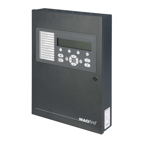
MAGPRO16
Attention:
This manual contains information on limitations regarding product use and
function and information on the limitations as to liability of the manufacturer.
The entire manual should be carefully read.
The information in this manual is a subject to change without notice!
Advertisement
Table of Contents

Related Manuals for ESP MAGPRO16


Summary of Contents for ESP MAGPRO16
- Page 1 AND PROGRAMMING MANUAL Intelligent Interactive Analogue Addressable Fire Alarm Control Panel MAGPRO16 Attention: This manual contains information on limitations regarding product use and function and information on the limitations as to liability of the manufacturer. The entire manual should be carefully read.
-
Page 2: Table Of Contents
MAGPRO16 Addressable Fire Alarm Panel – Installation and Programming Manual Table of Contents 1. INTRODUCTION ................................5 1.1. General Description............................5 1.2. General Specifications ..........................5 1.2.1 General Technical Specifications ....................5 1.2.2 Possible Hardware Configurations ....................6 1.2.3 Environment ............................. 6 1.2.4 Electrical Characteristics ......................... - Page 3 MAGPRO16 Addressable Fire Alarm Panel – Installation and Programming Manual 7.2.5 Zone Name ............................ 29 7.2.6 Zone Operation Modes ........................29 7.2.7 Programming Delays Т2 ........................ 30 7.2.8 Arranging Zones in Groups ......................31 7.3. Devices Setup Menus ..........................31 7.3.1 Submenus for General Setting ......................
- Page 4 MAGPRO16 Addressable Fire Alarm Panel – Installation and Programming Manual STANDARDS AND CONFORMITY The addressable fire alarm control panel MAGPRO16 is designed and certified according and with conformity to EN 54 – 2/4 standard. Conforms and approved in accordance with CPR (Construction Products Regulation).
-
Page 5: Introduction
MAGPRO16 Addressable Fire Alarm Panel – Installation and Programming Manual 1. INTRODUCTION 1.1. General Description MAGPRO16 is an addressable fire panel with maximum coverage of 16 zones and connecting and up to 2 loops. The panel supports communication protocol MAGPRO (MAGPRO16-L250 Loop) and operation with MAGPRO addressable device series. -
Page 6: Possible Hardware Configurations
MAGPRO16 Addressable Fire Alarm Panel – Installation and Programming Manual 16 groups for zones’ organization 5 monitored potential outputs: SND1 (Sounder 1) SND2 (Sounder 2) FIRE FAULT (In case of Fault event the output is deactivated.) EXT (Extinguishing/ Fire Protection – An output for sending an fire alarm signal to automatic fire extinguishing system) ... - Page 7 MAGPRO16 Addressable Fire Alarm Panel – Installation and Programming Manual Main power supply In normal operating conditions, the fire panel is powered from the mains voltage line. In case of mains voltage line loss the fire panel is equipped with one rechargeable battery. The characteristics of the main power supply are as follows: ...
-
Page 8: Installation
MAGPRO16 Addressable Fire Alarm Panel – Installation and Programming Manual 2. INSTALLATION 2.1. Wall Mounting • The panel must be installed in a clean dry place and must not be subjected to impact or vibrations (Figure 1). It must be situated far from heating appliances. The temperature must be within -5ºС and + 50ºC. The fire panel is not waterproof! •... -
Page 9: System Components
MAGPRO16 Addressable Fire Alarm Panel – Installation and Programming Manual • Use the template in the set to fix the mounting holes of the metal box on the wall. • Drill holes (suitable for anchors Ø6mm) on the wall and fix the metal box. - Page 10 3 – Description of the LCD-module The MAGPRO16 fire alarm addressable panel is equipped with letter-digit LCD-module (4 rows x 40 symbols). The user can enter device and zone names using the navigation and control buttons. The display has an adjustable backlight with 20 levels of intensity.
-
Page 11: Configuration Of The Basic Modules
5 – Place for accumulator battery, 1 х 12V/ 18Ah 6 – Place for mounting of AJAX LAN communication module 7 – Place for mounting of redundant network module 2.2.3 Description of the main PCB (control panel) Figure 7 – Main PCB of the MAGPRO16 fire alarm panel... - Page 12 LOOP 1 (-LOOP+ / +ERT / -LOOP+) – Terminal row for connecting Loop 1 in the system. LOOP 2 – Interface connector for adding MAGPRO16-L250 loop (for Loop 2) in the system configuration. INDICATION – Interface connection for the indication module.
-
Page 13: Connection Of Signaling Devices
Figure 11 – Example for connecting of end device (an illuminated exit sign) to the Monitored FIRE Output. 2.3.3 Connecting to the Specialized Inputs The specialized inputs of MAGPRO16 fire alarm panel are designed for operation with an extinguishing control panel. The example connection diagrams are presented on Figures 12 а) and b). -
Page 14: Loop Controller
Detector N Figure 13 – Connecting of detectors to a loop controller In the configuration of addressable fire alarm panel MAGPRO16 could be mounted a second loop controller as a separate module – see Figure 14. ATTENTION! Do not add or remove loop expanders to the fire panel configuration when... -
Page 15: Maximum Permissible Cable Length
The maximum length of the loop in the system could vary according to the cross-section and the ohmic resistance of the used cable. ATTENTION! MAGPRO16-L250 Loop controller supports up to 250 devices, regardless of the type! To ensure the correct operation of the system is necessary to make some calculations in advance: 1. -
Page 16: Connecting To The Main Power Source
2.4. Connecting to the Main Power Source The mains power supply of MAGPRO16 fire alarm panel is realized with connection of the main power cable to the 230V terminal, mounted in the metal box under the powers source. The connection between the 230V terminal and the main power source is done from the manufacturer. -
Page 17: Connecting A Heat Printer
Figure 19 2.8. Connecting an AJAX LAN Communication Module The addressable fire alarm panel MAGPRO16 is designed for monitoring via serial interface connection using specialized AJAX communication module. The monitoring could be realized over LAN network, according the type of the used module. -
Page 18: Programming Types
To program the fire alarm panel MAGPRO16 you should first to install the MAGPRO programming software on your computer. To program the MAGPRO16 panel you have to use cable type USB Micro B - USB A – Figure 20. MAGPRO... -
Page 19: Firmware Update From Usb Drive
MAGPRO16 folder. 4. FULL HARDWARE RESET The full hardware reset of MAGPRO16 addressable fire alarm panel allows the engineer to restore all factory settings and access code combinations for level 2 (Maintenance) and 3 (Installer). To perform full hardware reset, follow the steps: 1. -
Page 20: Programming Of Magpro16 Fire Alarm Panel
5.2. Codes and Access Levels There are three access levels in MAGPRO16 panel: User, Maintenance and Installer. Every level comprises different functions and operations. To enter Maintenance and Installer levels is necessary to enter valid access code:... - Page 21 MAGPRO16 Addressable Fire Alarm Panel – Installation and Programming Manual The access codes could be changed only from level Installer - menu 6) General Settings - submenu 6.1) Access codes. There are different restrictions on the panel functions in the relative access levels, which are shown in the table below:...
-
Page 22: Description Of The Operation Modes
6. DESCRIPTION OF THE OPERATION MODES In this section you can find detailed descriptions of all operation modes of MAGPRO16 addressable fire alarm panel. The modes for reviewing of system events are accessible only from level 1 without entering access code. If no alarm, fault or warning messages, active tests and disablements are present, then the panel is in normal operation mode and only the current day and time are displayed. -
Page 23: Review Of Disablements
MAGPRO16 Addressable Fire Alarm Panel – Installation and Programming Manual 6.3. Review of Disablements The messages for disablements are displayed with normal priority. If no alarm or fault events are present, and there are active disablements in the system, the DISABLEMENTS mode is blinking together with the number of the first disablement. -
Page 24: Review Of Warning Messages
MAGPRO16 Addressable Fire Alarm Panel – Installation and Programming Manual After choosing the button (2) TESTS the screen displays: To exit the review of running tests mode, press CANCEL button. 6.5. Review of Warning Messages The messages for warnings are displayed with low priority. If no alarm or fault events or disablements and tests are present, and there are active warnings in the system, the WARNINGS mode is blinking together with the number of the first message. -
Page 25: Silencing The Internal Buzzer
MAGPRO16 Addressable Fire Alarm Panel – Installation and Programming Manual 6.6. Silencing the Internal Buzzer The internal buzzer of addressable fire alarm panel MAGPRO16 is signaling in case of activated alarm or fault events in the system. The buzzer silencing is available from every access level without code entry. -
Page 26: Description Of The Programming Menus
MAGPRO16 Addressable Fire Alarm Panel – Installation and Programming Manual 7. DESCRIPTION OF THE PROGRAMMING MENUS The programming menus are accessible from level 2 (Maintenance) and level 3 (Installer) after entering a valid access code. In level 2 could be realized partial programming of parameters, and some values are accessible only for reviewing. -
Page 27: Review Of List Of Events By Date
MAGPRO16 Addressable Fire Alarm Panel – Installation and Programming Manual 7.1.2 Review of List of Events by Date From the main screen of VIEW LOG menu press (2) FROM button. In “FROM” submenu the installer can extract a list of events by date. Set in sequence the day, the month and the last two digits of the year. The edited digit is flashing. -
Page 28: Zones Menu
MAGPRO16 Addressable Fire Alarm Panel – Installation and Programming Manual 7.2. Zones Menu This menu allows the installer to review and change the status of every zone. In the ‘ZONES’ menus the installer can test and enable/ disable the zones. Up to 16 zone numbers are available for settings. The currently edited zone number is blinking. -
Page 29: Disabling Zones
MAGPRO16 Addressable Fire Alarm Panel – Installation and Programming Manual 7.2.3 Disabling Zones From the main screen of ZONES menu, select a zone number using the up and down arrow buttons and press button (4) DISABLE. The zone status is changed to DISABLED – the panel stops following the status of the connected devices to the zone and will not alert for alarms and faults from them. -
Page 30: Programming Delays Т2
MAGPRO16 Addressable Fire Alarm Panel – Installation and Programming Manual Examples for 2 DEVICES action mode operation: EXAMPLE 1 EXAMPLE 2 5 min 5 min Time Time 1 – An incoming alarm signal from Detector 1 and zone reset; 2 – Awaiting for a second alarm signal from other detector in the zone – Pre Alarm Mode;... -
Page 31: Arranging Zones In Groups
This menu allows the installer to review and change the status of every device. Up to 250 devices per loop are available for settings (up to 500 when using second loop in the MAGPRO16 panel). In the ‘DEVICES SETUP’ menus the installer can save new devices found in the system, to remove or disable them. -
Page 32: Saving The New Found Devices
MAGPRO16 Addressable Fire Alarm Panel – Installation and Programming Manual 7.3.2 Saving the New Found Devices The MAGPRO16-L250 loop controller automatically recognizes the types of devices in the loop. In case of finding new devices in the system configuration (Loop 1 and Loop2) the panel displays the message “... -
Page 33: Programming Of Device Parameters
Attention: Programming device type parameters is available only from access level 3! The MAGPRO16 fire alarm addressable panel operates with full range of MAGPRO addressable detectors, call points, sounders and modules via MAGPRO communication protocol. According the type of the device, the setting parameters are different. - Page 34 MAGPRO16 Addressable Fire Alarm Panel – Installation and Programming Manual (3) TEST – Press the button to enter in a new screen for checking of the following current parameters: - T fire – Shows the operating temperature of the detector, in degrees centigrade.
- Page 35 MAGPRO16 Addressable Fire Alarm Panel – Installation and Programming Manual MAGPRO-DBS – Base with sounder Use the functional buttons to set the following parameters: (1) SOUND LEVEL – Every pressing of the button alternatively changes the sound level between HIGH/ LOW – as this depends on the number of the connected sounders to the loop: - HIGH –...
- Page 36 MAGPRO16 Addressable Fire Alarm Panel – Installation and Programming Manual MAGPRO-Mini – Mini input module The MAGPRO-Mini is a compact module with one input. The module monitors and transfers to control panel the state of this input - state ON or state OFF. MAGPRO-Mini is designed for built-in installation in the mounting box of the device.
- Page 37 MAGPRO16 Addressable Fire Alarm Panel – Installation and Programming Manual FIRE ZONE GROUP - Activation from a zone in fire alarm included in a group. Set a group number. FIRE (common) - Activation in case of fire alarm event in the system.
- Page 38 MAGPRO16 Addressable Fire Alarm Panel – Installation and Programming Manual MAGPRO-R – Module for 240V interface Relay module with interface for 240 VAC. The module is available in two versions with 1 and 2 relay outputs. Use the functional buttons to set the following parameters: (1) OUT 1 –...
-
Page 39: Addressing Menus
MAGPRO16 Addressable Fire Alarm Panel – Installation and Programming Manual 7.4. Addressing Menus Attention: The addressing menus are available only from access level 3! This menu allows the installer to set or change the device address or to perform self-addressing procedure. The type of addressing depends on the installer’s preferences and the system capacity and configuration. -
Page 40: Self-Addressing
MAGPRO16 Addressable Fire Alarm Panel – Installation and Programming Manual Use the button ‘CHANGE’ to switch to loop 2 if present in the system. Press the right arrow button to switch to ‘NEW ADDRESS’ field. Press right arrow button to move to field ‘NEW ADDRESS. -
Page 41: Panel Outputs Menus
MAGPRO16 Addressable Fire Alarm Panel – Installation and Programming Manual 7.5. Panel Outputs Menus This menu allows the installer to disable/ enable and to set time delay for some of the outputs of the control panel: - Sounder Outputs (SND 1, SND 2) -
Page 42: Fire Output
MAGPRO16 Addressable Fire Alarm Panel – Installation and Programming Manual 7.5.3 Fire Output In this submenu the installer can disable/ enable the fire output activation and the time delay operation. To access the FIRE submenu, enter in the installer’s menu - 5. PANEL OUTPUTS - FIRE (3). -
Page 43: General Settings Menu
MAGPRO16 Addressable Fire Alarm Panel – Installation and Programming Manual 7.6. General Settings Menu This menu allows the installer to make some common settings for the fire panel. The menu is accessible from access levels 2 and 3, as for the level to are introduced some restrictions. -
Page 44: Setting The Date And Time
IMPORTANT NOTES! The MAGPRO16 panel is equipped with built-in battery for saving the set time and date in case of main or back-up power supply lost. Put a jumper on JP7 terminals on the control panel PCB to enable the built-in battery and saving the set time and date. -
Page 45: Panel General Settings
MAGPRO16 Addressable Fire Alarm Panel – Installation and Programming Manual 7.6.4 Panel General Settings In this submenu the installer can make some adjustments for the panel performance. To access the PANEL SETTINGS submenu, enter in the installer’s menu - 6. GENERAL SETTING - 6.4) PANEL SETTINGS. -
Page 46: Save Configuration Menu
MAGPRO16 Addressable Fire Alarm Panel – Installation and Programming Manual 7.7. Save Configuration Menu Attention: Saving the system configuration is available only from access level 3! In this menu the installer performs saving of the new found devices in the system configuration. The panel will ask for confirmation of the action. -
Page 47: Network
MAGPRO16 Addressable Fire Alarm Panel – Installation and Programming Manual 7.10. Network In this menu the installer can make the settings for the redundant network between fire panels. 7.10.1 Network Settings To access the NETWORK settings, enter in the installer’s menu - 10. NETWORK – 10.1) SETTINGS. The screen... -
Page 48: Active Isolators Menu
MAGPRO16 Addressable Fire Alarm Panel – Installation and Programming Manual 7.11. Active Isolators Menu This is an information menu for reviewing the active isolators (built-in isolator in MAGPRO devices). The active isolators in the system are displayed as device addresses in the fields “L1” and “L2” for MAGPRO loops. -
Page 49: Appendix А
MAGPRO16 Addressable Fire Alarm Panel – Installation and Programming Manual APPENDIX А Table: Event Messages. Message Description Flash Error FLASH Memory error is detected. Ram Error RAM Memory error is detected. New Periphery Devices Found New periphery devices are found in the system configuration. -
Page 50: Appendix B
MAGPRO16 Addressable Fire Alarm Panel – Installation and Programming Manual Earth Fault function DISABLED The Earth Fault indication is disabled. Sounder Disabled The Sounders are disabled. Fire Brigade Output Disabled The fire output is disabled. Fire Protection Output Disabled The extinguishing output is disabled. -
Page 51: Appendix C
MAGPRO16 Addressable Fire Alarm Panel – Installation and Programming Manual APPENDIX C Initial power up of the system. -
Page 52: Appendix D
MAGPRO16 Addressable Fire Alarm Panel – Installation and Programming Manual APPENDIX D Two steps of alarming Algorithm. -
Page 53: Appendix E
MAGPRO16 Addressable Fire Alarm Panel – Installation and Programming Manual APPENDIX E Tree structure of the programming menus. The presented tree structure describes the full access to the programming menus from level 3 – Installer. From access level 2 – Maintenance, some of the programming menus are not displayed or the operation with them is partially limited... - Page 54 MAGPRO16 Addressable Fire Alarm Panel – Installation and Programming Manual Tree structure of the menus – continue.
- Page 55 Elite Security Products Ltd, Unit 7 Target Park, Shawbank Road, Lakeside, Redditch B98 8YN, UK Tel.: 01527 515150 http://www.espuk.com 18020181, Rev B , 12/ 2014...
Need help?
Do you have a question about the MAGPRO16 and is the answer not in the manual?
Questions and answers