Sign In
Upload
Manuals
Brands
Bürkert Manuals
Valve Positioners
8791
Bürkert 8791 Manuals
Manuals and User Guides for Bürkert 8791. We have
6
Bürkert 8791 manuals available for free PDF download: Operating Instructions Manual, Quick Start Manual, Assembly Instructions Manual
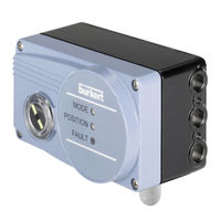
Burkert 8791 Operating Instructions Manual (186 pages)
Electropneumatic positioner
Brand:
Burkert
| Category:
Valve Positioners
| Size: 5.47 MB
Table of Contents
English
3
Table of Contents
3
Operating Instructions
7
Symbols
7
Type
7
Authorized Use
8
Predictable Misuse
8
Basic Safety Instructions
9
General Information
10
Scope Of Supply
10
Contact Addresses
10
Warranty
11
Restrictions
8
Information On The Internet
11
Description of System
12
Features
12
General Description
12
Combination with Valve Types and Mounting Versions
13
Overview of the Mounting Options
14
Structure
15
Representation
15
Function
16
Function Diagram
16
Function Of The Position Control
17
Schematic Representation Of The Position Control
18
Properties Of The Position Controller Software
19
Functions I
19
Functions II
19
Interfaces Of The Positioner
21
Technical Data
22
Safety Positions After Failure Of The Electrical Or Pneumatic Auxiliary Power
22
Type
22
Factory Settings Of The Positioner
23
Functions Can be Activated Via DIP Switches
23
Functions Can be Activated Via Communications Software
23
Positioner Specifications
24
Operating Conditions
24
Conformity
24
Mechanical Data
24
Electrical Data
25
Electrical Data with as Interface Bus Control (Optional)
25
Pneumatic Data
26
Operating
27
Safety Instructions
27
Operating Status
27
Control And Display Elements Of The Positioner
27
Configuration of the Keys
28
Function of the DIP Switches
29
Display of the Leds
30
Error Messages
31
Error Messages in MANUAL and AUTOMATIC Operating Status
31
Error Messages While the X.TUNE Function Is Running
31
Functions
32
Basic Functions
32
DIR.CMD - Effective Sense of Direction of the Position Controller Set-Point Value
33
CUTOFF - Sealing Function for the Position Controller
34
And Stroke
35
Additional Functions
36
Attachment and Assembly
37
Safety Instructions
37
Attachment To A Proportional Valve With Namur Linear Actuators
38
Attachment Kit for Linear Actuators (Serial No. 787 215)
38
Type
38
11.2.2. Installation
39
Attaching Mounting Bracket
41
Aligning Lever Mechanism
42
Attachment To A Proportional Valve With Rotary Actuator
43
Mounting Kit on Rotary Actuator (Part No. 787338)
43
11.3.2. Installation
43
Remote Operation With External Position Measuring System
46
Mounting Accessories
46
Connection and Start-Up of the Remote Sensor Type 8798
47
Fluid Connection
48
Safety Instructions
48
Electrical Connection
50
Safety Instructions
50
Electrical Connection With Circular Plug-In Connector
50
Designation of the Circular Plug-In Connector
50
Pin Assignment for Input Signals from the Control Centre (E.g. PLC) - M12, 8-Pole Plug
51
Pin Assignment for Output Signals to the Control Centre (E.g. PLC) - M 12, 8-Pole Plug (Required for Analogue Output Option Only)
51
Pin Assignment for Operating Voltage - M12, 8-Pole Circular Plug-In Connector
51
Electrical Connection With Cable Gland
52
Designation of the Screw-Type Terminals
52
Terminal Assignment for Input Signals from the Control Centre (E.g. PLC)
52
Terminal Assignment for Output Signals to the Control Centre (E.g. PLC) (Required for Analogue Output Option Only)
53
Terminal Assignment for Operating Voltage
53
Terminal Assignment for Connecting the External Position Measuring System (for Remote Model Only)
53
Connection of the Terminals
53
Start-Up
54
Safety Instructions
54
Specifying The Standard Settings
54
Running the Automatic Adjustment X.TUNE
54
Type
55
As Interface
56
As Interface Connection
56
Technical Data For As Interface Pcbs
56
Programming Data
56
Led Status Display (Bus)
57
Electrical Connection As Interface
58
Safety Instructions
58
Connection with M12 Circular Plug-In Connector, 4-Pole, Male
58
Service
59
Pactware 3.6
60
Serial Interface Rs 232
60
Accessories
60
Communications Software
60
Download
61
Packaging and Transport
62
Storage
62
Disposal
62
Deutsch
63
Die Bedienungsanleitung
67
Darstellungsmittel
67
Beschränkungen
68
Bestimmungsgemässe Verwendung
68
Vorhersehbarer Fehlgebrauch
68
Grundlegende Sicherheitshinweise
69
Allgemeine Hinweise
70
Lieferumfang
70
Kontaktadressen
70
Gewährleistung
71
Informationen IM Internet
71
Allgemeine Beschreibung
72
Merkmale
72
Systembeschreibung
72
Kombination mit Ventiltypen und Anbauvarianten
73
Übersicht der Anbaumöglichkeiten
74
Darstellung
75
Funktion
76
Aufbau
75
Funktionsschema
76
Funktion Der Stellungsregelung
77
Schematische Darstellung Der Stellungsregelung
78
Eigenschaften Der Stellungsregler-Software
79
Funktionen I
79
Funktionen II
79
Schnittstellen Des Positioners
81
Technische Daten
82
Sicherheitsstellungen Nach Ausfall Der Elektrischen Bzw. Pneumatischen Hilfsenergie
82
Werkseinstellungen Des Positioners
83
Über DIP-Schalter Aktivierbare Funktionen
83
Über Kommunikationssoftware Aktivierbare Funktionen
83
Daten Des Positioners
84
Betriebsbedingungen
84
Konformität
84
Mechanische Daten
84
Elektrische Daten
85
Elektrische Daten mit Busansteuerung AS-Interface (Optional)
85
Pneumatische Daten
86
Bedienung
87
Sicherheitshinweise
87
Betriebszustand
87
Bedien- Und Anzeigeelemente Des Positioners
87
Belegung der Tasten
88
Funktion der DIP-Schalter
89
Anzeige der Leds
90
Fehlermeldungen
91
Fehlermeldungen in den Betriebszuständen HAND und AUTOMATIK
91
Fehlermeldungen bei der Durchführung der Funktion X.TUNE
91
Funktionen
92
Grundfunktionen
92
DIR.CMD - Wirkrichtung (Direction) des Stellungsregler-Sollwertes
93
CUTOFF - Dichtschließfunktion für den Stellungsregler
94
Und Hub
95
Zusatzfunktionen
96
Anbau und Montage
97
Sicherheitshinweise
97
Anbau An Ein Stetigventil Mit Schubantrieb Nach Namur
98
Anbausatz an Schubantriebe (ID.-Nr. 787 215)
98
11.2.2. Montage
99
Anbauwinkel Befestigen
101
Hebelmechanismus Ausrichten
102
Anbau An Ein Stetigventil Mit Schwenkantrieb
103
Anbausatz an Schwenkantrieb (ID.-Nr. 787338)
103
11.3.2. Montage
103
Remote-Betrieb Mit Externem Wegmesssystem
106
Befestigungszubehör
106
Anschluss und Inbetriebnahme des Remote-Sensors Typ 8798
107
Fluidischer Anschluss
108
Sicherheitshinweise
108
Elektrischer Anschluss
110
Sicherheitshinweise
110
Elektrische Installation Mit Rundsteckverbinder
110
Bezeichnung der Rundsteckverbinder
110
Pin-Belegung für Eingangssignale der Leitstelle (Z.b. SPS) - Stecker M12, 8-Polig
111
Pin-Belegung für Ausgangssignale zur Leitstelle (Z.b. SPS) - Stecker M12, 8-Polig (nur bei Option Analoger Ausgang)
111
Pin-Belegung für Spannungsversorgung - Rundstecker M12, 8-Polig
111
Elektrische Installation Mit Kabelverschraubung
112
Bezeichnung der Schraubklemmen
112
Klemmenbelegung für Eingangssignale der Leitstelle (Z. B. SPS)
112
Klemmenbelegung für Ausgangssignale zur Leitstelle (Z.b. SPS) - (nur bei Option Analoger Ausgang Erforderlich)
113
Klemmenbelegung für Spannungsversorgung
113
Klemmenbelegung für Externes Wegmesssystem (nur bei Remote-Ausführung)
113
Anschluss der Klemmen
113
Inbetriebnahme
114
Sicherheitshinweise
114
Festlegen Der Grundeinstellungen
114
Ausführen der Automatischen Anpassung X.TUNE
114
As-Interface
116
As-Interface-Anschaltung
116
Technische Daten Für As-Interface-Leiterplatten
116
Programmierdaten
116
Led Zustandsanzeige Bus
117
Anschluss mit Rundsteckverbinder M12, 4-Polig, Male
118
Wartung
119
Sicherheitshinweise
118
Elektrische Installation As-Interface
118
Serielle Schnittstelle Rs 232
120
Zubehör
120
Pactware 3.6
120
Kommunikationssoftware (Pc-Software Auf Fdt/Dtm Technologie)
120
Download
121
Entsorgung
122
Lagerung
122
Verpackung, Transport
122
Français
123
Ce Manuel D'utilisation
127
Symboles
127
Mauvaise Utilisation Prévisible
128
Utilisation Conforme
128
Consignes de Sécurité Fondamentales
129
Indications Générales
130
Fourniture
130
Adresses
130
Garantie Légale
131
Informations Sur Internet
131
Description du Système
132
Restrictions
128
Caractéristiques
132
Description Générale
132
Combinaison Avec Types de Vanne et Variantes de Montage
133
Vue D'ensemble des Possibilités de Montage
134
Représentation
135
Fonction
136
Schéma Fonctionnel
136
Structure
135
Fonction De La Régulation De Position
137
Représentation Schématique De La Régulation De Position
138
Propriétés Du Logiciel Du Positionneur
139
Fonctions I
139
Fonctions II
139
Interfaces Du Positionneur
141
Caractéristiques Techniques
142
Positions De Sécurité Après Une Panne D'énergie Auxiliaire Électrique Ou Pneumatique
142
Réglages Usine Du Positionneur
143
Fonctions Activables Avec Interrupteur DIP
143
Fonctions Activables Avec le Logiciel de Communication
143
Caractéristiques Du Positionneur
144
Conditions D'exploitation
144
Conformité
144
Caractéristiques Mécaniques
144
Caractéristiques Électriques
145
Caractéristiques Électriques Avec Commande Bus Interface as (en Option)
145
Caractéristiques Pneumatiques
146
Commande
147
Consignes De Sécurité
147
Eléments De Commande Et D'affichage Du Positionneur
147
Etat De Marche
147
Affectation des Touches
148
Fonction des Interrupteurs DIP
149
Affichage des LED
150
Messages D'erreur
151
Messages D'erreur Dans les États de Marche MANUEL et AUTOMATIQUE
151
Messages D'erreur Lors de L'exécution de la Fonction X.TUNE
151
Fonctions
152
Fonctions De Base
152
DIR.CMD - Sens D'action (Direction) de la Valeur de Consigne du Positionneur
153
CUTOFF - Fonction de Fermeture Étanche du Positionneur
154
CHARACT - Caractéristique de Transfert entre le Signal D'entrée
155
(Valeur de Consigne de Position) et la Course
155
Fonctions Supplémentaires
156
Ajout et Montage
157
Consignes De Sécurité
157
Montage Sur Une Vanne De Régulation À Actionneur Linéaire Selon Namur
158
Jeu de Montage Sur Actionneurs Linéaires (N° ID 787 215)
158
11.2.2. Montage
159
Fixer L'équerre de Montage
161
Aligner le Mécanisme du Levier
162
Montage Sur Une Vanne De Régulation Avec Actionneur Pivotant
163
Jeu de Montage Sur Actionneur Pivotant (N° ID 787338)
163
11.3.2. Montage
163
Mode Remote Avec Système De Mesure De Déplacement Externe
166
Accessoires de Fixation
166
Raccordement et Mise en Service du Capteur Remote Type 8798
167
Raccord Fluidique
168
Consignes De Sécurité
168
Raccordement Électrique
170
Consignes De Sécurité
170
Raccordement Avec Connecteur Rond
170
Désignation des Connecteurs Ronds
170
Affectation des Broches; Signaux D'entrée du Poste de Commande (Par Ex. API) - Connecteur M12, 8 Pôles
171
Affectation des Broches; Signaux de Sortie Vers le Poste de Commande (Par Ex. API) - Connecteur M12, 8 Pôles (Uniquement Avec L'option Sortie Analogique)
171
Affectation des Broches; Tension de Service - Connecteur Rond M12, 8 Pôles
171
Raccordement Avec Presse-Étoupe
172
Désignation des Bornes Vissées
172
Affectation des Bornes pour Signaux D'entrée du Poste de Commande (Par Ex. API)
172
Affectation des Bornes pour Signaux de Sortie Vers le Poste de Commande (Par Ex. API) - (Nécessaire Uniquement Avec L'option Sortie Analogique)
173
Affectation des Bornes pour Tension de Service
173
Affectation des Bornes pour Raccordement du Système de Mesure de Déplacement Externe (Uniquement pour la Version Remote)
173
Raccordement des Bornes
173
Mise en Service
174
Consignes De Sécurité
174
Détermination Des Réglages De Base
174
Exécution de L'adaptation Automatique X.TUNE
174
Interface as
176
Connexion Interface As
176
Caractéristiques Techniques Pour Circuits Imprimés Interface As
176
Données De Programmation
176
L'affichage D'état Led Bus
177
Raccordement Électrique Interface As
178
Consignes de Sécurité
178
Raccordement Avec Connecteur Rond M12, 4 Pôles, Mâle
178
Maintenance
180
Accessoires
181
Logiciel De Communication (Logiciel Pc Sur Technologie Fdt/Dtm)
181
Pactware 3.6
181
Interface Sérielle Rs 232
181
Téléchargement
182
Elimination
183
Emballage, Transport
183
Stockage
183
Advertisement
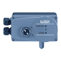
Burkert 8791 Operating Instructions Manual (72 pages)
Positioner SideControl BASIC Electropneumatic positioner
Brand:
Burkert
| Category:
Valve Positioners
| Size: 1.77 MB
Table of Contents
Table of Contents
3
1 Operating Instructions
8
Symbols
8
Definition of Term / Abbreviation
8
2 Authorized Use
9
3 Basic Safety Instructions
10
4 General Information
11
Contact Addresses
11
Warranty
11
Information on the Internet
11
5 Description of System
12
General Description
12
Features
12
Combination with Valve Types and Mounting Versions
13
Optionally External Position Feedback with Inductive Proximity Switch
13
Overview of the Mounting Options
14
6 Structure
15
Representation
15
7 Function
16
Function Diagram
16
Function of the Position Control
17
Schematic Representation of the Position Control
18
Properties of the Positioner Software
19
Functions I
19
Functions II
20
Interfaces of the Positioner
21
8 Technical Data
22
Conformity
22
Standards
22
Operating Conditions
22
Mechanical Data
22
Electrical Data
23
Electrical Data 24 V DC
23
Electrical Data with AS-Interface Bus Control (Optional)
23
Pneumatic Data
24
Safety End Positions after Failure of the Electrical or Pneumatic Auxiliary Power
25
Factory Settings of the Positioner
26
Functions Can be Activated Via DIP Switches
26
Functions Can be Activated Via Communications Software
26
9 Operating
27
Safety Instructions
27
Operating Status
27
Control and Display Elements of the Positioner
27
Configuration of the Keys
28
Function of the DIP Switches
29
Display of the Leds
30
Error Messages
31
Error Messages in MANUAL and AUTOMATIC Operating Status
31
Error Messages While the X.TUNE Function Is Running
31
10 Functions
32
Basic Functions
32
Dir.CMD
33
Effective Sense Of Direction Of The Positioner Set-Point Value
33
Cutoff
34
Sealing Function for the Positioner
34
CUTOFF Sealing Function for the Positioner
34
Charact
35
Transfer Characteristic between Input Signal (Position Set-Point Value) and Stroke
35
Input
37
Enter the Input Signal
37
INPUT Enter the Input Signal
37
Reset
38
Reset to Factory Settings
38
X.tune
38
Automatic Adjustment of the Positioner to the Relevant Operating Conditions
38
RESET Reset to Factory Settings
38
Additional Functions
39
Dir.actuator
39
Effective Direction Of The Actuator
39
Type
39
SPLITRANGE - Signal Split Range
40
X.limit
41
Limiting the Mechanical Stroke Range
41
X.LIMIT Limiting the Mechanical Stroke Range
41
X.time
42
Limiting the Control Speed
42
X.TIME Limiting the Control Speed
42
X.control
43
Parameterization of the Positioner
43
SAFE POSITION - Definition of the Safe Position
43
X.CONTROL Parameterization of the Positioner
43
Signal Error
44
Configuration Of Signal Level Fault Detection
44
Binary Input
44
Activation of the Binary Input
44
OUTPUT (Optional)
45
OUTPUT (Optional) - Configuration of the Analog Output
45
11 Attachment and Assembly
46
Safety Instructions
46
Attachment To A Proportional Valve With Namur Linear Actuators
47
Attachment Kit (IEC 534-6) for Linear Actuators (Order No. 787215)
47
Installation
48
Attaching Mounting Bracket
50
Aligning Lever Mechanism
51
Attachment To A Proportional Valve With Rotary Actuator
52
Attachment Kit (VDI/VDE 3845) on Rotary Actuator (Order No. 787338)
52
Installation
52
Remote Operation With External Position Sensor
55
Mounting Accessories
55
Connection and Start-Up of the Remote-Sensor Type 8798
56
12 Fluid Connection
57
Safety Instructions
57
13 Electrical Connection
59
Safety Instructions
59
Electrical Connection With Circular Plug-In Connector
59
Designation of the Circular Plug-In Connector
59
Pin Assignment for Input Signals from the Control Centre (E.g. PLC) - M12, 8-Pole Plug
60
Pin Assignment for Output Signals to the Control Centre (E.g. PLC) - M12, 8-Pole Plug (Required for Analogue Output Option Only)
60
Pin Assignment for Operating Voltage - M12, 8-Pole Circular Plug-In Connector
60
Type
60
Electrical Connection With Cable Gland
61
Designation of the Screw-Type Terminals
61
Connection of the Screw-Type Terminals
61
Terminal Assignment for Input Signals from the Control Centre (E.g. PLC)
61
Terminal Assignment for Output Signals to the Control Centre (E.g. PLC) (Required for Analogue Output Option Only)
62
Terminal Assignment for Operating Voltage
62
Terminal Assignment for External Position Sensor (for Remote Model Only)
62
14 Start-Up
63
Safety Instructions
63
Specifying The Standard Settings
63
Running the Automatic Adjustment X.TUNE
63
15 As-Interface
65
AS-Interface Connection
65
Communication Sequence for the Version S-7.A.5 Profile
66
Led Status Display (Bus)
67
Electrical Connection As-Interface
68
Safety Instructions
68
Connection with M12 Circular Plug-In Connector, 4-Pole, Male
68
16 Service
69
17 Accessories
69
Communications Software
70
USB Interface
70
Download
70
Packaging and Transport
71
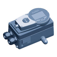
burkert 8791 Quick Start Manual (40 pages)
Positioner SideControl BASIC
Brand:
burkert
| Category:
Valve Positioners
| Size: 1.41 MB
Table of Contents
Table of Contents
3
1 About These Instructions
5
Symbols
5
Definition of Terms
5
2 Intended Use
6
3 Basic Safety Instructions
6
4 General Information
7
Contact Addresses
7
Warranty
7
Information on the Internet
7
5 Description of System
8
Structure
8
General Description
8
6 Technical Data
9
Conformity
9
Standards
9
Operating Conditions
9
Mechanical Data
9
Type Label
9
Electrical Data
10
Pneumatic Data
11
7 Operating
11
Operating Status
11
Control and Display Elements of the Positioner
12
8 Attachment and Assembly
17
Installation of Devices for the Hazardous Area
17
Attachment to a Continuous Valve with Linear Actuators According to NAMUR
17
Attachment to a Continuous Valve with Rotary Actuator
21
Remote Operation with External Position Sensor
24
9 Fluid Connection
25
Connection of Devices for the Hazardous Area
25
Safety Instructions
25
Safety End Positions
26
10 Electrical Connection
28
Connection of Devices for the Hazardous Area
28
10.2 Safety Instructions
28
Electrical Connection Without Fieldbus Communication
28
10.4 Electrical Installation, IO-Link
33
10.5 Electrical Installation, Büs
33
11 Start-Up
34
Safety Instructions
34
Specifying the Standard Settings
34
Setting With Bürkert Communicator
35
IO-Link
36
Büs
36
Accessories
37
Packaging, Transport, Storage
38
Advertisement
Bürkert 8791 Quick Start Manual (38 pages)
SideControl BASIC Electropneumatic positioner
Brand:
Bürkert
| Category:
Valve Positioners
| Size: 3.66 MB
Table of Contents
Table of Contents
3
Definition of Term / Abbreviation
5
Quickstart
5
Symbols
5
Authorized Use
6
Restrictions
6
Basic Safety Instructions
7
General Information
8
Description Of System
8
Contact Addresses
8
Structure
8
Technical Data
9
General Description
9
Conformity
9
Standards
9
Operating Conditions
9
Mechanical Data
10
Electrical Data
10
Electrical Data with AS-Interface Bus Control (Optional)
11
Pneumatic Data
11
Operating
12
Operating Status
12
Control and Display Elements of the Positioner
12
Error Messages
16
Attachment And Assembly
17
Installation of Devices for the Hazardous Area
17
Actuators
17
Attachment to a Proportional Valve with Rotary Actuator
21
Remote Operation with External Position Sensor
24
Fluid Connection
25
Connection of Devices for the Hazardous Area
25
Safety Instructions
25
Safety End Positions
26
Electrical Connection
28
Connection of Devices for the Hazardous Area
28
Safety Instructions
28
Electrical Connection with Circular Plug-In Connector
28
M12, 8-Pole
28
Electrical Connection with Cable Gland
30
Electrical Installation AS-Interface
32
LED Status Display AS-Interface
33
Start-Up
34
Safety Instructions
34
Specifying the Standard Settings
34
Accessories
35
Packaging, Transport, Storage
36
Burkert 8791 Assembly Instructions Manual (16 pages)
External position feedback option with inductive proximity switch
Brand:
Burkert
| Category:
Valve Positioners
| Size: 1.16 MB
Table of Contents
Authorized Use
2
Basic Safety Instructions
2
Warranty
2
Technical Data
3
Electrical Connection
4
Bestimmungsgemässe Verwendung
7
Grundlegende Sicherheitshinweise
7
Gewährleistung
7
Technische Daten
8
Montage
8
Elektrischer Anschluss
9
Instructions de Montage
11
Utilisation Conforme
12
Consignes de Sécurité Fondamentales
12
Garantie Légale
12
Caractéristiques Techniques
13
Raccordement Électrique
14
Bürkert 8791 Assembly Instructions Manual (16 pages)
Brand:
Bürkert
| Category:
Valve Positioners
| Size: 1.11 MB
Table of Contents
Authorized Use
2
Basic Safety Instructions
2
Warranty
2
Technical Data
2
Electrical Connection
4
Bestimmungsgemässe Verwendung
7
Grundlegende Sicherheitshinweise
7
Gewährleistung
7
Technische Daten
7
Montage
8
Elektrischer Anschluss
9
Instructions de Montage
11
Utilisation Conforme
12
Consignes de Sécurité Fondamentales
12
Caractéristiques Techniques
12
Raccordement Électrique
14
Advertisement
Related Products
Bürkert 8643 PA
Bürkert 8012 Series
Bürkert LEVEL SWITCH 8110
Bürkert 8695
Bürkert 8136
Bürkert 8228 ELEMENT
Bürkert 8619 multiCELL WM AC
Bürkert 8633
Bürkert 8600
Bürkert 8220
Bürkert Categories
Control Unit
Measuring Instruments
Controller
Transmitter
Valve Positioners
More Bürkert Manuals
Login
Sign In
OR
Sign in with Facebook
Sign in with Google
Upload manual
Upload from disk
Upload from URL