Table of Contents
Advertisement
Quick Links
1.1 Introduction ................................................................................................................. 1
1.2 Specifications.............................................................................................................. 1
2.1 Connector Locations and Dimensions ........................................................................ 4
2.2 Installation Steps......................................................................................................... 5
2.3 2.3 Installing a DIMM .................................................................................................. 6
2.4 Central Processing Unit (CPU) ................................................................................... 6
2.5 Setting Jumpers........................................................................................................ 12
2.5.1 Clear CMOS (JCC) ................................................................................................ 12
2.5.2 BIOS-protect Jumper (JAV) ................................................................................... 12
2.5.3 DVI Connector Jumper(J1,J2,J3,J4) ......................................................... 14
2.6 External Connector ................................................................................................... 15
2.6.1 SATA Connector(SATA1,SATA2) .................................................................... 15
2.6.2 Serial port(COM)............................................................................................... 16
2.6.3 Display Connector(DVIB,DVIC)...................................................................... 16
2.6.4 USB&Ethernet ports(USB,LAN_USB.USB1-3)................................................. 19
2.6.5 LAN LED(LAN_LED)......................................................................................... 21
2.6.6 Keyboard and Mouse port(PS/2) ...................................................................... 21
2.6.7 IRDA interface(IRDA)........................................................................................ 23
2.6.8 GPIO(GPIO)...................................................................................................... 24
2.6.9 Power Supply Connectors (ATX,PWR).................................................................. 25
2.6.10 Fan Socket(CPUFAN1,CPUFAN2,SYS_FAN) ................................................ 26
2.6.11 Audio Port(AUDIO,J5) .......................................................................................... 27
2.6.12 Front Panel connector(FRONT)...................................................................... 28
2.6.13 RAM Socket(DIMM 1,DIMM 2
2.6.14 Mini PCI-E Slot(Mini PCI-E) ............................................................................ 31
Contents
..................................................................................... 1
.............................................................................. 4
Ⅲ
..................................................................................................... 32
Advertisement
Table of Contents

Related Manuals for Norco MITX-6891


Summary of Contents for Norco MITX-6891
-
Page 1: Table Of Contents
Contents Chapter1 General Information ..................1 1.1 Introduction ......................... 1 1.2 Specifications......................1 Chapter2 Installation Instructions ................4 2.1 Connector Locations and Dimensions ................ 4 2.2 Installation Steps......................5 2.3 2.3 Installing a DIMM ....................6 2.4 Central Processing Unit (CPU) ................... 6 2.5 Setting Jumpers...................... - Page 2 3.1 Standard CMOS Setup ..................... 33 3.2 Advanced BIOS Features ..................36 3.2.1 CPU Feature......................36 3.2.2 Removable Device Priority ..................38 3.2.3 Hard Disk Boot Priority ..................38 3.2.4 CD-ROM Boot Priority ................... 39 3.3 Advanced Chipset Features..................42 3.4.1 OnChip IDE Device....................
-
Page 3: Packing List
Packing List Thank you very much for choosing our products. Please check your package completely as the following item checklist first, if you find any components lost or damaged, please contact your retailer. ■ MITX-6891 motherboard 1pcs ■User’s Manual 1pcs ■Drive Disk... -
Page 4: Chapter1 General Information
Chapter 1 General Information... -
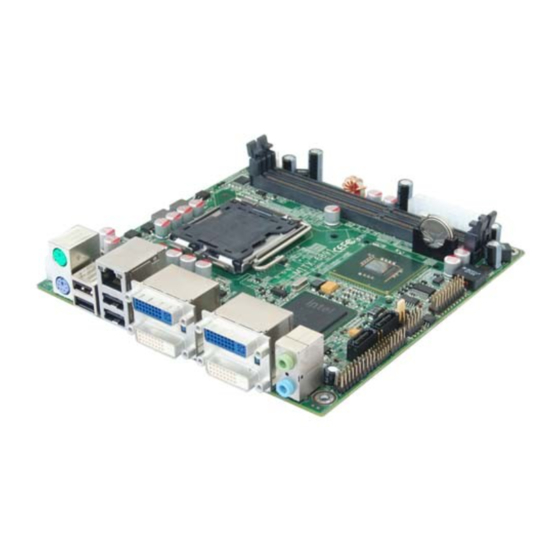
Page 5: Introduction
MITX-6891 is High Performance Mini-ITX motherboard based on Intel G45+ICH10 chipset ,supports Intel® Virtualization Technology LGA775 Intel® Core™2 Duo、 Intel® Core™2 Quad and Intel® Celeron®440 (Conroe-L) processor. .MITX-6891 has two 240-pin DDRⅢ 800/1066MHz DIMM socket support system memory max. upto 2GB. Northbridge integrated Intel GMA X4500, 4xDVI video output (3x DVI-D, 1x DVI-I). - Page 6 ●Chipshet:Intel®G45 integration Intel® Graphics Media Accelerator X4500HD ●DVI:Onboard DVI Display Controlle(G45 integration) ,3x DVI-D output,1x DVI-I output (DVI-I Signal can be convert to VGA signal).Support resolution up to 2560x1600 ●MITX-6891 has two 240 Pin DIMM DDR 800/1066MHz socket support system memory max. Ⅲ...
- Page 7 MITX-6891 Mini-ITX Motherboard Based on Intel G45 Chipset I/0 Functions ●IO Chipset: Winbond W83627DHG ●Provide One 2x5Pin serial port,support RS232 ●Norma PS/2 keyboard and mouse port ●1x IrDA port ●Programmable input/output interfaces,2x6Pin,6input/6output Power Supply ●+12V plug + Standard ATX PowerSupply Watchdog ●Support H/W reset function...
-
Page 8: Chapter2 Installation Instructions
Chapter 2 Installation Instructions... -
Page 9: Connector Locations And Dimensions
Chapter2 Installation Instructions 2.1 Connector Locations and Dimensions The following picture is interface index for MITX-6891, when you install your devices, please consult it and read the following guide. During installation please care: for some devices, if incorrectly install, it will not work normally. -
Page 10: Installation Steps
MITX-6891 Dimensions 2.2 Installation Steps Please refer to the following steps to install your computer: 1. Adjust all Jumpers on the MITX-6891 per this manual. 2. Installing System memory 3:Installing CPU and CPUFAN 4. Connect all of the signal line, cable, panel-control circuitry and power supply 5. -
Page 11: Installing A Dimm
MITX-6891 Mini-ITX Motherboard Based on Intel G45 Chipset 1. Disconnect your Computer from the power supply before handling it. 2. Hold side by the edges; don't touch any component or pins on the board 3. Use a grounded wrist strap while getting in touch with integrated circuit component (like as CPU, RAM). - Page 12 MITX-6891 Mini-ITX Motherboard Based on Intel G45 Chipset system work steadily, please set your CPU exterior frequency by its specification, and we don’t suggest you over clock your CPU. At present most Intel ® CPU frequency multiplication have been set when them leave factory, can not be changed.
- Page 13 MITX-6891 Mini-ITX Motherboard Based on Intel G45 Chipset 4:Lift the load plate with your thumb and forefinger to a 100º angle (A), then push the PnP cap from the load plate window to remove (B). 5:Position the CPU over the socket, making sure that the gold triangle is on the bottom‑left corner of the socket then fit the socket alignment key into the CPU notch.
- Page 14 MITX-6891 Mini-ITX Motherboard Based on Intel G45 Chipset 2.4.2 Installing the CPU heatsink and fan To install the CPU heatsink and fan:: 1: Place the heatsink on top of the installed CPU, making sure that the four fasteners match the holes on the motherboard.
- Page 15 MITX-6891 Mini-ITX Motherboard Based on Intel G45 Chipset situation. 2.3.3 Uninstalling the CPU heatsink and fan To uninstall the CPU heatsink and fan: 1:Disconnect the CPU fan cable from the connector on the motherboard. 2:Rotate each fastener counterclockwise. 3:Pull up two fasteners at a time in a diagonal sequence to disengage the heatsink and fan assembly from the motherboard.
- Page 16 MITX-6891 Mini-ITX Motherboard Based on Intel G45 Chipset 5:Rotate each fastener clockwise to ensure correct orientation when reinstalling. The narrow end of the groove should point outward after resetting. (The photo shows the groove shaded for emphasis.).
-
Page 17: Setting Jumpers
MITX-6891 Mini-ITX Motherboard Based on Intel G45 Chipset 2.5 Setting Jumpers Jumpers are located on the motherboard, they represent clear CMOS jumper JCC etc. pin1 for all jumpers are located on the side with a thick white arrow refer to the motherboard’s silkscreen , jumpers with three pins will be shown as 1-2 to represent pin1&pin2 connected and... - Page 18 MITX-6891 Mini-ITX Motherboard Based on Intel G45 Chipset The BIOS of the CPU card is contained in the Flash ROM. If the jumper JAV1 is set as dosed, you will be unable to flash the BIOS. However in this status, the system BIOS is protected from being attacked by serious virus such CIH virus.
-
Page 19: Dvi Connector Jumper(J1,J2,J3,J4
MITX-6891 Mini-ITX Motherboard Based on Intel G45 Chipset 2.5.3 DVI Connector Jumper(J1,J2,J3,J4) The motherboard provides 3x DVI-D output and 1x DVI-I output, J1, J2 to set DVIC, J3, J4 to set DVIB. When the J1, J2 is set to 1-2.When the J1, J2 is set to 1-2, the bridge chip only DVIC-1 signal, if connected to a display, please take in the DVIC-1.When the J1, J2 is set to 2-3,... -
Page 20: External Connector
MITX-6891 Mini-ITX Motherboard Based on Intel G45 Chipset 2.6 External Connector Please carefully read this manual when connecting external connector, so as to avoid damage to the motherboard! 2.6.1 SATA Connector(SATA1,SATA2) The board provide 2 Serial ATAⅡ Ports, The transfer speed is up to 300MB/s. -
Page 21: Serial Port(Com
MITX-6891 Mini-ITX Motherboard Based on Intel G45 Chipset 2.6.2 Serial port(COM) The motherboard provide one serial port,support RS232 transmission mode。 COM: Pin Name Pin Name HDCD1- HDSR1- HRXD1 HRTS1- HTXD1 HCTS1- HDTR1- HRI1- 2.6.3 Display Connector(DVIB,DVIC) The board provides 3x DVI-D output,1x DVI-I, DVI-I(DVIC-2)Signal can be convert to VGA signal, Use the adaptor to change the standard DVI-I interface to VGA interface(DB15).DVI... - Page 22 MITX-6891 Mini-ITX Motherboard Based on Intel G45 Chipset DVIB-1: Pin Name Pin Name D2-A D2+A SC-DDC_A SD-DDC_A D1-A D1+A VCC5 HDMI_PLUG_A D0-A D0+A CLK+A CLK-A DVIB-2: Pin Name Pin Name D2-B D2+B...
- Page 23 MITX-6891 Mini-ITX Motherboard Based on Intel G45 Chipset SC-DDC_B SD-DDC_B D1-B D1+B VCC5 HDMI_PLUG_B D0-B D0+B CLK+B CLK-B DVIC-1: Pin Name Pin Name D2-C D2+C SC-DDC_C SD-DDC_C D1-C D1+C VCC5 HDMI_PLUG_C D0-C D0+C CLK+C CLK-C...
- Page 24 MITX-6891 Mini-ITX Motherboard Based on Intel G45 Chipset DVIC-2: Pin Name Pin Name D2-D D2+D SC-DDC_D SD-DDC_D D1-D D1+D VCC5 HDMI_PLUG_D D0-D D0+D CLK+D CLK-D 2.6.4 USB&Ethernet ports(USB,LAN_USB.USB1-3) The board provides up to seven USB Ports, One RJ45 Ethernet interface. thereinto,...
- Page 25 MITX-6891 Mini-ITX Motherboard Based on Intel G45 Chipset RJ45 PORT LED state description: Network link LILED state ACTLED(Yellow) state Message transfer status status Green(100Mbps) effective transfering Orang(1000Mbps) noneffective No message transfering Standard USB ports define: Pin Name USB DATA- USB DATA+ USB1,USB2,USB3ports define:...
-
Page 26: Lan Led(Lan_Led
MITX-6891 Mini-ITX Motherboard Based on Intel G45 Chipset USB DATA- USB DATA+ 2.6.5 LAN LED(LAN_LED) Pin Name Pin Name VCC3SB VCC3SB VCC3SB 2.6.6 Keyboard and Mouse port(PS/2) Two PS/2 ports for KB/MS: Green for Mouse and Purple for Keyboard. - Page 27 MITX-6891 Mini-ITX Motherboard Based on Intel G45 Chipset Mouse: Pin Name MS_DAT A MS_CLK Keyboard: Pin Name KB_DATA KB_CLK...
-
Page 28: Irda Interface(Irda
MITX-6891 Mini-ITX Motherboard Based on Intel G45 Chipset 2.6.7 IRDA interface(IRDA) This board provides a group of IrDA pins, supports IrDA version1.0 SIR or SHARP ASK-IR protocol infrared ray data transmission function. Pin Name IRRX IRTX... -
Page 29: Gpio(Gpio
MITX-6891 Mini-ITX Motherboard Based on Intel G45 Chipset 2.6.8 GPIO(GPIO) The board supports 12-bit GPIO through the GPIO connector. The 12 digital input/output can be programmed to read or control devices, with input or output defined. The default setting is 6 bits input and 6 bits output。... -
Page 30: Power Supply Connectors (Atx,Pwr)
MITX-6891 Mini-ITX Motherboard Based on Intel G45 Chipset 2.6.9 Power Supply Connectors (ATX, PWR) ATX Power supply,20PIN Special power supplies,with +12V plug。 ATX: Pin Name Pin Name +3.3V +3.3V -12V +3.3V PS-ON PW-OK +5V SB +12V PWR: Pin Name Pin Name... -
Page 31: Fan Socket(Cpufan1,Cpufan2,Sys_Fan
MITX-6891 Mini-ITX Motherboard Based on Intel G45 Chipset 2.6.10 Fan Socket(CPUFAN1,CPUFAN2,SYS_FAN) This board provide two 4Pin CPU fan socket(CPUFAN1,CPUFAN2)and one 3Pin system fan socket(SYS_FAN), attention: (1) Electric current for fan≤350mA (4.2W, 12V). (2) Please ensure that the fan wire is consistent with the wire for this socket. The power cord must be in the middle position. -
Page 32: Audio Port(Audio,J5)
MITX-6891 Mini-ITX Motherboard Based on Intel G45 Chipset 2.6.11 Audio Port(AUDIO,J5) The onboard audio controller provides SPEAKER-OUT or MIC-IN function, and you can recognize them by location (The MIC-IN is the jack near PCB, and the SPEAKER-OUT is at the far end of PCB) or color (Red is MIC-IN, and green is SPEAKER-OUT).The board provides one... -
Page 33: Front Panel Connector(Front
MITX-6891 Mini-ITX Motherboard Based on Intel G45 Chipset 2.6.12 Front Panel connector(FRONT) FRONT use to connect function button or LED on front panel. Front Panel connector Pin define: Pin Name Pin Name VCC5 VCC5 KELOCK- SPK- VCC5 SLEEPSW+ PWRBTN- VCC5... - Page 34 MITX-6891 Mini-ITX Motherboard Based on Intel G45 Chipset Particular connection as below, according to the table above, advert to their polarity; When relevant polarity connected wrong, relevant function won’t work normally. POWER LED SPERKER KEYLOCK SLEEP BUTTON POWER BUTTON GREEN LED...
-
Page 35: Ram Socket
(no matter which IDE device), LED will flash, shows that IDE device is running. Connect IDE LED on chassis panel and these pins (pin19 is LED anode). 2.6.13 RAM Socket(DIMMⅢ1,DIMMⅢ2) MITX-6891 has two 240 Pin DIMM DDRⅢ 800/1066MHz socket support system memory max. upto 4GB. -
Page 36: Mini Pci-E Slot(Mini Pci-E
MITX-6891 Mini-ITX Motherboard Based on Intel G45 Chipset 2.6.14 Mini PCI-E Slot(Mini PCI-E) The back device of motherboard provides a mini PCI-E slot, the user can expand mini PCI-E according to own need。... -
Page 37: Chapter3 Bios Setup
Chapter 3 BIOS Setup... - Page 38 MITX-6891 Mini-ITX Motherboard Based on Intel G45 Chipset Chapter3 BIOS Setup Award BIOS upgrade It is true that hardware and software are upgrading all the time. When your IPC can not support the newest processor (for example), you should upgrade the BIOS to try to keep up with the latest technology.
-
Page 39: Standard Cmos Setup
MITX-6891 Mini-ITX Motherboard Based on Intel G45 Chipset the sub-menu. 4. Use the “←↑→↓”and <Enter> to modify the value. 5. At any time, press<Esc> can back to the father-menu Note: The default BIOS settings for this motherboard apply for most conditions to ensure optimum performance. - Page 40 MITX-6891 Mini-ITX Motherboard Based on Intel G45 Chipset Note: If you intend to change the CMOS setting without restoring the previous backup, you have to click on "DEL" within two seconds of the "CMOS checksum error..." display screen message appearing. Then enter the "Setup" screen to modify the data. If the "CMOS checksum error"Message appears again and again, please check to see if you need to replace the battery...
- Page 41 MITX-6891 Mini-ITX Motherboard Based on Intel G45 Chipset 2. <Block Mode>: Turn this option to be On will help the R/W speed of HDD to be faster. But some of the old HDD don’t support this mode, and this option should be Off in this case.
-
Page 42: Advanced Bios Features
MITX-6891 Mini-ITX Motherboard Based on Intel G45 Chipset 3.2 Advanced BIOS Features 3.2.1 CPU Feature Delay Prior to Thermal When the temperature of CPU has reached the preset temperature by the factory, the clock of the motherboard will be delayed. The temperature device is activated, and the detector inside the CPU is also activated to maintain the limit of temperature of CPU. - Page 43 MITX-6891 Mini-ITX Motherboard Based on Intel G45 Chipset Choice of thermal management monitor。option:<Thermal Management 1(default)>, <Thermal Management 2>. TM2 Bus Ratio Performance Management bus will be activated when the hard mode detector turn hot from cool. Min=0 Max= 255 Input DEC code = Option :< 0X (Default)>.
-
Page 44: Removable Device Priority
MITX-6891 Mini-ITX Motherboard Based on Intel G45 Chipset Core Multi-Processing This option can ensure kernel load dual-processor in best way <Enabled>: use multi-kernel CPU,<Disabled>: use one of CPU. 3.2.2 Removable Device Priority The above-mentioned items are the order of boot devices, can not be amendment. -
Page 45: Cd-Rom Boot Priority
MITX-6891 Mini-ITX Motherboard Based on Intel G45 Chipset 3.2.4 CD-ROM Boot Priority The above-mentioned items are the order of boot devices, can not be amendment. Virus Warning If enabled, a warning message and alarm beep activates if someone attempts to write here.The commands are <Enabled>... - Page 46 MITX-6891 Mini-ITX Motherboard Based on Intel G45 Chipset The BIOS tries to load the OS with the devices in the sequence selected. Choices are: <Floppy>, <LS/ZIP>, <HDD>, <SCSI>, <CDROM>, <LAN>, and <Disabled>. Boot Other Device If this option is set as [Enabled], system can be booted from other devices if it is fail to boot from the first, second or third device.
- Page 47 MITX-6891 Mini-ITX Motherboard Based on Intel G45 Chipset OS Select For DRAM > 64MB This option allows the system to access greater than 64MB of DRAM memory when used with OS/2 that depends on certain BIOS calls to access memory. The default setting is <Non-OS/2>.
-
Page 48: Advanced Chipset Features
MITX-6891 Mini-ITX Motherboard Based on Intel G45 Chipset 3.3 Advanced Chipset Features System BIOS Cacheable The setting of Enabled allows caching of the system BIOS ROM at F0000h- FFFFFh, resulting in better system performance. However, if any program writes to this memory area, a system error may result. - Page 49 MITX-6891 Mini-ITX Motherboard Based on Intel G45 Chipset PCI Express Root Port Func PCI Express port 1-6 Set whether use PCI-E 1-6 port. The choices:<Auto(default)>,<Disabled>,<Enabled>. PCI-E Compliancy Mode This option allows you to choose the PCI-E Compliancy Mode. The choices:<v1.0a (default)>,<v1.0>.
- Page 50 MITX-6891 Mini-ITX Motherboard Based on Intel G45 Chipset DVMT Mode This item allows the user to adjust Intel's Dynamic Video Memory Technology (DVMT).Bios provides three options to choose (DVMT, FIXED and Both). Total GFX Memory This item displays the total system memory size.
-
Page 51: Onchip Ide Device
MITX-6891 Mini-ITX Motherboard Based on Intel G45 Chipset 3.4 Integrated peripherals 3.4.1 OnChip IDE Device IDE HDD Block Mode You can enable the Primary IDE channel and/or the Secondary IDE channel. Any channel not enabled is disabled. This field is for systems with only SCSI drives. - Page 52 MITX-6891 Mini-ITX Motherboard Based on Intel G45 Chipset IDE Primary/Secondary Master/Slave PIO Four IDE PIO(Programable Input and Output)options can allow you toassign PIO mode(1-4) for each IDE device.Mode 0 to 4 provides the increasing performance. In Auto mode, the system will auto detect the best working mode. The choices: <Auto>,<Mode 0>,...
-
Page 53: Super Io Device
MITX-6891 Mini-ITX Motherboard Based on Intel G45 Chipset 3.4.2 Super IO Device POWER ON Function Select the method to start the computer. Button only is use the power button to control. Keyboard 98 isuse some special power switch. Hotkey is use shortcut of Ctrl+F11 or ALT+F12. -
Page 54: Usb Device Setting
MITX-6891 Mini-ITX Motherboard Based on Intel G45 Chipset UART Mode Select This item allows you to select UART mode. The choices: < IrDA>, <ASKIR>, <Normal>. RxD, TxD Active This item allows you to determine the active of RxD, TxD. The Choices: <Hi, Hi,> ,<Lo, Lo,>... -
Page 55: Power Management Setup
MITX-6891 Mini-ITX Motherboard Based on Intel G45 Chipset have USB peripherals. The choices are <Enabled> and <Disabled>. USB 2.0 Controller This entry is used to disable/enable the USB 2.0 controller only. The BIOS itself may or may not have high-speed USB support. If the BIOS has high speed USB support built in, the support will automatically turn on when a high speed device is attached. - Page 56 MITX-6891 Mini-ITX Motherboard Based on Intel G45 Chipset PCI Express PM Function PEG Port ASPM The option:<Disabled>,<l0s>and<l1/l0s>. Root Port ASPM The option: <Disabled>,<l0s>,< l1>and<l1/l0s>. DMI Port ASPM The option: <los> and<Disabled>. ACPI Function (ACPI) This is item to activate the ACPI function. If you OS support ACPI-aware,For example: Windows 98SE/2000/ME,choice <Enabled>.Option:<Enabled>,<Disabled>.
- Page 57 MITX-6891 Mini-ITX Motherboard Based on Intel G45 Chipset This category allows you to select the type (or degree) of power saving and is directly related to the following modes: 1. HDD Power Down 2. Suspend Mode There are four selections for Power Management, three of which have fixed mode settings <User Define(default)>:Allows you to set each mode individually.When not disabled,each of...
- Page 58 MITX-6891 Mini-ITX Motherboard Based on Intel G45 Chipset If you choose “Instant-Off”, then pushing the ATX soft power switch button once will switch the system to “system off” power mode. You can choose “Delay 4 sec.” If you do, then pushing the button for more than 4 seconds will turn off the system, whereas pushing the button momentarily (for less than 4 seconds) will switch the system to “suspend”...
-
Page 59: Pnp/Pci Configurations
MITX-6891 Mini-ITX Motherboard Based on Intel G45 Chipset PCI PIRQ[A-D]# When Enabled, the system will resume from suspend mode if interrupt occurs. The choices :< Enabled>, <Disabled>. HPET Support The option:<Enabled(default)>,<Disabled>. HPET Mode The option:<32-bit mode (default)>,<64-bit mode>. 3.6 PnP/PCI Configurations Init Display First This option has two options: <PCI slot>/<AGP>,... - Page 60 MITX-6891 Mini-ITX Motherboard Based on Intel G45 Chipset cannot boot. Resources Controlled By The commands here are <Auto>or <Manual>.Choosing <manual> requires you to choose resources from each following sub-menu. <Auto> automatically configures all of the boot and Plug and Play devices but you must be using Windows 95 or above.
-
Page 61: Pc Health Status
MITX-6891 Mini-ITX Motherboard Based on Intel G45 Chipset 3.7 PC Health Status Annotate:(Green shows the following numerical values for the read-only) Shutdown Temperature Setup CPU Shutdown Temperature,This feature is only in ACPI mode effective. The option:<70°C/158°F (default)>,<60℃/ 140℉>,<65℃/ 149℉>,<Disabled>. CPU Warning Temperature The system will give an automatic warning if the CPU temperature goes over the selected setting.default setting :<... -
Page 62: Load Fail-Safe Defaults
MITX-6891 Mini-ITX Motherboard Based on Intel G45 Chipset 3.8 Load Fail-Safe Defaults If the system is not stable after installation, this function can be helpful. In this case, the system will cancel some of the function which enhance the system, and the system will run in very strict status. -
Page 63: Load Optimized Defaults
MITX-6891 Mini-ITX Motherboard Based on Intel G45 Chipset 3.9 Load Optimized Defaults Use this menu to load the BIOS default values that are factory settings for optimal performance system operations. While Award has designed the custom BIOS to maximize performance, the factory has the right to change these defaults to meet their needs.Press <Y>... -
Page 64: Set User Password
MITX-6891 Mini-ITX Motherboard Based on Intel G45 Chipset information ”ENTER PASSWORD” will be shows on screen,here you can input your password, do not be excess than 8 characters, then press enter, the password you inputted will replace the former one. Press enter again to confirm. -
Page 65: Exit Without Saving
MITX-6891 Mini-ITX Motherboard Based on Intel G45 Chipset If you select this and press <Enter>, the values entered in the setup utilities will be recorded in the CMOS memory of the chipset. The microprocessor will check this every time you turn your system on and compare this to what it finds as it checks the system. This record is required for the system to operate. -
Page 66: Appendix
Appendix... -
Page 67: Appendix 1: Driver Installation
MITX-6891 Mini-ITX Motherboard Based on Intel G45 Chipset Appendix Appendix 1: Driver Installation Please install the driver as per the following steps: Plug programme disk into CD-ROM, so installation of the driver can be made either automatically or mannually. Now mannually installation instructions are given as below: 1) A variety of options available regarding mannually installation, which you can check from Device Manager. -
Page 68: Appendix 2:Watchdog Programmer Guide
MITX-6891 Mini-ITX Motherboard Based on Intel G45 Chipset Appendix 2:Watchdog programmer guide watchdog reference code(ASM): -------------------------------------------------------------------------------------------------------------- Set the port to realize watchdog function through DEBUG order, so that it can carry out Watchdog Timer’s various functions. port instruction: 2EH :Address register 2FH :Data register... - Page 69 MITX-6891 Mini-ITX Motherboard Based on Intel G45 Chipset =========================================================== watchdog reference code(c++ language): ---------------------------------------------------------------------------------------------------- outputb (0x2e, 0x87) outputb (0x2e, 0x87) // Open SUPER IO register outputb (0x2e, 0x2B) outputb (0x2f, 0xE0) //bit4=0 ,set pin as watchdog func outputb (0x2E, 0x07)
-
Page 70: Appendix3:Gpio Instruction
Mini-ITX Motherboard Based on Intel G45 Chipset Appendix3:GPIO Instruction MITX-6891 provides a five way input and a five way output programable interface. Input and output of the interfaces are independent. In the GPIO interface, there are 12 Pin which are link to 10 digital bits. -
Page 71: Appendix 4: Glossary
MITX-6891 Mini-ITX Motherboard Based on Intel G45 Chipset Appendix 4: Glossary ACPI Advanced Configuration and Power Management Interface for short.ACPI specifications allow OS to control most power of computer and its extended devices. Windows 98/98SE, Windows 2000 and Windows ME are all support ACPI, it provide users a flexible system power management. - Page 72 MITX-6891 Mini-ITX Motherboard Based on Intel G45 Chipset Computer-Output Microfilmer.A universal serial communication interface, usually adopts normative OB 9 connector. DIMM: Dual Inline Memory Module. It’s a small circuit board with memory chipset, providing 64bit bus width. DRAM Dynamic Random Access Memorizer.It’s a normal type of memory often with a transistor and a capacitance to store 1 bit.
- Page 73 MITX-6891 Mini-ITX Motherboard Based on Intel G45 Chipset interface, and connect printer in a general way. POST Self-test when power on. While booting, BIOS will do once uninterrupted testing operation to the system, including RAM, keyboard, hard disk driver etc. Check them in normal situation and work well.
Need help?
Do you have a question about the MITX-6891 and is the answer not in the manual?
Questions and answers