Table of Contents
Advertisement
Quick Links
Advertisement
Table of Contents

Related Manuals for Norco MITX-6910


Summary of Contents for Norco MITX-6910
- Page 1 MITX-6910 Mini-ITX Industrial Motherboard USER’ Manual V1.0...
-
Page 2: Table Of Contents
Content Chapter 1. Product Introduction ....................1 1.1 Overview ...........................1 1.2 Product Specification ......................1 Chapter 2. Installation Instruction .....................4 2.1 Interface Location and Dimension Diagram ..............4 2.2 Installation Steps.......................4 2.3 CPU & Memory Installation ....................5 2.4 Jumper Setting........................5 2.4.1 CMOS Content Clearance/Hold Setting(JCC) ..........5 2.4.2 Anti-virus BIOS Write-protect Jumper Setting(JAV)... - Page 3 Chapter 3. BIOS Setup.......................27 BIOS Upgrading........................27 BIOS Parameter Configuration.....................27 BIOS Function Setup ......................27 3.1 Main Menu ........................28 3.2 Advanced Menu ......................29 3.2.1 ACPI Configuration....................29 3.2.2 CPU Configuration ....................30 3.2.3 SATA Configuration ....................31 3.2.4 USB Configuration....................32 3.2.5 Supper IO Configuration ..................33 3.2.6 H/W Monitor......................33 3.2.7 AMT Configuration....................34 3.2.8 Serial Port Console Redirection................35...
-
Page 4: Chapter 1 Product Introduction
Chapter 1 Product Introduction... -
Page 5: Overview
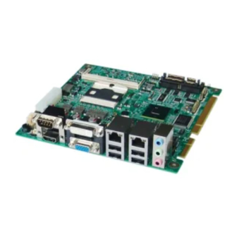
Chapter 1. Product Introduction 1.1 Overview MITX-6910 is a type of MINI-ITX motherboard based on Intel QM57 chipset, supporting Intel processor Core i7/Core i5/Celeron P4500 series. Board provides 2*240pin SODIMM sockets supporting DDRIII-800/1066MHz memory up to 8G; 2*SATA, 1*50pin CF socket; 8*USB, including 2* double layer standard USB ports and 2* 2×5Header interfaces. - Page 6 MITX-6910 Mini-ITX Motherboard Based on Intel QM57 ●2*SATA adopt 7+15PIN connector ●Compact Flash: 50Pin Socket ●1*Mini-PCIE SSD Display ●Controller: Intel QM57 integrated graphic controller ●VGA: 1* standard DB15 ●DVI: 1*DVI-I (DVI-D or DVI-A optional ) ●HDMI: 1* standard HDMI ●LVDS: dual channel 24bit LVDS ●Adopt Intel 82574L+ Intel 82577 chip...
- Page 7 MITX-6910 Mini-ITX Motherboard Based on Intel QM57 Expansion Interface ●2*Mini-PCIE(1*Mini-PCIE supports SSD) ●1*PCIEX4, 1*PCI Power Supply ● Standard ATX power supply Watchdog Timer ●Support HDD reset function BIOS ●64MB SPI Flash BIOS Environment ●Operating Temperature: 0-60℃(32℉-140℉) ●Storage Temperature: -40℃-80℃(-40℉-176℉) ●Operating Humidity: 5%-90% relative humidity, non-condensing.
-
Page 8: Chapter 2 Installation Instruction
Chapter 2 Installation Instruction... -
Page 9: Interface Location And Dimension Diagram
Chapter 2 Installation Instruction 2.1 Interface Location and Dimension Diagram Following picture is the interface index for MITX-6910, when you install your devices, please consult it and read the following guide. During installation please care for some devices. Improper installation will lead to system malfunctions. -
Page 10: Cpu & Memory Installation
MITX-6910 Mini-ITX Motherboard Based on Intel QM57 Key components of this motherboard are Integrated circuit, and these components will be easily damaged by electrostatic influence. So, before installing the motherboard, you should always keep the following precautions in mind: 1. Hold the board by the edges; don't touch any components or pins on the board 2. -
Page 11: Anti-Virus Bios Write-Protect Jumper Setting(Jav
MITX-6910 Mini-ITX Motherboard Based on Intel QM57 settings. Steps :(1)Turn off the computer, disconnect the power supply (2)Use jumper cap short JCC Pin 1 and Pin 2 for 5~6 sec,Then restore the default setting of Pin2 and Pin 3.; (3)Turn on the computer, then press DEL key into the BIOS setting and reload the optimized defaults. -
Page 12: Com2 Jumper Setting(J5, J6, J7
MITX-6910 Mini-ITX Motherboard Based on Intel QM57 Setting Disable to flash BIOS(default) Close Enable to flash BIOS Open 2.4.3 COM2 Jumper Setting(J5, J6, J7) COM2 can be configured to operate in RS-232, RS-422, or RS-485 mode (RS232 for default.). This is done via J5, J6 and J7. -
Page 13: Lvds Voltage Selection Jumper Setting(Jp3, J2)
MITX-6910 Mini-ITX Motherboard Based on Intel QM57 J6/J5 COM2 RS232(Default) COM2 RS422 COM2 RS485 2.4.5 LVDS Voltage Selection Jumper Setting(JP3, J2) Before using LCD device, please make sure the power supply is adjusted accordingly. To adjust the power supply & voltage, please config the jumper of J2 and JP3. -
Page 14: Interface Specification
MITX-6910 Mini-ITX Motherboard Based on Intel QM57 Setting +3.3V 2.5 Interface Specification Please read this manual first before connecting external connectors in case of any damage to the motherboard. -
Page 15: Cf Card Socket(Compact Flash
MITX-6910 Mini-ITX Motherboard Based on Intel QM57 2.5.1 SATA & SATA HDD PWR Interface(SATA1, SATA2) SATA1, SATA2: Signal Name Signal Name +12V VCC3 +12V VCC3 +12V VCC3 2.5.2 CF Card Socket(Compact Flash) Rear panel provides one 50Pin standard CF card socket... - Page 16 MITX-6910 Mini-ITX Motherboard Based on Intel QM57 2.5.3 Serial Port(COM1, COM2, COM3-6, J5, J6) Board provides 6*Serial Ports. COM1 adopts DB9 interface. COM2-6 need to convert to DB9 interface to connect external devices. Users can choose to open or close or the IRQ&I/O address via BIOS configuration.
- Page 17 MITX-6910 Mini-ITX Motherboard Based on Intel QM57 COM2: Signal Name Signal Name COM3-6: Signal Name Signal Name HDCD#3 HDSR#3 HSIN3 HRTS#3 HSOUT3 HCTS#3 HDTR#3 HRT#3 HDCD#4 HDSR#4 HSIN4 HRTS#4 HSOUT4 HCTS#4 HDTR#4 HRT#4 HDCD#5 HDSR#5 HSIN5 HRTS#5 HSOUT5 HCTS#5 HDTR#5...
-
Page 18: Display Interface(Vga, Dvi, Hdmi, Lvds
MITX-6910 Mini-ITX Motherboard Based on Intel QM57 2.5.4 Display Interface(VGA, DVI, HDMI, LVDS) VGA: Signal Name Signal Name Signal Name GREEN SDA_R BLUE HS_R VS_R SCL_R DVI: Signal Name Signal Name TDC2# TDC2 SC-DDC SD-DDC TDC1# TDC1 HP-DETECT... - Page 19 MITX-6910 Mini-ITX Motherboard Based on Intel QM57 TDC0# TDC0 TLC# HDMI: Signal Name Signal Name D2 Shield D1 Shield D0 Shield CK Shield CE Remote DDC CLK DDC DATA HP DET SHELL0 SHELL1 SHELL2 SHELL3 SHELL4 SHELL5 SHELL6 SHELL7 SHELL8...
-
Page 20: Lvds Panel Backlight Control(J3
MITX-6910 Mini-ITX Motherboard Based on Intel QM57 LVDSA_DATA2# LVDSB_DATA2# LVDSA_DATA2 LVDSB_DATA2 LVDSA_CLK# LVDSB_CLK# LVDSA_CLK LVDSB_CLK LVDS_DDV_DATA LVDS_DDC_CLK LVDSA_DATA3# LVDSB_DATA3# LVDSA_DATA3 LVDSB_DATA3 VCC3 2.5.5 LVDS Panel Backlight Control(J3) J3 is used to adjust LVDS backlight brightness. J3: Signal Name +12V... -
Page 21: Usb_Network Interface(Usb_Lan1, Usb_Lan2, Usb1, Usb2
MITX-6910 Mini-ITX Motherboard Based on Intel QM57 L_BKLT_EN_R L_BKLT_CTL_R 2.5.6 USB_Network Interface(USB_LAN1, USB_LAN2, USB1, USB2) Board provides 8*USB2.0, 2*RJ-45 network Interfaces. USB_LAN1/2 integrated 4 standard USB2.0 and 2*RJ45. USB1 & USB2 need a convert cable to connect 2×5Pin USB signal to standard USB socket, able to be converted to 4*USB socket. -
Page 22: Gpio Port(Gpio1/2
MITX-6910 Mini-ITX Motherboard Based on Intel QM57 USB DATA- USB DATA+ USB1: Signal Name Signal Name USBD_T4- USBD_T4+ USBD_T5+ USBD_T5- USB2: Signal Name Signal Name USBD_T6- USBD_T6+ USBD_T7+ USBD_T7- 2.5.7 GPIO Port(GPIO1/2) GPIO1:... -
Page 23: Audio Interface(Audio, Jaudio, Jamp
MITX-6910 Mini-ITX Motherboard Based on Intel QM57 Signal Name Signal Name GPIN_6 GPIN_7 GPOUT_36 GPIN_16 GPOUT_37 GPIN_17 GPOUT_38 GPOUT_39 GPIO2: Signal Name Signal Name GPIN_1 GPIN_2 GPOUT_1 GPIN_3 GPOUT_2 GPIN_4 GPOUT_3 GPOUT_4 2.5.8 Audio Interface(AUDIO, JAUDIO, JAMP) Rear panel provides 1* triple layer AUDIO interfaces, providing Speak-out, Mic-in, Line-IN functions. -
Page 24: Keyboard & Mouse Connector(Kbms
MITX-6910 Mini-ITX Motherboard Based on Intel QM57 JAUDIO: Signal Name Signal Name MIC_L MIC1_R FRONT_L FRONT_R LINE1_L LINE1_R JAMP: Signal Name AMP_L- AMP_L+ AMP_R- AMP_R+ 2.5.9 Keyboard & Mouse Connector(KBMS) Board provides one 2×4Header keyboard and mouse connector. When using this connector, a... -
Page 25: Fan Connector
MITX-6910 Mini-ITX Motherboard Based on Intel QM57 KBMS: Signal Name Signal Name M_CLK M_DATA KB_DATA KB_CLK 2.5.10 FAN Connector Board provides two 3PIN FAN connectors for CPU and system seperately. -
Page 26: Minipcie Port(Mini_Pcie, J4)
MITX-6910 Mini-ITX Motherboard Based on Intel QM57 2.5.11 MiniPCIE Port(MINI_PCIE, J4) Board provides 2*standard MINI-PCIE ports. Users can expand the Mini PCIE devices based on actual needs. If utilizing Mini PCIE WiFi Card, the card status will be different according... -
Page 27: Expansion Interface
MITX-6910 Mini-ITX Motherboard Based on Intel QM57 Signal Name Signal Name LED_WWAN# LED_WPAN# LED_WLAN# LED2_WWAN# LED2_WPAN# LED2_WLAN# 2.5.12 Expansion Interface Board provides one PCIE socket, which can be used to connect external expansion devices based on actual needs. 2.5.13 IrDA Interface(IRDA)... - Page 28 MITX-6910 Mini-ITX Motherboard Based on Intel QM57 IRDA: Signal Name IRRX IRTX...
-
Page 29: Power Connector (Atx)
MITX-6910 Mini-ITX Motherboard Based on Intel QM57 2.5.14 Power Connector (ATX) ATX: Signal Name Signal Name +3.3V +3.3V +3.3V -12V PS-ON PW-OK +5VSB +12V 2.5.15 Front Panel Connector(JFP) JFP is used to connect all the functional buttons and LED indicators on the front panel. - Page 30 MITX-6910 Mini-ITX Motherboard Based on Intel QM57 JFP: Signal Name Signal Name PWR LED – PWR LED + HDD_LED+ HDD_LED- PWR SW- PWR SW + SYS RESET+ SYS RESET- Please follow the table below to connect, pay attention to the anode(+) and cathode(-), otherwise, some functions can not be realized.
- Page 31 MITX-6910 Mini-ITX Motherboard Based on Intel QM57 2) HDD LED Pins (pin3, pin4 for HDD LED) One HDD LED on the front panel. When HDD write and read, the LED will flash. Connect the HDD LED cable to these two pins (Pin3 is LED anode)
-
Page 32: Chapter 3. Bios Setup
Chapter 3 BIOS SETUP... -
Page 33: Bios Upgrading
MITX-6910 Mini-ITX Motherboard Based on Intel QM57 Chapter 3 BIOS Setup BIOS Upgrading BIOS functions as a bridge connecting hardware and operating system. Hardware and software are upgrading all the time, so when your system goes wrong, for example, your system can not support the newest CPU, you need to upgrade BIOS to keep up with the latest technology. -
Page 34: Main Menu
MITX-6910 Mini-ITX Motherboard Based on Intel QM57 3.1 Main Menu BIOS SETUP UTILITY BIOS Information Set the Date. Use Tab to switch BIOS Vendor 6910T105 x64 between Date elements. →←:Select Screen BIOS Version 04/08/2011 09:08:19 ↑↓:Select Item Build Date and Time Enter:Select... -
Page 35: Advanced Menu
MITX-6910 Mini-ITX Motherboard Based on Intel QM57 3.2 Advanced Menu BIOS SETUP UTILITY Legacy OpROM Support Enabled or Disabled Boot Option Launch LAN1 PXE OpROM [Disabled] for Legacy Network Devices. →←:Select Screen Launch LAN2 PXE OpROM [Disabled] ↑↓:Select Item ACPI Setting Enter:Select... -
Page 36: Cpu Configuration
MITX-6910 Mini-ITX Motherboard Based on Intel QM57 This option is used to select power saving mode when system sleeps. Different modes with different power consumption. S1(pos): CPU stops working, while other devices are still power on S3(STR): Suspend to RAM 3.2.2 CPU Configuration... -
Page 37: Sata Configuration
MITX-6910 Mini-ITX Motherboard Based on Intel QM57 Intel Virtualization Technology Intel virtualization technology enables to run multiple O/S of the same kind or different kind by using the same physical platform so as to realize the management and allocation of computer resources, maxmizing the resource utilization,... -
Page 38: Usb Configuration
MITX-6910 Mini-ITX Motherboard Based on Intel QM57 3.2.4 USB Configuration BIOS SETUP UTILITY Enabled/Disabled function USB Devices: →←:Select Screen 1Drive,1Keyboard,2Hubs ↑↓:Select Item USB Funtions [Enabled] Enter:Select +/-:Change Opt. Legacy USB Support [Enabled] F1:General Help F2:Previous Values Mass Storage Devices: F9:Optimized Defaults Generic Flash Disk 8.07... -
Page 39: Supper Io Configuration
MITX-6910 Mini-ITX Motherboard Based on Intel QM57 3.2.5 Supper IO Configuration BIOS SETUP UTILITY Super IO Information Set Parameters of Serial Port 0 (COMA) Serial Port 1 Configuration →←:Select Screen Serial Port 2 Configuration ↑↓:Select Item Serial Port 3 Configuration Serial Port 4 Configuration Enter:Select... -
Page 40: Amt Configuration
MITX-6910 Mini-ITX Motherboard Based on Intel QM57 →←:Select Screen SYSTIN Temperature : +31 C ↑↓:Select Item CPUTIN Temperature : +77 C Enter:Select SYS FAN Speed :3000 +/-:Change Opt. CPU Fan Speed :3000 F1:General Help F2:Previous Values CPUVCORE :+1.144V F9:Optimized Defaults F10:Save&Exit... -
Page 41: Serial Port Console Redirection
MITX-6910 Mini-ITX Motherboard Based on Intel QM57 →←:Select Screen Unconfigure AMT/ME [Disabled] ↑↓:Select Item Enter:Select +/-:Change Opt. F1:General Help F2:Previous Values F9:Optimized Defaults F10:Save&Exit ESC:Exit Version 2.10.1208. Copyright(C)2010 American Megatrends,Inc. Intel AMT function setup. [Enabled]: Open [Disabled]: Close Unconfigure AMT/ME This is used to restore the AMT/ME configuration or not. -
Page 42: Chipset Menu
MITX-6910 Mini-ITX Motherboard Based on Intel QM57 Version 2.10.1208. Copyright(C)2010 American Megatrends,Inc. Console Redirection This is used to activate the Console Redirection function. [Enabled]: Activate this function [Disabled]: Close this function 3.3 Chipset Menu BIOS SETUP UTILITY North Bridge NorthBridge Parameter South Bridge →←:Select Screen... -
Page 43: South Bridge
MITX-6910 Mini-ITX Motherboard Based on Intel QM57 →←:Select Screen IGD Memory [32M] ↑↓:Select Item DVMT/FIXED Memory [256MB] Enter:Select IGD-Boot Type [CRT+LVDS] +/-:Change Opt. LCD Panel Type [VBIOS Default] F1:General Help F2:Previous Values Panel Color Depth [24Bit] F9:Optimized Defaults F10:Save&Exit ESC:Exit Version 2.10.1208. - Page 44 MITX-6910 Mini-ITX Motherboard Based on Intel QM57 →←:Select Screen Audio Controller [Enabled] ↑↓:Select Item LAN Controller [Enabled] Enter:Select Wake on Lan [Enabled] +/-:Change Opt. Restore AC Power Loss [Power On] F1:General Help F2:Previous Values F9:Optimized Defaults F10:Save&Exit ESC:Exit Version 2.10.1208. Copyright(C)2010 American Megatrends,Inc.
-
Page 45: Boot Menu
MITX-6910 Mini-ITX Motherboard Based on Intel QM57 3.4 Boot Menu BIOS SETUP UTILITY Boot Configuration Enables or disables Quiet Boot Show Full Logo option →←:Select Screen Bootup Numlock State [Off] ↑↓:Select Item Boot Option #1 Enter:Select Boot Option #2 +/-:Change Opt. -
Page 46: Security Menu
MITX-6910 Mini-ITX Motherboard Based on Intel QM57 3.5 Security Menu BIOS SETUP UTILITY Administration Password Set Setup Administration Password →←:Select Screen User Password ↑↓:Select Item Enter:Select +/-:Change Opt. F1:General Help F2:Previous Values F9:Optimized Defaults F10:Save&Exit ESC:Exit Version 2.10.1208. Copyright(C)2010 American Megatrends,Inc. - Page 47 MITX-6910 Mini-ITX Motherboard Based on Intel QM57 Version 2.10.1208. Copyright(C)2010 American Megatrends,Inc. Load Defaults This option is used to recover BIOS default settings. Save Changes and Exit Press <Enter> and <Enter> under this option, to save BIOS change and exit the setup interface..
-
Page 48: Appendix
Appendix... - Page 49 MITX-6910 Mini-ITX Motherboard Based on Intel QM57 Appendix 1. Guide to Watchdog Programming watchdog reference code(ASM) -------------------------------------------------------------------------------------------------------------- Set the port to realize watchdog function through DEBUG order, so that it can carry out Watchdog Timer’s various functions. Port Instruction: 2EH:...
- Page 50 MITX-6910 Mini-ITX Motherboard Based on Intel QM57 outputb (0x2e, 0x87) outputb (0x2e, 0x87) //Open SUPER IO register outputb (0x2e, 0x2B) outputb (0x2f, 0xE0) //bit4=0 ,set pin as watchdog func outputb (0x2E, 0x07) outputb (0x2F, 0x08) //select logical device outputb (0x2e, 0x30)
-
Page 51: Appendix 2. Glossary
MITX-6910 Mini-ITX Motherboard Based on Intel QM57 Appendix 2: Glossary ACPI Advanced Configuration and Power Management Interface for short. ACPI specifications allow OS to control most power of computer and its extended devices. Windows 98/98SE, Windows 2000 and Windows ME are all support ACPI, it provide users a flexible system power management. - Page 52 MITX-6910 Mini-ITX Motherboard Based on Intel QM57 Computer-Output Microfilmer. A universal serial communication interface, usually adopts normative DB9 connector. DIMM Dual-Inline-Memory-Module. It’s a small circuit board with memory chipset, providing 64bit RAM bus width. DRAM Dynamic Random Access Memorizer. It’s a normal type of universal memory often with a transistor and a capacitance to store 1 bit.
- Page 53 MITX-6910 Mini-ITX Motherboard Based on Intel QM57 Line print terminal, the denomination reserved by DOS, is an universal parallel interface usually used to connect printer. Plug-and-Play. It is a specification that allows PC to configure its external devices automatically and can work independently without the manual operation by its user . To achieve this function,...
Need help?
Do you have a question about the MITX-6910 and is the answer not in the manual?
Questions and answers