Table of Contents
Advertisement
Quick Links
Advertisement
Table of Contents

Related Manuals for Norco MITX-6973


Summary of Contents for Norco MITX-6973
- Page 1 MITX-6973 USER' Manual V1.0...
- Page 2 MITX-6973 USER' Manual V1.0 SZ HQ: 0755-27331166 Beijing Office: 010-82671166 Shanghai Office: 021-61212081 Chengdu Office: 028-85259319 Shenyang Office: 024-23960846 Xi’an Office: 029-88338386 Nanjing Office: 025-58015489 Wuhan Office: 027-87858983 Tianjin Office: 022-23727100 Singapore: 65-68530809 Netherland: 31-040-2668554 For more information, please visit...
- Page 3 Before ordering products, please learn about the product performance from the distributors to see if it is in line with your needs. NORCO is a registered trademark of Shenzhen NORCO Intelligent Technology CO., LTD. The ownership of other trademarks involved in this manual is owned by its respective owners.
-
Page 4: Safety Instructions
Safety Instructions 1. Please read the product manual carefully before using this product. 2.Put all the unused or uninstalled boards or electronic components in a static dissipative surface or static shielding bag. 3.Always ground yourself to remove any static discharge before touching the board, to place your hands on grounding metal object for a while or wear a anti-static wrist strap at all times. -
Page 5: Table Of Contents
Content Chapter 1 Product Introduction ....................1 1.1Product Introduction ..................... 1 1.2 Specifications......................1 Chapter Two Hardware Functions .................... 4 2.1 Interfaces Location & Dimension ................4 2.2 Installation Steps......................4 2.3 Install Memory ......................5 2.4 Jumper Settings ......................6 2.4.1 CMOS Clear/Hold Jumper Setting(JCC)............ - Page 6 AMI BIOS Flash ....................... 24 AMI BIOS Description ..................... 24 BIOS Setting......................25 3.1 Main Menu ........................ 25 3.2 Advanced ........................26 3.2.1 ACPI Settings ....................28 3.2.2 Supper IO Configuration ................. 29 3.2.3 Hardware Monitor ................... 33 3.2.4 S5 RTC Wake Settings ................... 34 3.2.5 Serial Port Console Redirection ..............
-
Page 8: Packing List
Packing List Thanks for purchasing NORCO products. Please check the accessories as per the packing list when you open its package. If you find any components/parts defected, damaged or lost, please contact your vendor ASAP. ■ MITX-6973 1pcs ■Drive CD 1pcs ■Jumper cap... -
Page 9: Chapter 1 Product Introduction
Chapter 1. Product Introduction... -
Page 10: Chapter 1 Product Introduction
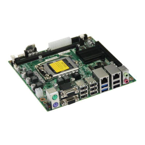
Chapter 1 Product Introduction 1.1Product Introduction MITX-6973 is MINI ITX industrial motherboard based on Intel Skylake-S processor, adopting H110 chipset. It supports Intel Skylake-S processor’s CPU, RS232 mode, WOL, dual sound card design, Line-out, Line-in, and MIC-in. 2 standard DB9 serial ports, 2 standard 7Pin SATA interfaces, 2 standard DB15 VGA interfaces, one 2x10 2.0mm HDM pin, 2xRJ45 network... - Page 11 MITX-6973 User Manual ●Rate:10/100/1000Mbps self-adaption ●2 standard RJ45 network interface ●Support wake on LAN Storage ●Provide 2 standard 7Pin SATA interfaces AUDIO ●Adopts ALC662+ALC662 audio control chip,stereo ●Interfaces:AUDIO1 provides two single sockets(Green one represents Line-out,Pink one is Mic-in), one 2X5Pin 2.0mm pin(Expand Mic,Line-in,Line-out) ,one 2X5Pin 2.0mm pin is AUDIO2 ●I/O chip:F81866...
- Page 12 MITX-6973 User Manual ●BIOS:AMI EFI Operating Temperature ●Operating Temperature: 0℃~60℃ ●Storage Temperature:-40℃~85℃ ●Operating Humidity: 5%~95%, non-condensing ●Storage Humidity: 5%~95%, non-condensing...
- Page 13 Chapter 2 Hardware Functions...
-
Page 14: Chapter Two Hardware Functions
MITX-6973 User Manual Chapter Two Hardware Functions 2.1 Interfaces Location & Dimension Following picture illustrates the interfaces location and dimension of board MITX-6973. Please take care of some components during the installation. Improper installation may leads to system failure. Note: In case of any electrostatic damage caused to some components, please wear anti-static gloves to install the motherboard. -
Page 15: Install Memory
MITX-6973 User Manual 2.Install CPU and CPU fan 3. Install Memory 4.Install other expansion cards 4.Connect all signal lines, cables, control panel circuit and power supply unit. 5.Start the computer and complete BIOS Settings. Key components of this motherboard are Integrated circuit and these components could be easily damaged by electrostatic influence. -
Page 16: Jumper Settings
MITX-6973 User Manual 2.4 Jumper Settings Please refer to following instructions to do jumper settings before installing your hardware devices. Remark: How to identify the PIN1 of all jumpers and interfaces: Please observe the word mark on the side of the plug socket, which will be a “1” or bold line or triangular symbol; And please look at the back of PCB, each with a square shape will be the PIN 1;... -
Page 17: Hardware Switch For System Auto Boot Upon Power On(Jat
MITX-6973 User Manual JCC: Setting CLEAR NORMAL Do not clear CMOS when the computer is power on, otherwise, it will cause damage to the motherboard ! 2.4.2 Hardware Switch for System Auto Boot upon Power On(JAT) JAT: Setting Open Disable Auto Boot... -
Page 18: Serial Ports(Com1,Com2, J9
MITX-6973 User Manual of any damage to the motherboard! 2.5.1 Serial Ports(COM1,COM2, J9) Provide 2 个 serial ports , COM1、 COM2 are standard DB9 ports, support RS232 model, one 3Pin COM power supply pin J9,jumper cap connecting 1Pin、2Pin is 5V power,... -
Page 19: Sata Interface(Sata1、Sata2
MITX-6973 User Manual J9: SIGNAL NAME COM_PIN10 +12V 2.5.2 SATA Interface(SATA1、SATA2) Provide 2 standard 7Pin SATA port。 SATA1、SATA2 SATA1、SATA2: SIGNAL NAME... -
Page 20: Usb1415
MITX-6973 User Manual 2.5.3 USB、LAN Ports(USB12_LAN1,USB911_LAN2,USB345,USB678, USB1213,USB1415) provide 14 USB ports, USB12 is double-layer USB3.0 interface; USB911 is double-layer USB2.0 interface;USB345、USB678 is triple-layer USB2.0 interface; USB1213、USB1415 interface is 2×5PinUSB pin. USB345 USB678 USB12_LAN1 USB911_LAN2 USB1213、USB1415 USB1213、USB1415: SIGNAL NAME SIGNAL NAME 管脚... -
Page 21: Keyboard Mouse Interface(Km
MITX-6973 User Manual 2.5.4 Keyboard mouse Interface(KM) Provide a standard double-layer KB/MS keyboard mouse interface。 KM: SIGNAL NAME KM_DATA VCC_KM KM_CLK 2.5.5 Audio Interface(AUDIO,AUDIO2,FP_AUDIO) Use ALC662 audio control chip,green is Line-out,pink is MIC-in. -
Page 22: Display Interface(Vga_Vga,Hdmi
MITX-6973 User Manual AUDIO AUDIO2 FP_AUDIO AUDIO2: SIGNAL NAME SIGNAL NAME MIC1L2 AGND2 MIC1R2 LINE1L2 FRONTR2 LINE1R2 AGND2 FRONTL2 AGND2 FP_AUDIO: SIGNAL NAME SIGNAL NAME MIC2*L AGND MIC2*R LINE-in-L LINE-out-R LINE-in-R AGND LINE-out-L AGND 2.5.6 Display Interface(VGA_VGA,HDMI) Provide 2 standard DB15 VGA port and one 2x10 2.0mm HDMI pin。... - Page 23 MITX-6973 User Manual VGA_VGA HDMI VGA: SIGNAL NMAE SIGNAL NMAE SIGNAL NMAE VGA_R VGA_G VGA_B HSYNC VSYNC VGA_PIN5 HDMI: SIGNAL NMAE SIGNAL NMAE DATA0_P_R CLK_P_R DATA0_N_R CLK_N_R DATA1_P_R DATA1_N_R DATA2_P_R DETECT DATA2_N_R...
-
Page 24: Jgp
MITX-6973 User Manual HP DET 2.5.7 JGP JGP: SIGNAL NAME SIGNAL NAME GP50 GP51 GP54 GP52 GP55 GP53 GP56 GP57 , ) 2.5.8 Power Interface( J12V Standard ATX 20Pin + 4Pin power supply. - Page 25 MITX-6973 User Manual J12V PWR: SIGNAL NAME SIGNAL NAME +3.3V +3.3V -12V +3.3V PS-ON PW-OK +5VSB +12V J12V: SIGNAL NAME...
-
Page 26: Fan Interface(Cpufan
MITX-6973 User Manual +12V +12V 2.5.9 Fan Interface(CPUFAN) Board provides one 4Pin CPU fan interface,Please pay attention to following points when using this interface: (1)FAN Current ≤500mA(6W, 12V) (2) Please confirm if the FAN cable matches the socket cable. CPU_FAN CPUFAN:... -
Page 27: Getronics (Lpt)
MITX-6973 User Manual 2.5.10 Getronics (LPT) Board provides one 2X10Pin centronics,needs tie line transfer as centronics when using LPT: SIGNALA NAME SIGNALA NAME LPT_STB# LPT_AFD# LPT_PDQ0 LPT_ERR# LPT_PDQ1 LPT_INIT# LPT_PDQ2 LPT_SLIN# LPT_PDQ3 LPT_PDQ4 LPT_PDQ5 LPT_PDQ6 LPT_BUSY LPT_PDQ7 LPT_PE LPT_ACK# LPT_SLCT... -
Page 28: Lpc Bus Interface(Jlpc
MITX-6973 User Manual 2.5.11 LPC Bus Interface(JLPC) Support TPM function. Support AFC-385C expansion serial ports up to 10. JLPC JLPC: SIGNAL NAME SIGNAL NAME LPC_CLK_KZ L_FRAME_N CLK_LPC_48M_KZ PCL_LPC_RST L_AD3 L_AD2 VCC3 L_AD1 L_AD0 SMB_CLK_MAIN SMB_DATA_MAIN 3VDUAL SER_IRQ LPCPD_N L_DRQ1_N RSTBTN... -
Page 29: Power And System Indicator(Led
MITX-6973 User Manual 2.5.12 Power and System Indicator(LED) Note:the upper one indicates HDD, below one is power LED. 2.5.12 Front Panel Connector(JFP) JFP is used to connect function buttons and LED indicator on the front panel. - Page 30 MITX-6973 User Manual JFP: SIGNAL NAME SIGNAL NAME HDD_LED+ HDD_LED- SPK+ SPK- RSTBTN+ POWERSW Please follow the table below to connect, pay attention to the anode (+) and cathode (-), otherwise some function cannot be realized. PWR-LED HDD-LED BUZZ RESET BUTTON POWER BUTTON 1)...
-
Page 31: Dimm Slot(Dimm
MITX-6973 User Manual 2) HDD LED Pins(Pin 3/4 for HDD LED) Case panel comes with one HD LED indicating HD status. When HD read and write, the LED will flash, indicating the device is working. Connect the LED cable to the LED pins ( Pin3 is LED anode). -
Page 32: Chapter 3 Bios Setup
Chapter 3. BIOS SETUP... -
Page 33: Ami Bios Flash
MITX-6973 User Manual Chapter 3 BIOS SETUP AMI BIOS Flash BIOS functions as a bridge connecting hardware and operating system. Hardware and software are upgrading all the time, so when your system goes wrong, for example, your system can not support the newest CPU, you need to upgrade BIOS to keep up with the latest technology. -
Page 34: Bios Setting
MITX-6973 User Manual BIOS Setting 1. Power on or restart the system, self-detection message will display on the screen. 2. When system pops out the prompt "Press <Del> to enter setup" , please press <Del> key to enter BIOS setup interface. -
Page 35: Advanced
MITX-6973 User Manual :ME firmware version ME FW Version :Information of ME’s SKU ME Firmware SKU System Date System Date Format: Month/Day/Year. Setting scale is Month(Jan.-Dec.), Date(01-31), Year(up to 2099), Week(Mon.~Sun.). System Time System Time Format: Hour/Minute/Second. Setting scale is Hour(00-23), Minute(00-59), Second(00-59). -
Page 36: Hardware Monitor
MITX-6973 User Manual Super IO configuration, includes COM interrupt number and address setting Hardware Monitor System monitor, hardware monitoring S5 RTC Wake Settings WakeOnLAN setting Serial Port Console Redirection Serial port console redirection CPU Configuration CPU configuration and common setting SATA Configuration HDD mode setting and HDD information。... - Page 37 MITX-6973 User Manual 3.2.1 ACPI Settings Enable ACPI Auto Configuration This is ACPI auto configuration.(Enabled)or(Disabled)BIOS’s ACPI auto configuration. Default is (Enabled). Enable Hibernation Hibernation supported.(Enabled)or(Disabled)system hibernation function(OS/S4 hibernation status). This option might not be in effect under some OS. Default is (Enabled).
- Page 38 MITX-6973 User Manual 3.2.2 Supper IO Configuration Parallel Port Configuration Setting for centronics.. Serial Port 1 Configuration Setting option for serial port 1. Serial Port 2 Configuration Setting option for serial port 2.
- Page 39 MITX-6973 User Manual Serial Port 1 Configuration 1)Parallel Port Enable or disable the parallel port. Set value: [Enabled][Disabled]. 2)Device Setting(read-only) Display centronics’s occupied IRQ and address 3)Change Setting To alter centronics resource setting, recommend default Auto. 4)Device Mode To set working mode of parallel, incudes standard,EPP+SPP,ECP,ECP+EPP, and etc.
- Page 40 MITX-6973 User Manual Serial Port 1 Configuration 1)Serial Port To enable or disable serial port, set value is [Enabled] [Disabled]。 2)Device Setting(Read-only) Display centronics’s occupied IRQ and address 3)Change Setting To alter centronics resource setting, recommend default Auto. The following serial Port 2 Configuration is as above.
- Page 41 MITX-6973 User Manual...
- Page 42 MITX-6973 User Manual 3.2.3 Hardware Monitor Hardware safety detection PC Health Status Hardware safety detection: it displays current system temperature, CPU temperature, fan speed and other voltage value. All the parameters has a certain scale, and the operation of system cannot exceed the scale.
- Page 43 MITX-6973 User Manual 3.2.4 S5 RTC Wake Settings Wake system from S5 Set up to boot at a certain time or not. Default is [Disabled];Setting up [Fixed Time] means to boot at a certain time. Setting up [Dynamic Time] means to boot at a certain time from this...
- Page 44 MITX-6973 User Manual 3.2.5 Serial Port Console Redirection Console Reditection: Motherboard supports serial ports1, 2 console redirection, default Disable. Enable console redirection just need to turn on COM1 or COM2 console redirection. EMS console redirection is no need to be on.
- Page 45 MITX-6973 User Manual Terminal Type: Terminal type: VT100/VT100+/ VT-UTF8/ANSI. If unreadable codes need to be adjusted by terminal type, default is VT100+. Bits per Second Default 115200. Data Bits Parity Stop Bits Flow Control VT-UTFB Combo Key Support Legacy os Redirection Resolution...
- Page 46 MITX-6973 User Manual...
-
Page 47: Cpu Configuration
MITX-6973 User Manual 3.2.6 CPU Configuration... - Page 48 MITX-6973 User Manual Read only includes detail information of CPU supplier, model, and caches information. Hyper-Threading To set whether using CPU’s hyper-threading technology or not. Set value is [Enabled][Disabled]. Active Processor Cores To adjust Processor Cores ( When using multi-core processor) Can turn off number of cores to improve GHz.
-
Page 49: Sata Configuration
MITX-6973 User Manual Debug Interface Lock SW Guard Extensions(SGX) 3.2.7 SATA Configuration Serial-ATA Controller(S) Disable or Enable SATA Controller. Setting value: [Disabled] [Enabled] SATA Mode selection To setup SATA Mode: [AHCI] or [IDE]. SATA Test Mode [Disabled] Serial ATA Port 0/1/2/3/4/5... -
Page 50: Network Stack Configuration
MITX-6973 User Manual 3.2.8 Network Stack Configuration Network Stack To boot built-in lan in advance under UEFI model. Ipv4 PXE Support Support IPV4 to boot Ipv6 PXE Support Support IPV6 to boot PXE boot wait time Midia detect count... -
Page 51: Csm Configuration
MITX-6973 User Manual 3.2.9 CSM Configuration CSM Support CSM is Compatibity Support Module, belonging to UEFI. Provide compatibility support for those not support UEFI system. GateA20 Active Option ROM Messages To set OpROM display model. INT19 Trap Response [Immediate], [Postponed]... -
Page 52: Usb Configuration
MITX-6973 User Manual Video Choose to support which type of display OpROM,like Efi OpROM or Legacy OpROM, support both. Other PCI devices Other PCI devices OpROM implantation strategy. 3.2.10 USB Configuration Legacy USB Support Legacy USB supports setting. To support USB devices in DOS mode, such as USB FLASH disk, USB keyboard, select this option as [Enabled] or [Auto]. -
Page 53: Chipset Menu
MITX-6973 User Manual To control USB 64/60 emulation. Once emulation is applied, USB keyboard can have some special alternatives. Set value:Disabled,Enabled. USB Transfer time-out Set USB device transfer command, data and time-out (default 20 seconds). Device reset time-out Set USB Devices reset time-out (default 20 seconds). -
Page 54: Pch-Io Configuration
MITX-6973 User Manual PCH-IO Configuration South Bridge configuration information includes sound card, LAN card, and auto boot when power is on. 3.3.1 System Agent (SA) Configuration VT-d Intel I/O virtualization technology, it needs chipset support (support some chipset, but not all). - Page 55 MITX-6973 User Manual Primary Display 此 To show output main display device when the system boots. Primary PEG To choose PEG as primary PEG device. Primary PCIE To choose PCIE as primary PEG device. Internal Graphic To disable built-in video card.
- Page 56 MITX-6973 User Manual Primary IGFX Boot Display To set onboard primary display device.
- Page 57 MITX-6973 User Manual 3.3.2 PCH-IO Configuration USB configuration HD Audio Enable or disable the onboard sound card. LAN1/2 Controller Enable or disable the onboard LAN controller. Restore AC Power Loss Select the computer starting up status after restoring the AC power.
- Page 58 MITX-6973 User Manual USB Precondition To set USB precondition: Disabled(default),Enabled XHCI Disable Compliance Mode Disable compatibility model of XHCI: FALSE(default),TRUE xDCI support To set USB OTG support function, Disabled(default),Enabled USB Port Disable Override To set disable USB port.
-
Page 59: Boot Menu
MITX-6973 User Manual 3.4 Boot Menu Setup Prompt Timeout Number of seconds to wait for setup activation key. If not press setup activation key within the preset time slot, system will continue starting up. Bootup Numlock State This function allows users to activate Numlock function when boot up. - Page 60 MITX-6973 User Manual Hard Drive BBS Priorities This option contains HDDs that can be used as boot device. If multiple HDDs in this option, priority should set for these HDDs, then the prior one will show in Boot Option #1 as the...
-
Page 61: Security Menu
MITX-6973 User Manual 3.5 Security Menu Password should within the following length: Mininum:1. Maxium:20. Administrator Password Set administrator password. User Password Set User’s Password. -
Page 62: Save&Exit Menu
MITX-6973 User Manual 3.6 Save&Exit Menu Save Changes and Exit Save all BIOS changes and exit, and continue reboot. Discard Changes and Exit Discard all changes and exit, and continue reboot. Save Changes and Reset Save all BIOS changes and exit, then reboot... -
Page 63: Appendix
Appendix... -
Page 64: Appendix:watchdog Programming Guide
MITX-6973 User Manual Appendix Appendix:Watchdog Programming Guide watchdog reference code(C) ----------------------------------------------------------------------------------------------------------------------------- Set the port to realize watchdog function through DEBUG order, so that it can carry out Watchdog Timer’s various functions. Port Instructions: void main() int indexp = 0x2e,datap = 0x2f;... -
Page 65: Appendix 2: Glossary
MITX-6973 User Manual Appendix 2: Glossary ACPI Advanced Configuration and Power Management. ACPI specifications allow operating system to control most power of the computer and its add-ons. Windows 98/98SE,Windows 2000 and Windows ME supports this specification. BIOS Basic input/output system. It is a kind of software including all in/out control code interface in PC. - Page 66 MITX-6973 User Manual memory bus width. DRAM Dynamic Random Access Memorizer. It’s a normal type of memory often with a transistor and a capacitance to store 1 bit. With the development of the technology, more and more types of DRAM with different specifications exist in computer applications. For example: SDRAM/DDR SDRAM/RDRAM.
-
Page 67: Appendix 3: Install Driver
Appendix 3: Install Driver Please install the driver as the following steps: Insert the programmed disk into CD-ROM, “Norco Drivers Installer” will pop up. Find the parallel motherboard name, and click enter device driver interface. Find the device driver list parallel to the system, click driver respectively to install.
Need help?
Do you have a question about the MITX-6973 and is the answer not in the manual?
Questions and answers