Table of Contents
Advertisement
Quick Links
Advertisement
Table of Contents

Related Manuals for Norco MITX-6922


Summary of Contents for Norco MITX-6922
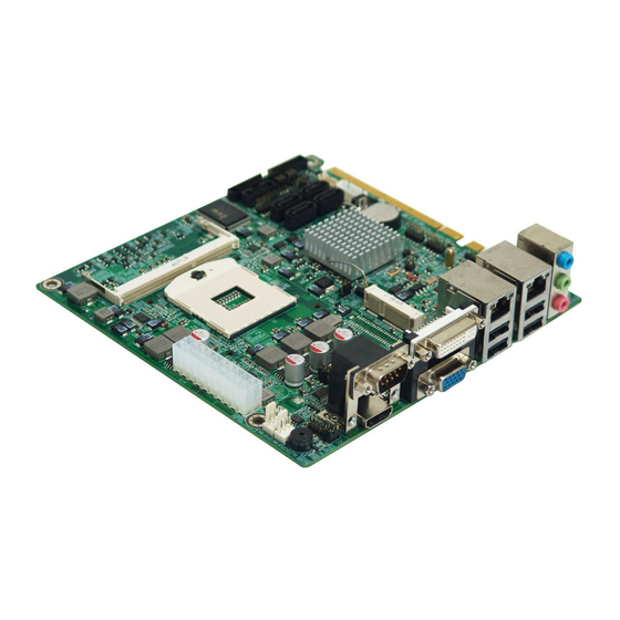
- Page 1 MITX-6922 Mini-ITX Motherboard User Manual V2.1...
- Page 2 Before ordering products, please learn about the product performance from the distributors to see if it is in line with your needs. NORCO is a registered trademark of Shenzhen NORCO Intelligent Technology CO., LTD. The ownership of other trademarks involved in this manual is owned by its respective owners.
- Page 3 Safety Instructions 1. Please read the product manual carefully before using this product. 2.Put all the unused or uninstalled boards or electronic components in a static dissipative surface or static shielding bag. 3.Always ground yourself to remove any static discharge before touching the board, to place your hands on grounding metal object for a while or wear a anti-static wrist strap at all times.
-
Page 4: Table Of Contents
Content Chapter One Product Introduction ................... 1 1.1 Introduction ......................... 1 1.2 Product Specification ....................1 Chapter Two Installation ......................4 2.1 Port Position and Dimension Figure ................4 2.2 Installation Steps ......................4 2.3 Memory Installation ..................... 5 2.4 Jumper Setting ......................5 2.4.1 CMOS Remove/keep Settings(JCC)... - Page 5 AMI BIOS Describtion ..................... 25 BIOS Setting: ....................... 26 3.1 Main Menu ....................... 26 3.2 Advanced Menu ....................... 27 3.2.1 APM Configuration ..................27 3.2.2 ACPI Settings ....................28 3.2.3 CPU Configuration ..................29 3.2.4 SATA Configuration ..................31 3.2.5 AMT Configuration ..................31 3.2.6 USB Configuration ..................
-
Page 6: Chapter One Product Introduction
Chapter One Product Introduction... -
Page 7: Introduction
Chapter One Product Introduction 1.1 Introduction MITX-6922 is a Mini-ITX motherboard which applies Intel QM77/HM77 chipset. The product supports Intel Socket G2 Mobile Sandy/Ivy Bridge i7/i5/i3 processor, dual-channel SO-DIMM memory slot, DDRⅢ1066/1333/1600, and memory up to 8 GB. It has 4x SATA port, 2x Ethernet port, VGA, DVI, LVDS display interfaces. - Page 8 MITX-6922 Intel QM67/QM77 Chipset Based Mini-ITX Motherboard Storage ●4x standard 7 Pin SATA port, and SATA1,SATA2 suport SATA 3.0。Supports AMT8.0. LAN Function ●Network controller: applies Intel 82579LM/82583V network chip ●2x standard RJ45 port ● Supports Wake on LAN(WOL) ● Rate:10/100/1000Mbps Audio Interface ●Applies ALC662HD audio control chip...
- Page 9 MITX-6922 Intel QM67/QM77 Chipset Based Mini-ITX Motherboard Power Support ●Applies DC 12V single power supply Watchdog ●Supports hardware reset function BIOS ●8MB SPI BIOS Environment ●Operating Temperature:0℃~60℃ ●Storage Temperature:-40℃~85℃ ●Operating Humidity:5%~95%, non-condensing...
- Page 10 Chaper Two Installation 明...
-
Page 11: Chapter Two Installation
Chapter Two Installation 2.1 Port Position and Dimension Figure Below is MITX-6922 front panel port position and size diagram. Please be careful when you install the device, and false installation may cause malfunction. Note: In case of any electrostatic damage caused to some components, please wear anti-static gloves to install the motherboard. -
Page 12: Memory Installation
MITX-6922 Intel QM67/QM77 Chipset Based Mini-ITX Motherboard 2.Install memory. 3.Install other expansion cards. 4.Connect all signal line, cable, panel control wiring, and power supply. 5.Turn on computer, and finish BIOS program setting. Key components of this motherboard are Integrated circuit and these components could be easily damaged by electrostatic influence. -
Page 13: Hardware Switch For System Auto Boot Upon Power On(Jat
MITX-6922 Intel QM67/QM77 Chipset Based Mini-ITX Motherboard (1)Turn off the computer, disconnect power supply; (2)Use jumper Cap JCC Pin1and 2 connect for 5~10 seconds, then restore 2-3; (3)Press “F9”---“Enter” and reload optimal default value; (4)Press F10 save and exit. JCC:... -
Page 14: Me Settings(Jcm
MITX-6922 Intel QM67/QM77 Chipset Based Mini-ITX Motherboard 2.4.3 ME Settings(JCM) JCM:... -
Page 15: Com3 Jumper Settings(J5,J6,J8
MITX-6922 Intel QM67/QM77 Chipset Based Mini-ITX Motherboard Setting Clear ME settings Normal working status, default setting 2.4.4 COM3 Jumper Settings(J5,J6,J8) J5, J6, J8 jumpers are used to set COM3 transmission mode, COM3 supports RS 232/RS 422/RS 485 three modes, you can set it according to your requirement, and the default mode is RS 232. -
Page 16: Sata Port(Sata1,Sata2,Hdd_Power
MITX-6922 Intel QM67/QM77 Chipset Based Mini-ITX Motherboard 2.5.1 SATA Port(SATA1,SATA2,HDD_POWER) Provides 2x SATA port, 1x 5Pin hardware power interface. SATA1-SATA4 HDD_POWER SATA: Signal Name JSATAPWR: Signal Name +3.3V +12V... -
Page 17: Serial Port(Com1,Com2, Com3-6
MITX-6922 Intel QM67/QM77 Chipset Based Mini-ITX Motherboard 2.5.2 Serial Port(COM1,COM2, COM3-6) Provides 6x serial port, COM1, COM2 are standard DB9 socket; COM3-COM6 are 2× 20Pin, a tieline is needed to connect the device. You can turn on or turn off serial ports on BIOS settings, and select its interrupt IRQ and I/Q address. - Page 18 MITX-6922 Intel QM67/QM77 Chipset Based Mini-ITX Motherboard COM3-COM6: Signal Name Signal Name HDCD#3 HDSR#3 HSIN3 HRTS#3 HSOUT3 HCTS#3 HDTR#3 HRI#3_3 HDCD#4 HDSR#4 HSIN4 HRTS#4 HSOUT HCTS#4 HDTR#4 HRI#4_4 HDCD#5 HDSR#5 HSIN5 HRTS#5 HSOUT5 HCTS#5 HDTR#5 HRI#5_5 HDCD#6 HDSR#6 HSIN6 HRTS#6...
-
Page 19: Display Port(Vga, Dvi,Lvds
MITX-6922 Intel QM67/QM77 Chipset Based Mini-ITX Motherboard 2.5.3 Display Interface(VGA, DVI,LVDS) VGA、DVI LVDS VGA: Signal Name Signal Name Signal Name GREEN BLUE HSYNC VSYNC DDCCLK DVI: Signal Name Signal Name DATA2- DATA2+ DATA4- DATA4+ DDC CLOCK... - Page 20 MITX-6922 Intel QM67/QM77 Chipset Based Mini-ITX Motherboard DDC DATA DATA1- DATA1+ DATA3- DATA3+ HOT PLUG DETECT DATA0- DATA0+ CLOCK+ CLOCK- LVDS: Signal Name Signal Name VDD_PANEL VDD_PANEL 管脚 VDD_PANEL LVDSA_DATA0# LVDSA_DATA0 LVDSA_DATA1# LVDSA_DATA1 LVDSA_DATA2# LVDSA_DATA2 LVDSA_CLK# LVDSA_CLK LVDSA_DATA3# LVDSA_DATA3 LVDSB_DATA0#...
-
Page 21: Lvds Supply Voltage(Lvds_Bklt
MITX-6922 Intel QM67/QM77 Chipset Based Mini-ITX Motherboard 2.5.4 LVDS Supply Voltage(LVDS_BKLT) LVDS_BKLI LVDS_BKLT: Signal Name BKLT_CTRT BKLT_EN +12V 2.5.5 USB Ports(USB_12,USB_34,USB56_LAN1,USB78_LAN2) External USB port and network port, two independent sockets. Separately provides 2 standard USBs and one standard RJ45 port. USB_12, USB_34 are internal USB port, two 2×... - Page 22 MITX-6922 Intel QM67/QM77 Chipset Based Mini-ITX Motherboard USB56_LAN1 USB78_LAN2 USB_12 USB_34 Standard USB port: Signal Name USB DATA- USB DATA+ USB_12,USB_34: Signal Name Signal Name USB DATA- USB DATA+ USB DATA+ USB DATA-...
-
Page 23: Keyboard, Mouse Port(Kbms
MITX-6922 Intel QM67/QM77 Chipset Based Mini-ITX Motherboard 2.5.6 Keyboard and Mouse Port(KBMS) Provide one keyboard and mouse port KBMS KBMS: Signal Name Signal Name KB_DATA VCC_KM KB_CLK MS_DATA VCC_KM MS_CLK... -
Page 24: Jgpio1
MITX-6922 Intel QM67/QM77 Chipset Based Mini-ITX Motherboard 2.5.7 JGPIO1 Provides one 2×10Pin JGPIO1 JGPIO1 JGPIO1: Signal Name Signal Name IO_00 IO_01 IO_04 IO_02 IO_05 IO_03 IO_06 IO_07... -
Page 25: Ports(Jcan
MITX-6922 Intel QM67/QM77 Chipset Based Mini-ITX Motherboard 2.5.8 Ports(JCAN) JCAN JCAN: Signal Name CANR CANL... -
Page 26: Power Interface(Pwr
MITX-6922 Intel QM67/QM77 Chipset Based Mini-ITX Motherboard 2.5.9 Power Interface(PWR) PWR: Signal Name +12V +12V 2.5.10 Fan Interface (CPUFAN,SYSFAN) Provides 1x 4Pin CPU fan interface and 1x 3Pin system fan interface. (1)FAN Current ≤350mA(4.2W, 12V). (2) Please confirm if the FAN cable matches the socket cable. -
Page 27: Audio Interface(Audio
MITX-6922 Intel QM67/QM77 Chipset Based Mini-ITX Motherboard CPUFAN SYSFAN CUFAN: Signal Name +12V Speed detect Speed control SYSFAN: Signal Name +12V Speed detect 2.5.11 Audio Interface (Audio) Provides 1x Audio port, and the blue one is Line-in, the green one is speaker, the red one is... -
Page 28: Front Panel Interface(Jfp
MITX-6922 Intel QM67/QM77 Chipset Based Mini-ITX Motherboard AUDIO 2.5.12 Front Panel Port (JFP) Front panel pin, connects function button and indicator LED in the front of the chassis, and one 2×5Pin pin. - Page 29 MITX-6922 Intel QM67/QM77 Chipset Based Mini-ITX Motherboard JFP: Signal Name Signal Name PLED+ HDD_LED+ HDD_LED- BUZZDATA# FP_RESET_BT POWERSW#_R Please connect following chart below, and pay attention to the anode (+) and cathode (-). If it is falsely connected, it may not function well.
-
Page 30: Memory Slot(Dimm
MITX-6922 Intel QM67/QM77 Chipset Based Mini-ITX Motherboard power on, power LED is on;when system is power off, power LED is off. 2)HDD LED Pin (pin 3, pin 4 HDD LED) Chassis panel comes with one HDD LED indicating HD status. When HD reads and writes, the LED will flash, indicating the device is working. - Page 31 Chapter Three BIOS Setup...
-
Page 32: Chapter Three Bios Program Setting
MITX-6922 Intel QM67/QM77 Chipset Based Mini-ITX Motherboard Chapter Three BIOS Setup AMI BIOS Refresh BIOS function is a bridge connecting hardware and operating system. Hardware and software are upgrading all the time, so when your system goes wrong, for example, your system does not support the newest CPU, you need to upgrade BIOS to keep up with the latest technology. -
Page 33: Bios Setting
MITX-6922 Intel QM67/QM77 Chipset Based Mini-ITX Motherboard BIOS Setting: After the computer turned on, and finished self-diagnosis, information below will display on the screen: Del->SETUP, then click on Del button, and BIOS will turn to SETUP configuration screen after its detecting to IDE and other devices. -
Page 34: Advanced Menu
MITX-6922 Intel QM67/QM77 Chipset Based Mini-ITX Motherboard System Time System Time Format: Hour/Minute/Second. 3.2 Advanced Menu BIOS SETUP UTILITY Enabled or Disabled Boot Option BIOS Information for Legacy Netword Devices. Launch LAN1 PXE OpROM [Disabled] Launch LAN2 PXE OpROM [Disabled] →←:Select Screen... -
Page 35: Acpi Settings
MITX-6922 Intel QM67/QM77 Chipset Based Mini-ITX Motherboard Enable or disable System wake on RTC Power On Function [Enabled] alarm event. When enabled. RTC Power On Hour System will wake RTC Power On Minute hr::min::sec specified RTC Power On Second →←:Select Screen ↑↓:Select Item... -
Page 36: Cpu Configuration
MITX-6922 Intel QM67/QM77 Chipset Based Mini-ITX Motherboard →←:Select Screen ↑↓:Select Item Enter:Select +/-:Change Opt. F1:General Help F9:Optimized Defaults F10:Save&Exit ESC:Exit Version 2.10.1208. Copyright(C)2010 American Megatrends,Inc. ACPI Sleep State Select power-saving mode when system sleeps, and different modes have different consumption. S1(pos):CPU stops working, but other devices still work; S3(STR): Suspend to RAM. - Page 37 MITX-6922 Intel QM67/QM77 Chipset Based Mini-ITX Motherboard Intel Virtualization Technology [Enabled] EIST [Disabled] CPU C3 Report [Disabled] CPU C6 report [Disabled] CPU C7 report [Disabled] Version 2.10.1208. Copyright(C)2010 American Megatrends,Inc. Read-only option contains CPU detailed information, including CPU maker, model, frequency, size of level 1 cache, size of level two cache.
-
Page 38: Sata Configuration
MITX-6922 Intel QM67/QM77 Chipset Based Mini-ITX Motherboard systems on one machine at same time. One processor operates one OS, and another processor operates another OS. EIST Turn on and off Enhanced Intel SpeedStep Technology CPU C state Report Turn on CPU power status report, and the set values are: [Disabled],[Enabled]. - Page 39 MITX-6922 Intel QM67/QM77 Chipset Based Mini-ITX Motherboard Un-Configure ME [Disabled] Note: iAMT always End of Post Enable [Enabled] enabled. This option just controls the BIOS extension execution. If enabled, this requires additional firmware in the SPI device. →←:Select Screen ↑↓:Select Item Enter:Select...
-
Page 40: Usb Configuration
MITX-6922 Intel QM67/QM77 Chipset Based Mini-ITX Motherboard 3.2.6 USB Configuration BIOS SETUP UTILITY Enable or Disable the USB EHCI USB Configuration (USB 2.0) functions. USB Devices : One EHCI controller must always 1 Drive , 2 Hubs be enabled. →←:Select Screen... -
Page 41: It8783F H/W Monitor
MITX-6922 Intel QM67/QM77 Chipset Based Mini-ITX Motherboard Set Parameters of Serial Port 1 IT8783F Super IO Configuration (COMA) IT8783F Super IO Chip IT8783F Serial Port 1 Configuration Serial Port 2 Configuration →←:Select Screen Serial Port 3 Configuration ↑↓:Select Item Serial Port 4 Configuration Enter:Select... -
Page 42: Serial Port Console Redirection
MITX-6922 Intel QM67/QM77 Chipset Based Mini-ITX Motherboard →←:Select Screen CPU Temperature : +43℃ ↑↓:Select Item SYS Temperature : + 36℃ Enter:Select CPU Fan Speed : 5357 RPM +/-:Change Opt. SYS Fan Speed : N/A F1:General Help F9:Optimized Defaults CPUVCORE : +1.061V F10:Save&Exit... -
Page 43: Chipset Menu
MITX-6922 Intel QM67/QM77 Chipset Based Mini-ITX Motherboard →←:Select Screen ↑↓:Select Item COM2 Console Redirection [Disabled] Enter:Select Console Redirection Settings +/-:Change Opt. F1:General Help Serial Port for Out-of-Band Management/ F9:Optimized Defaults Windows Emergency Management F10:Save&Exit Services(EMS) ESC:Exit Console Redirection [Disabled] Console Redirection Settings Version 2.10.1208. -
Page 44: North Bridge
MITX-6922 Intel QM67/QM77 Chipset Based Mini-ITX Motherboard 3.3.1 North Bridge BIOS SETUP UTILITY Enable PEG [Enabled] To enable or disable the PEG. Primary Display [Auto] →←:Select Screen DVMT Pre-Allocated [64M] ↑↓:Select Item DVMT Total Gfx Mem [MAX] Enter:Select +/-:Change Opt. -
Page 45: South Bridge
MITX-6922 Intel QM67/QM77 Chipset Based Mini-ITX Motherboard Active LFP Turn on/off LVDS display. LCD Panel Type Set resolution on LVDS display mode. Panel Color Depth Set color depth on LVDS display mode. Flat Panel Backlight Set brightness on LVDS display mode. -
Page 46: Boot Menu
MITX-6922 Intel QM67/QM77 Chipset Based Mini-ITX Motherboard Wake on LAN Turn on and off network Wake on LAN, and set values are [Enabled][Disabled]. Restore AC Power Loss Set how to turn on computer after power on. If Power Off is selected then the you need to press power button to turn on the computer;... -
Page 47: Security Menu
MITX-6922 Intel QM67/QM77 Chipset Based Mini-ITX Motherboard Show Full Logo Show vender logo on startup screen. [Enabled]: shows static LOGO when computer is turned on, and [Disabled]: shows self-test information when computer is turned on. Boot Option #1 System will test devices according to the order set until a device is detected can be turned on, and turn on the device. -
Page 48: Save & Exit Menu
MITX-6922 Intel QM67/QM77 Chipset Based Mini-ITX Motherboard Show if user password is set, if it is set, then “Install” will be displayed, or “Nor Installed” will be displayed. 3.6 Save & Exit Menu BIOS SETUP UTILITY Load Defaults Restore/Load Default values for all Save Changes and Exit the setup options. -
Page 49: Appendix
Appendix... - Page 50 MITX-6922 Intel QM67/QM77 Chipset Based Mini-ITX Motherboard Appendix 附一: Watchdog Programming Guide watchdog reference code(ASM) -------------------------------------------------------------------------------------------------------------- Set the port to realize watchdog function through writing data of ports with the programming C language to carry out Watchdog Timer’s various functions.
- Page 51 MITX-6922 Intel QM67/QM77 Chipset Based Mini-ITX Motherboard outportb(indexp,0x02); temp = (unsigned char)inportb(datap); temp |= 0x02; outportb(datap,temp); //lock...
-
Page 52: Appendix2:Glossary
MITX-6922 Intel QM67/QM77 Chipset Based Mini-ITX Motherboard Appendix2:Glossary ACPI Advanced Configuration and Power Management. ACPI specifications allow operating system to control most power of the computer and its add-ons. Windows 98/98SE,Windows 2000 and Windows ME supports this specification. BIOS Basic input/output system. It is software including all in/out control code interface in PC. - Page 53 MITX-6922 Intel QM67/QM77 Chipset Based Mini-ITX Motherboard applications. For example: SDRAM/DDR SDRAM/RDRAM. Network interface. Network grouped by correlative computers in a small area, generally in a company or a building. Local area network is buildup by sever, workstation, some communications links. Terminals can access data and devices anywhere through cables, which enables users to share costly devices and resource.
Need help?
Do you have a question about the MITX-6922 and is the answer not in the manual?
Questions and answers