Table of Contents
Advertisement
Quick Links
Advertisement
Table of Contents

Related Manuals for Norco MITX-6934


Summary of Contents for Norco MITX-6934
- Page 1 MITX-6934 Mini-ITX Motherboard User Manual V1.0...
- Page 2 Before ordering products, please learn about the product performance from the distributors to see if it is in line with your needs. NORCO is a registered trademark of Shenzhen NORCO Intelligent Technology CO.,LTD. The ownership of other trademarks involved in this manual is owned by its respective owners.
-
Page 3: Safety Instruction
Safety Instruction 1. Please read this manual carefully before using this product. 2. Please put all unused/uninstalled boards and cards in the anti-static bags. 3. Please first place your hands on grounding metal objects for a while before you go to take out the board from its package, so as to release the static electricity of your body. -
Page 4: Table Of Contents
Content Chapter 1 Product Introduction......................1 1.1 Overview ...........................1 1.2 Product Specification ......................1 Chapter 2 Installation Instructions ....................3 2.1 Interfaces Location and Dimension..................3 2.2 Installation Steps.......................4 2.3 Install DIMM ........................4 2.4 Jumper Settings ........................4 2.4.1CMOS Clear/Hold Jumper Setting(JCC) ............4 2.4.2 Hardware Switch for System Auto Boot upon Power On(JAT)......6 2.4.3 J_WDOG Setting ....................6 2.5 Interfaces Description.......................7 2.5.1 SATA Interface(SATA)... - Page 5 Chapter 3 BIOS SETUP.......................20 AMI BIOS Upgrading ......................20 AMI BIOS Description......................20 BIOS Settings........................20 3.1 Main Menu ........................21 3.2 Advanced Menu ......................22 3.2.1 ACPI Settings .......................22 3.2.2 APM Configuration ....................23 3.2.3 CPU Configuration ....................24 3.2.4 SATA Configuration ....................26 3.2.5 USB Configuration....................27 3.2.6 Supper IO Configuration ..................27 3.2.7 H/W Monitor......................28 3.2.8 Serial Port Console Redirection................29...
-
Page 7: Chapter 1 Product Introduction
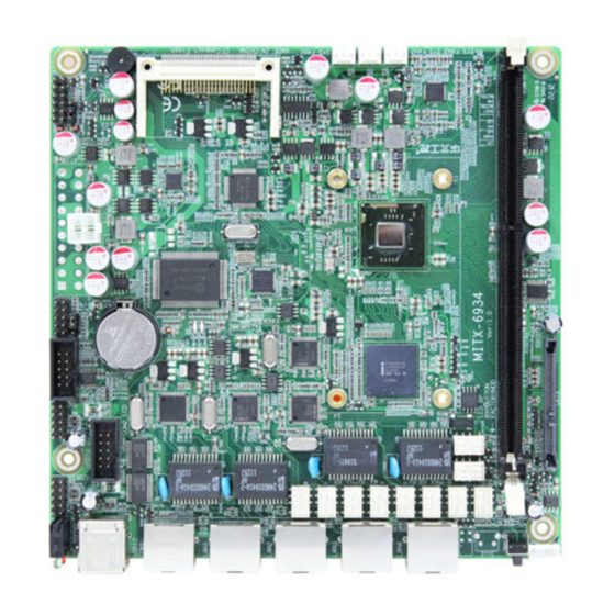
LAN bypass feature allows data to flow through passively instead of terminating at the device. The MITX-6934 also gives you the option to boot directly from a CF card, or from a standard HDD or SSD drive via the SATA II port. In addition to the 2 external, and 4 internal USB 2.0 ports, the I/O on this system includes two serial ports one via RJ45 and the other via... - Page 8 MITX-6934 Intel Cedar Trail Powered 4 Gigabit Mini-ITX Motherboard Memory ●1x single channel U-DIMM slot supports DDRIII 800/1066 RAM upto 4GB. Storage ●1x standard 7+15 Pin SATA port ●LAN Controller: 4x Intel 82583V LAN chip ●4 x standard RJ45 ports, transmission rate up to 10/100/1000Mbps ●...
-
Page 10: Chapter 2 Installation Instructions
2.1 Interfaces Location & Dimension The following picture shows the front panel interfaces location and the dimension of board MITX-6934. Please pay attention to the installation procedures. Improper installation of any components will lead to system malfunction. Note: Please ware anti-static gloves to install the board, so as to avoid static electricity causing any damage to the board. -
Page 11: Installation Steps
MITX-6934 Intel Cedar Trail Powered 4 Gigabit Mini-ITX Motherboard 2.2 Intallation Steps Please follow the steps below to install your computer 1. Adjust all jumpers onboard according to the user manual 2. Install DIMM 3. Install other expansion cards 4. Connect all signal cables, power cable, panel control circuit and power adaptor 5.Start the computer and finish BIOS settings. - Page 12 MITX-6934 Intel Cedar Trail Powered 4 Gigabit Mini-ITX Motherboard of previous system settings and back to the original system setting (factory default). Steps: ( (1)Turn off the computer and disconnect the power supply (2)Use Jumper Cap JCC Pin1-2 short for 5~6 sec. Then restore the default setting with Pin2-3 connected (3)Turn on the computer, then press “DEL”...
-
Page 13: Hardware Switch For System Auto Boot Upon Power On(Jat
MITX-6934 Intel Cedar Trail Powered 4 Gigabit Mini-ITX Motherboard 2.4.2 Hardware Switch for System Auto Boot upon Power On(JAT) JAT: Setting Open Disable the auto boot function Close Enable the auto boot function 2.4.3 J_WDOG Setting To setup WATCHDOG function via J_WDOG setting. -
Page 14: Interfaces Description
MITX-6934 Intel Cedar Trail Powered 4 Gigabit Mini-ITX Motherboard Setting J_WDOG WATCHDOG Note: NC means no watchdog function. 2.5 Interfaces Description Please read the following instructions carefully before you connecting the external connectors in case of any damage caused to the motherboard. -
Page 15: Cf Card Socket(Compact Flash
MITX-6934 Intel Cedar Trail Powered 4 Gigabit Mini-ITX Motherboard SATA: Signal Name Signal Name +12V VCC3 +12V VCC3 +12V VCC3 2.5.2 CF Card Socket(Compact Flash) Board rear panel provides one 50Pin standard CF card socket , supporting TypeⅠ/ⅡCFCard. -
Page 16: Serial Ports(Com1, Com2_Lcd
MITX-6934 Intel Cedar Trail Powered 4 Gigabit Mini-ITX Motherboard 2.5.3 Serial Ports(COM1, COM2_LCD) Board provides 2x serial ports. COM1 is the RJ45 port. COM2_LCD is the 2×5Pin port. COM1-RJ COM2_LCD COM1: Signal Name HRTS#1 HDTR#1 HSOUT1 HSIN1 HDSR#1 HCTS#1 COM2_LCD:... -
Page 17: Display Interface(Vga
MITX-6934 Intel Cedar Trail Powered 4 Gigabit Mini-ITX Motherboard 2.5.4 Display Interface(VGA) VGA: Signal Name Signal Name GREEN BLUE HSYNC VSYNC 2.5.5 USB Ports(USB12, USB34, USB56) Board provides 6x USB ports. USB12 is the standard USB 2.0 port. USB34 , USB56 are the 2... -
Page 18: Network Interface(Lan1, Lan2, Lan3, Lan4
MITX-6934 Intel Cedar Trail Powered 4 Gigabit Mini-ITX Motherboard Standard USB Port: Signal Name USB DATA- USB DATA+ USB_34, USB_5: Signal Name Signal Name USB DATA- USB DATA+ USB DATA+ USB DATA- 2.5.6 Network Interface(LAN1, LAN2, LAN3, LAN4) Board provides 4x Gigabit Ethernet Ports. -
Page 19: Programmable Input/Output Interface(Jgp
MITX-6934 Intel Cedar Trail Powered 4 Gigabit Mini-ITX Motherboard LED Status: LILED(Green/Orange) ACTLED(Yellow) Function Function Green 1000M Link Flash Data Transfer Orange 100M Link Flash Data Transfer Flash Data Transfer No Link No Data 2.5.7 Programmable Input/Output Interface(JGP) General Purpose Input and Output. 8bit GPIO. One 2x5Pin header. -
Page 20: Power Interface(Pwr, Atx
MITX-6934 Intel Cedar Trail Powered 4 Gigabit Mini-ITX Motherboard GPIO: Signal Name Signal Name SIO_GP24 SIO_GP25 SIO_GP20 SIO_GP26 SIO_GP21 SIO_GP27 SIO_GP22 SIO_GP23 2.5.8 Power Interface(PWR, ATX) System supports two power mode. The +12V single power(PWR)and the ATX power(ATX). Single power and ATX power defined as below:... - Page 21 MITX-6934 Intel Cedar Trail Powered 4 Gigabit Mini-ITX Motherboard PWR: Signal Name +12V +12V ATX: Signal Name Signal Name +3.3V +3.3V +3.3V -12V PS-ON PW-OK +5V SB +12V...
-
Page 22: Fan Connector(Sys_Fan1, Sys_Fan2, Sys_Fan3
MITX-6934 Intel Cedar Trail Powered 4 Gigabit Mini-ITX Motherboard 2.5.9 FAN Connector(SYS_FAN1, SYS_FAN2, SYS_FAN3) Board provides 3x SYSFAN. Please pay attention to following remarks: (1) The electric current of the FAN ≤350mA(4.2W, 12V) (2) Please check if the fan cable matches the socket wiring. The power cable is generallythe red one in the middle. -
Page 23: Front Panel Connector(Jfp
MITX-6934 Intel Cedar Trail Powered 4 Gigabit Mini-ITX Motherboard power LED. This LED will on when system is power on. The red LED is the HDD LED. When HDD read/write, the LED is on. PWR LED HDD LED Reset Button... - Page 24 MITX-6934 Intel Cedar Trail Powered 4 Gigabit Mini-ITX Motherboard JFP: Signal Name Signal Name POWER LED+ POWER LED- HD LED+ HD LED- RESET BUTTON POWER BUTTON Please follow the table below to connect, pay attention to the anode(+) and cathode(-).
-
Page 25: Dimm Slot(Dimm
MITX-6934 Intel Cedar Trail Powered 4 Gigabit Mini-ITX Motherboard 1)System Power LED Pins(Pin1-2: PWRLED) Connect system power LED cable with these pins.(pin 1 is LED anode)When system is power on, power LED is on;when system is power off, power LED is off. -
Page 26: Bypass Function Block Diagram
MITX-6934 Intel Cedar Trail Powered 4 Gigabit Mini-ITX Motherboard 2.6.2 BYPASS Function Block Diagram 2.6.3 Setup BYPASS in BIOS & WINDOWS/LINUX To setup BYPASS in BIOS. Details pls refer to the “BYPASS Power ON/ BYPASS Power Off” option in Chipset Menu. - Page 27 MITX-6934 Intel Cedar Trail Powered 4 Gigabit Mini-ITX Motherboard Power Off Bypass: Input“A,1” and press [Enter]; Power Off unbypass: Input“A,0” and press [Enter]; Exit: Input“qt”and press [Enter]...
-
Page 29: Chapter 3 Bios Setup
MITX-6934 Intel Cedar Trail Powered 4 Gigabit Mini-ITX Motherboard Chapter 3 BIOS SETUP AMI BIOS Upgrading It is true that hardware and software are upgrading all the time. When your IPC can not support the newest processor (for example), you should upgrade the BIOS to try to keep up with the latest technology. -
Page 30: Main Menu
MITX-6934 Intel Cedar Trail Powered 4 Gigabit Mini-ITX Motherboard its sub-menu. 4. Use the “←↑→↓” and <Enter> to modify the value of the chosen option, then press” Enter” to modify BIOS options that you choose 5. At any time, press<Esc> can go back to the father-menu. -
Page 31: Advanced Menu
MITX-6934 Intel Cedar Trail Powered 4 Gigabit Mini-ITX Motherboard System Date Format: Week/Month/Day/Year. 3.2 Advanced Menu BIOS SETUP UTILITY Enabled or Disabled Boot Option BIOS Information for Legacy Network Devices. Legacy OpROM Support Launch LAN1 PXE OpROM [Disabled] Launch LAN2 PXE OpROM [Disabled] →←:Select Screen... -
Page 32: Apm Configuration
MITX-6934 Intel Cedar Trail Powered 4 Gigabit Mini-ITX Motherboard →←:Select Screen ↑↓:Select Item Enter:Select +/-:Change Opt. F1:General Help F2:Previous Values F9:Optimized Defaults F10:Save&Exit ESC:Exit Version 2.10.1208. Copyright(C)2010 American Megatrends,Inc. ACPI Sleep State Select the highest ACPI sleep state the system will enter when the suspend button is pressed. -
Page 33: Cpu Configuration
MITX-6934 Intel Cedar Trail Powered 4 Gigabit Mini-ITX Motherboard →←:Select Screen ↑↓:Select Item Enter:Select +/-:Change Opt. F1:General Help F2:Previous Values F9:Optimized Defaults F10:Save&Exit ESC:Exit Version 2.10.1208. Copyright(C)2010 American Megatrends,Inc. RTC Power On Function When Enabled, users can set the date and time at which the RTC (real time clock) alarm awakens the system from Suspend mode. - Page 34 MITX-6934 Intel Cedar Trail Powered 4 Gigabit Mini-ITX Motherboard Limit CPUID Maximum [Disabled] EIST [Disabled] CPU C state Report [Disabled] Version 2.10.1208. Copyright(C)2010 American Megatrends,Inc. The read only option contains detailed information of CPU, including CPU manufacturer, model,frequency, L1 Cache, L2 Cache, etc.
-
Page 35: Sata Configuration
MITX-6934 Intel Cedar Trail Powered 4 Gigabit Mini-ITX Motherboard SpeedStep Technology allows the system to dynamically adjust processor voltage and core frequency, which can result in decreased average power consumption and decreased average heat production. CPU C state Report Enable or disable the CPU C-states. -
Page 36: Usb Configuration
MITX-6934 Intel Cedar Trail Powered 4 Gigabit Mini-ITX Motherboard 3.2.5 USB Configuration BIOS SETUP UTILITY Enable / Disable USB Function. USB Configuration USB Devices: 1 Keyboard ,1 Mouse →←:Select Screen ↑↓:Select Item USB function [Enabled] Enter:Select USB 2.0 (EHCI) Support [Enabled] +/-:Change Opt. -
Page 37: H/W Monitor
MITX-6934 Intel Cedar Trail Powered 4 Gigabit Mini-ITX Motherboard Serial Port 1 Configuration (COMA) Serial Port 2 Configuration →←:Select Screen ↑↓:Select Item Enter:Select +/-:Change Opt. F1:General Help F2:Previous Values F9:Optimized Defaults F10:Save&Exit ESC:Exit Version 2.10.1208. Copyright(C)2010 American Megatrends,Inc. Serial Port 1 Configuration 1)Serial Port... -
Page 38: Serial Port Console Redirection
MITX-6934 Intel Cedar Trail Powered 4 Gigabit Mini-ITX Motherboard CPUTIN temperature : +41℃ →←:Select Screen ↑↓:Select Item Enter:Select CPUVCore : +1.192V +/-:Change Opt. +3.3VIN : +3.328V F1:General Help +5VIN : +4.992V F2:Previous Values VBAT : +3.296V F9:Optimized Defaults F10:Save&Exit ESC:Exit Version 2.10.1208. -
Page 39: Chipset Menu
MITX-6934 Intel Cedar Trail Powered 4 Gigabit Mini-ITX Motherboard 3.3 Chipset Menu BIOS SETUP UTILITY South Bridge North Bridge Parameters →←:Select Screen ↑↓:Select Item Enter:Select +/-:Change Opt. F1:General Help F2:Previous Values F9:Optimized Defaults F10:Save&Exit ESC:Exit Version 2.10.1208. Copyright(C)2010 American Megatrends,Inc. -
Page 40: Boot Menu
MITX-6934 Intel Cedar Trail Powered 4 Gigabit Mini-ITX Motherboard Restore AC Power Loss This option is to setup the system status while connecting the power again after the AC Power Loss <Power Off>:System remains the status of power off. Users need to press the power button to start the computer. -
Page 41: Security Menu
MITX-6934 Intel Cedar Trail Powered 4 Gigabit Mini-ITX Motherboard press Setup key within the preset time, system will contiune to start. Bootup Numlock State This function allows users to activate Numlock function when boot up. [ON]:Numlock open when boot up... -
Page 42: Save & Exit Menu
MITX-6934 Intel Cedar Trail Powered 4 Gigabit Mini-ITX Motherboard Version 2.10.1208. Copyright(C)2010 American Megatrends,Inc. The password length: Min: 1 character, Maximum: 20 characters. Administrator Password To setup administrator password. User Password To set User Password. If you have set the password, system will display “Installed”; If not, system will display ”Not Installed”. - Page 43 MITX-6934 Intel Cedar Trail Powered 4 Gigabit Mini-ITX Motherboard Discard Change and Exit Press [Enter] to select this option and press [Enter] to confirm to discard all changes and exit..
-
Page 45: Appendix
Appendix Appendix 1: Watchdog Programming Guide watchdog reference code(ASM) -------------------------------------------------------------------------------------------------------------- Set the port to realize watchdog function through DEBUG order, so that it can carry out Watchdog Timer’s various functions. Port Instruction: void main() int indexp = 0x2e,datap = 0x2f; unsigned char temp;... - Page 46 MITX-6934 Intel Cedar Trail Powered 4 Gigabit Mini-ITX Motherboard outportb(indexp,0xf7); outportb(datap,0x00); outportb(indexp,0xaa); //lock If system halted, the Watchdog function will enable the system to reboot automatically.
-
Page 47: Appendix 2: Irq & System Memory Map,1
MITX-6934 Intel Cedar Trail Powered 4 Gigabit Mini-ITX Motherboard Appendix 2: IRQ & System Memory Map,1 MB Memory Map IRQ: Priority Interrupt# Interrupt source Parity error detected System timer Available Interrupt from controller 2 (cascade) System CMOS/real time clock Microsoft ACPI-Compliant System... -
Page 48: St Mb Memory Map
MITX-6934 Intel Cedar Trail Powered 4 Gigabit Mini-ITX Motherboard Extended BIOS data (movable by 639 K – 640 K 9FC00 – 9FFFF 1 KB memory manager software) 512 K – 639 K 80000 – 9FBFF 127 KB Extended conventional memory 0 K –... -
Page 49: Appendix 3: Glossary
MITX-6934 Intel Cedar Trail Powered 4 Gigabit Mini-ITX Motherboard Appendix 3: Glossary ACPI Advanced Configuration and Power Management. ACPI specifications allow O/S to control most power of the computer and its add-ons Windows 98/98SE,Windows 2000 and Windows ME all support this function, which enable users to manage the system power flexibly. - Page 50 MITX-6934 Intel Cedar Trail Powered 4 Gigabit Mini-ITX Motherboard DIMM Dual-Inline-Memory-Module. It’s a small circuit board with memory chipset, providing 64bit RAM bus width. DRAM Dynamic Random Access Memorizer. It’s a normal type of universal memory often with a transistor and a capacitance to store 1 bit. With the development of the technology, more and...
- Page 51 MITX-6934 Intel Cedar Trail Powered 4 Gigabit Mini-ITX Motherboard including RAM, keyboard, hard disk driver etc. to check if all the components are in normal situation and work well. PS/2 A keyboard & mouse connective interface specification developed by IBM.PS/2 is a DIN interface with only 6PIN;...
Need help?
Do you have a question about the MITX-6934 and is the answer not in the manual?
Questions and answers