Table of Contents
Advertisement
Quick Links
Advertisement
Table of Contents

Related Manuals for Norco POS-7893


Summary of Contents for Norco POS-7893
- Page 1 POS-7893 POS Motherboard User Manual V1.0...
- Page 2 Before ordering products, please learn about the product performance from the distributors to see if it is in line with your needs. NORCO is a registered trademark of Shenzhen NORCO Intelligent Technology CO.,LTD. The ownership of other trademarks involved in this manual is owned by its respective owners.
-
Page 3: Safety Instructions
Safety Instructions 1. Please read this manual carefully before using the product 2. Put all the unused or uninstalled boards or electronic components in a static dissipative surface or static shielding bag. 3. Always ground yourself to remove any static discharge before touching the board , to place your hands on grounding metal object for a while or wear a grounding wrist strap at all times. -
Page 4: Table Of Contents
Contents Chapter 1 Product Introduction......................1 1.1 Overview........................1 1.2 Specifications......................1 Chapter 2 Installation Instructions ....................4 2.1 Interfaces Location & Dimension ................4 2.2 Installation Steps .......................5 2.3 Install CPU.........................5 2.4 Install RAM ........................5 2.5 Jumper Settings......................6 2.5.1 CMOS Clear/Hold Jumper Setting(JCC)..........6 2.5.2 COM2 Jumper Setting(J1,J2,J3) ...............7 2.5.3 Hardware Switch for System Auto Boot upon PowerOn(JAT)... - Page 5 Chapter 3 BIOS SETUP ......................23 AMI BIOS Flash .....................23 AMI BIOS Description ....................23 BIOS Settings......................23 3.1 Main Menu .......................24 3.2 Advanced Menu.......................25 3.2.1 CPU Configuration ..................26 3.2.2 IDE Configuration..................27 3.2.3 Supper IO Configuration................28 3.2.4 Hardware Health Configuration ..............29 3.2.5 ACPI Configuration ..................30 3.2.6 APM Configuration ..................31 3.2.7 Smbios Configuration ...................33 3.2.8 USB Configuration ..................34...
-
Page 6: Chapter 1 Product Introduction
Chapter 1. Product Introduction... -
Page 7: Overview
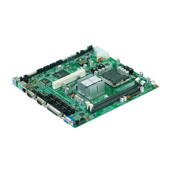
Chapter 1 Product Introduction 1.1 Overview POS-7893 is a type of motherboard dedicated for self-service terminals. This board adopts Intel®G41+ICH7 chipset and supports LGA775 Intel Core2/Quad/ Extreme processor. Onboard 2*DDRIII 1066/1333 DIMM slots with each capacity up to 2GB, dual channel supported. Board provides 4*SATA,1*Gigabit Ethernet port, 10*serial ports, 1*parallel port and 6*USB2.0 for data... - Page 8 POS-7893 High Performance POS Motherboard Storage ●4x standard Serial ATAII, transfer rate up to 300MB/s ● RTL8111D Chip ●10/100/1000 Mbps Audio ● Realtek ALC887 audio chip ●One 4 Pin CD_IN and one 2×5 Pin Header ●Three 2×5 Header USB interfaces, to coverted to 6x standard USB ports.
- Page 9 POS-7893 High Performance POS Motherboard ●1MB SPI Flash BIOS ● Support ACPI power management Environment ●Operating Temperature: 0+60℃ ●Operating Humidity: 5%-95%, non-condensing...
-
Page 10: Chapter 2 Installation Instructions
Chapter 2. Installation Instructions... -
Page 11: Interfaces Location & Dimension
Chapter 2 Installation Instructions 2.1 Interfaces Location & Dimension Following picture illustrates the dimension of board POS-7893. Please pay attention to the installation instructions. Improper installation of some components may lead to system failure. Please note: When installing the board, please wear anti-static gloves in case of any... -
Page 12: Installation Steps
POS-7893 High Performance POS Motherboard 2.2 Installation Steps Please follow the steps below to install your computer: 1. Adjust all jumpers onboard as per the user manual. 2. Install CPU 3. Install Memory 4. Install other expansion cards 5. Connect all signal lines, cables, panel control circuits and power adaptor. -
Page 13: Jumper Settings
POS-7893 High Performance POS Motherboard Select a proper memory bank that matches your motherboard. 2.5 Jumper Settings Please refer to following instructions to setup jumpers before installing your hardware devices. Remark: How to identify the PIN1 of all jumpers and interfaces: Please observe the word mark on the side of the plug socket, which will be a “1”... -
Page 14: Com2 Jumper Setting(J1,J2,J3
POS-7893 High Performance POS Motherboard Setting Clear CMOS,BIOS back to initialization Normal Status, System default Do not clear CMOS when the computer is power on, otherwise, it will cause damage to the motherboard ! 2.5.2 COM2 Jumper Setting(J1, J2, J3)... - Page 15 POS-7893 High Performance POS Motherboard COM2 RS232(Default) COM2 RS422 COM2 RS485 1-3 2-4 3-5 4-6 3-5 4-6 1-3 2-4 3-5 4-6 3-5 4-6 5-6 7-8...
-
Page 16: Hardware Switch For System Auto Boot Upon Poweron(Jat
POS-7893 High Performance POS Motherboard 2.5.3 Hardware Switch for System Auto Boot upon Power ON(JAT) Setting Open Non-auto boot Close Auto boot 2.6 Interfaces Description Please read this manual carefully before installing any external connectors, in case of any damage to the motherboard! 2.6.1 SATA(SATA1-SATA4)... - Page 17 POS-7893 High Performance POS Motherboard SATA: Signal Name 2.6.2 COM(COM1-COM10, J6, J9) Board provides 10x COM ports. Two standard DB9 serial ports COM1-COM2. COM3-COM10need to be converted to standard COM port with a covert cable.COM1-COM10 support RS232. COM2 also supports RS422/485. Users can select COM2 transmission mode.
- Page 18 POS-7893 High Performance POS Motherboard COM1-COM2: Signal Name COM3-COM10: Signal Name Signal Name SOUT...
-
Page 19: Parallel Port(Lpt
POS-7893 High Performance POS Motherboard J6,J9 are used to provide power/alert mode for COM1 COM2. Jumper Setting Function Remark COM2 +5V COM1 +5V COM2 +12V COM1 +12V COM2 VOL TAGE COM1 VOL TAGE COM2 RING Default COM1 RING Default 2.6.3 Parallel Port(LPT)... -
Page 20: Display(Vga1-Vga2
POS-7893 High Performance POS Motherboard LPT: Signal Name Signal Name STROBE DATA0 DATA1 DATA2 DATA3 DATA4 DATA5 DATA6 DATA7 ACK# BUSY SELECT AUTO FEED# ERR# INIT# SLIN# 2.6.4 Display(VGA1-VGA2) Board provides one 2×5 Pin VGA port(optional)and 1x standard DB15 VGA port. -
Page 21: Usb(Usb12, Usb34, Usb56
POS-7893 High Performance POS Motherboard Standard DB15 VGA: Signal Name Signal Name Signal Name GREEN SDA_R BLUE HS_R VS_R SCL_R 2×5 Pin VGA: Signal Name Signal Name C_RED C_GREEN 5VDDC_DATA C_BLUE HS_R VS_R 5VDDC_CLK 2.6.5 USB(USB12,USB34,USB56) Board provides 3 group 2x 5 Pin USB interfaces, to be connected to standard USB socket with... - Page 22 POS-7893 High Performance POS Motherboard USB: Signal Name Signal Name USB DATA- USB DATA+ USB DATA+ USB DATA- 2.6.6 LAN Board provides 1x 10/100/1000Mbps RJ45 LAN port with one LED on each side of the interface. The yellow one indicates data transfer status. The green one indicates network link status.
- Page 23 POS-7893 High Performance POS Motherboard Ineffective link/close No data 2.6.7 KB/MS(PS/2) PS/2 is the keyboard and mouse interface on motherboard. Users can connect the PS/2 keyboard and PS/2 mouse to the corresponding ports.(The green port is the mouse interface. The purple one is the keyboard interface ).
- Page 24 POS-7893 High Performance POS Motherboard KB_DATA KB_CLK 2.6.8 CPUFAN Board provides one 4 Pin CPUFAN interface. Please pay attention to following two points: (1) Electric current for fan≤350mA (4.2W, 12V) (2) Confirm the fan cable matches the fan socket CPUFAN:...
-
Page 25: Audio(J12, Cd_In
POS-7893 High Performance POS Motherboard 2.6.9 Audio(J12, CD_IN) Onboard audio controller, offering one 4 Pin CD_IN and one 2×5 Header. J12: Signal Name Signal Name MIC_L MIC_R SPKOUT_L SPLOUT_R LINE_L LINE_R CD_IN: Signal Name CD_L CD_GND CD_GND... -
Page 26: Gpio(Jgp
POS-7893 High Performance POS Motherboard CD_R 2.6.10 GPIO(JGP) GPIO: General Purpose Input/Output port. (Board provides expansion for I/O. When microcontroller or chipset doesn’t have enough I/O, or the system needs to adopt remote serial communications or controlling, GPIO will provide extra control and monitoring function.) -
Page 27: Front Panel Connector(Jfp
POS-7893 High Performance POS Motherboard 2.6.11 Front Panel Connector(JFP) JFP is used to connect the function buttons and indicator LED on the front panel. JFP: Signal Name Signal Name PERLED SPK+ SPK- PWRBTSW RSTBTN HDDLED- HDDLED+ Please follow the table below to connect, pay attention to the anode (+)and cathode(-),... -
Page 28: Dimm Slot(Dimm
POS-7893 High Performance POS Motherboard SPEAKER POWER RESET BUTTON BUTTON POWER LED 1) System Power LED Pins (pin1, pin3 for PWLED) Connect system power LED cable with these pins. ( pin 1 is LED anode) When system power is switched on, power LED on;when system power is switched off, power LED off. -
Page 29: Mini-Pcie Socket
POS-7893 High Performance POS Motherboard 2.6.14 MiNi-PCIE Socket Rear panel provides one standard MiNi-PCIE Socket. J4 is the MiNi-PCIE LAN_LED port. 2.6.15 Power Interface Standard ATX 20 Pin+4 Pin power interface. Signal Name Signal Name +3.3V +3.3V +3.3V -12V PS-ON... -
Page 30: Chapter 3 Bios Setup
Chapter 3. BIOS SETUP... -
Page 31: Ami Bios Flash
POS-7893 High Performance POS Motherboard Chapter 3 BIOS SETUP AMI BIOS Flash BIOS functions as a bridge connecting hardware and operating system. Hardware and software are upgrading all the time, so when your system goes wrong, for example, your system can not support the newest CPU, you need to upgrade BIOS to keep up with the latest technology. -
Page 32: Main Menu
POS-7893 High Performance POS Motherboard finishing IDE detection. 1. Power on or reboot the computer, press <DEL> to enter into BIOS SETUP Program. 2. Use the “←↑→↓” to choose the option which your want to modify, press <Enter> and then the sub-menu will show. -
Page 33: Advanced Menu
POS-7893 High Performance POS Motherboard System Time Format: Hour/Minute/ Second. System Date System Date Format: Week/ Month/Day/ Year. 3.2 Advanced Menu Note: The incorrect parameter may lead to your system failure, please set up this section carefully according to the following instructions. -
Page 34: Cpu Configuration
POS-7893 High Performance POS Motherboard 3.2.1 CPU Configuration This Read-Only option contains the detailed information of CPU, including CPU manufacturer, type, frequency, L1 cache and L2 cache, ect. C1E Support CPU C1E Function Select. Option: [Auto (default)]. Max CPUID Value Limit [Enabled]: Support this function [Disabled]: Disable this function. -
Page 35: Ide Configuration
POS-7893 High Performance POS Motherboard to support this function. Core Multi-Processing [Enabled]: Activate multi-core CPU [Disabled]: Single Core CPU PECI Enable or disable Platform Environment Control Interface. Intel(R)Speedstep(tm)tech Intel Speedstep Tech auto adjusts power voltage and frequency doubling to reduce power consumption and heat dissipation, thus enhancing CPU performance. -
Page 36: Supper Io Configuration
POS-7893 High Performance POS Motherboard ATA/IDE Configuration Mode Select: [Compatible] or [Enhanced]. Configure SATA as Configure SATA as RAID,AHCI or IDE. Primary/Secondary /Third IDE Master/Slave These six options are used to setup IDE device type. Recommend to select [Auto] to let system detect the IDE device by itself. -
Page 37: Hardware Health Configuration
POS-7893 High Performance POS Motherboard 3.2.4 Hardware Health Configuration Hardware Health Configuration Hardware health detection. BIOS will display the status of the system including system temperature, CPU temperature, CPU Fan Speed, Voltage etc.。... -
Page 38: Acpi Configuration
POS-7893 High Performance POS Motherboard 3.2.5 ACPI Configuration General ACPI Configuration... -
Page 39: Apm Configuration
POS-7893 High Performance POS Motherboard Suspend mode Select the highest ACPI sleep state the system will enter when the SUSPEND button is pressed. S1(CPU Stop Clock):CPU stops working while other equipments are still power up. S3(STR): Suspend to RAM. 3.2.6 APM Configuration... - Page 40 POS-7893 High Performance POS Motherboard RTC Power On Enable or disable RTC to generate a wake event. When enabled. System will wake on the hr::min::sec specified. Default setting is [Disabled]. Resume On LAN Enable or disable system resume on LAN.
-
Page 41: Smbios Configuration
POS-7893 High Performance POS Motherboard 3.2.7 Smbios Configuration Smbios Smi Support Enable or disable SMBIOS SMI Wrapper support for PnP Function 50-54h. -
Page 42: Usb Configuration
POS-7893 High Performance POS Motherboard 3.2.8 USB Configuration USB Devices Enabled(Read Only) This option will display the USB devices that connected to the motherboard. USB Function Enable or disable USB Function. USB2.0 Controller [Enabled]: to enable USB2.0 port. [Disabled]: to disable USB2.0 port. - Page 43 POS-7893 High Performance POS Motherboard USB2.0 Controller Mode Setup USB 2.0 transmission mode: <FullSpeed> : USB port is 1.1 spec (12Mbps) <HiSpeed>: USB port is 2.0 spec (480Mbps). Move Mouse Cursor to “USB Mass Storage Device Configuration” and press “Enter” , then following screen pops up.
-
Page 44: Onboard Lan Option Rom Configure
POS-7893 High Performance POS Motherboard 3.2.9 Onboard LAN Option ROM Configure Onboard LAN Option ROM Enable or disable Onboard LAN Option ROM. -
Page 45: Pci Pnp Menu
POS-7893 High Performance POS Motherboard 3.3 PCI PnP Menu Clear NVRAM [NO]: Keep NVRAM [YES]: Clear NVRAM Plug & Play O/S Select BIOS or PnP O/S to allocate the interrupted resource in the peripheral devices. Choose [YES], O/S will automatically allocate the resources If O/S doesn’t have the PnP function, please set this option as [NO]. -
Page 46: Boot Menu
POS-7893 High Performance POS Motherboard 3.4 Boot Menu Move Mouse Cursor to “Boot Settings Configuration” and press <Enter> key, following screen pops up:... -
Page 47: Boot Setting Configuration
POS-7893 High Performance POS Motherboard 3.4.1 Boot Setting Configuration Quick Boot This option allows BIOS to skip certain tests while booting. This will decrease the time needed to boot the system. <Enabled>: BIOS will skip 2 and 3 self-detection and accelerate POST <Disabled>: After BIOS detect load Windows O/S. -
Page 48: Boot Device Priority
POS-7893 High Performance POS Motherboard Wait For“F1”If Error If error occurs, wait for “F1”. When the error doesn’t lead to power down, then following messages will show: “Press ‘F1’ to resume” or “Press‘F1’ to Setup”, users can press F1 to make the system go on working. - Page 49 POS-7893 High Performance POS Motherboard If multi- HDD be connected, user must set up their priority. The HDD of the highest priority will display in “Boot Device Priority”.
-
Page 50: Security Menu
POS-7893 High Performance POS Motherboard 3.5 Security Menu Supervisor Password If you set up the supervisor password, it will display “Installed”. If not, it will display “Not Installed”. User Password If you set up user password, it will display “Installed”. - Page 51 POS-7893 High Performance POS Motherboard Clear User Password This option is for clearing users’ password. Press ‘Enter ‘under this option and select “yes” and press “Enter” then you can clear the password. Boot Sector Virus Protection [Enabled]: the bootable sections protection will be available. If you execute disk format or write the bootable section instruction, BIOS will send a warning.
-
Page 52: Chipset Menu
POS-7893 High Performance POS Motherboard 3.6 Chipset Menu 3.6.1 North Bridge Configuration Move Mouse Cursor to “North Bridge Configuration” and press [Enter] key, then following screen pops up. - Page 53 POS-7893 High Performance POS Motherboard Initate Graphic Adapter Select which graphics controller to use as the primary boot device. IGD Graphics Mode Select Select the video memory size of the board integrated graphic cards. It will share the video memory before installing the driver; after installing the driver, system will allocate the memory size according to DVMT.
-
Page 54: South Bridge Chipset Configuration
POS-7893 High Performance POS Motherboard DVMT Mode Select Integrated video card DVMT Mode Select. [DVMT]: dynamic shared video memory size. Drvier allocates the size of shared video memoryaccording to the size of system memory. [FIXED]: Fixed Shared Video Memory Size. Driver allocates the shared video memory according to BIOS settings. - Page 55 POS-7893 High Performance POS Motherboard Audio Controller Enable or disable the onboard audio controller. Restore on AC Power Loss Select the computer starting up status after restoring the AC power. [Power Off]: Press the power button to restart the computer when restore the AC power.
-
Page 56: Exit Menu
POS-7893 High Performance POS Motherboard 3.7 Exit Menu Save Changes and Exit Press [Enter] to select this option and press [Enter] to confirm to save all BIOS changes and Exit. Discard Changes and Exit Press [Enter] to select this option and press [Enter] to confirm to discard all changes and exit. - Page 57 POS-7893 High Performance POS Motherboard Load Failsafe Defaults Load failsafe defaults. System obtains a high stability at a lower efficiency under this setting. If system fails, this setting is very helpful.
-
Page 58: Appendix
Appendix... -
Page 59: Appendix 1: Watchdog Programming Guide
POS-7893 High Performance POS Motherboard Appendix Appendix 1: Watchdog Programming Guide watchdog reference code(ASM) -------------------------------------------------------------------------------------------------------------- Set the port to realize watchdog function through DEBUG order, so that it can carry out Watchdog Timer’s various functions. Port Instruction: 2EH: Address Register... - Page 60 POS-7893 High Performance POS Motherboard outputb (0x2f, 0xE0) //bit4=0 ,set pin as watchdog function outputb (0x2E, 0x07) outputb (0x2F, 0x08) //select logical device outputb (0x2e, 0x30) outputb (0x2f, 0x01) //active the device outputb (0x2e, 0xF5) outputb (0x2f, 0x00) //Set timing unit as second/(set as minute: outputb (0x2f, 0x08))...
-
Page 61: Appendix 2: Glossary
POS-7893 High Performance POS Motherboard Appendix 2: Glossary ACPI Advanced Configuration and Power Management。 ACPI specifications allow O/S to control most power of the computer and its add-ons BIOS Basic input/output system. It is a kind of software including all in/out control code interface in PC. - Page 62 POS-7893 High Performance POS Motherboard Dual-Inline-Memory-Modules. It is a small circuit board with memory chipset providing 64 bit memory bus width. DRAM Dynamic Random Access Memorizer. It’s a normal type of memory often with a transistor and a capacitance to store 1 bit. With the development of the technology, more and more types of DRAM with different specifications exist in computer applications.
- Page 63 POS-7893 High Performance POS Motherboard components are in normal situation and work well. PS/2 A keyboard & mouse connective interface specification developed by IBM.PS/2 is a DIN interface with only 6PIN; it also can connect other devices, like modem It is the Universal Serial Bus for short. A hardware interface adapts to low speed peripherals, and is always used to connect keyboard, mouse etc.
Need help?
Do you have a question about the POS-7893 and is the answer not in the manual?
Questions and answers