Table of Contents
Advertisement
Quick Links
Advertisement
Table of Contents

Related Manuals for Norco EMB-7536


Summary of Contents for Norco EMB-7536
- Page 1 EMB-7536 Ver:1.0...
- Page 2 EMB-7536 Ver:1.0 SZ HQ: 0755-27331166 Beijing Office: 010-82671166 Shanghai Office: 021-61212081 Chengdu Office: 028-85259319 Shenyang Office: 024-23960846 Xi’an Office: 029-88338386 Nanjing Office: 025-58015489 Wuhan Office: 027-87858983 Tianjin Office: 022-23727100 Singapore: 65-68530809 For more information, please visit:www.norco.com.cn...
- Page 3 Shenzhen NORCO Intelligent Technology Co.,Ltd. EMB-7536 Digital Signage Special Board Shenzhen NORCO Intelligent Technology Co.,Ltd. Place/Date: HONG KONG/2019...
- Page 4 Trade Name: Shenzhen NORCO Intelligent Technology Co.,Ltd. Model Name:EMB-7536 Responsible Party: Shenzhen NORCO Intelligent Technology Co.,Ltd. Equipment Classification:FCC Class B Subassembly Type of Product:EMB-7536 Digital Signage Special Board Manufacturer: Shenzhen NORCO Intelligent Technology Co.,Ltd. Date: 2019...
- Page 5 Before buying products, please learn about the product performance from the distributors to see if it is in line with your needs. NORCO is a registered trademark of Shenzhen NORCO Intelligent Technology CO., LTD.
- Page 6 Safety Instructions 1. Before using this product, please read this user’s manual carefully; 2. Any plate cards not ready to be installed shall be kept in the anti-static protective bags; 3. Before taking out the plate cards from the anti-static protective bags, first place hands on the grounding metal object for a while so as to release the static electricity from your body and hands;...
-
Page 7: Table Of Contents
Content Chapter 1 Product Introduction ......................1 1.1 Hardware Specification......................1 Chapter 2 Hardware Function ......................3 2.1 Interface Location and Dimension Diagram................3 2.2 Installation Steps........................3 2.3 Jumper Setting...........................4 2.3.1 System Programming Jumper(JD)................ 5 2.3.2 COM1、COM2、COM3 Jumper Setting(J1、J2、J3、J4、J5、J6)....5 2.4 Interface Specification...................... - Page 8 3.1.4 CAN..........................20 3.1.5 SD Card.........................20 3.1.6 WIFI Card........................20 3.1.7 4G Card......................... 20 3.1.8 Ethernet......................... 20 3.1.9 Sound Card........................21 3.1.10 Camera........................21 3.1.11 IO..........................21 3.1.12 SATA..........................21 3.2 Linux System........................... 21 3.2.1 System Version......................21 3.2.2 AI Acceleration Module....................21 Appendix ..............................22 Appendix 1:Glossary........................
- Page 9 Packing List Thanks for purchasing NORCO products. Please check the accessories as per the packing list when you open the package. If you find any components/parts defected, damaged or lost, please contact your vendor ASAP. ■ EMB-7536 motherboard 1pcs...
- Page 10 Chapter Product Introdu ction...
-
Page 11: Chapter 1 Product Introduction
EMB-7536 User’s Manual Chapter One Product Introduction 1.1 Hardware Specification Size ●Size:135mmX175mm Processor ●CPU:RK3399,hexa core (dual core A72 1.8GHz + quad core A53 1.6GHz) System Memory ●On board memory: ON BOARD memory, support LPDDR3, memory up to 4G Bytes, default Flash ●ON BOARD,support 8/16/32/64GB optional,default 8GB... - Page 12 EMB-7536 User’s Manual ●SATA:Provide 2x standard 7pin SATA port,up to 4 x standard 7pin SATA port(optional) AUDIO ●Using audio codec ES8316+NS4258T ●Provide NS4258T power amplifier output interface ●Provide 1xMic slot,1x heardphone jack ●Provide 5W2Ωdunl channel power amplifier,the interface is led out by 1x2PIN connetor ●Serial port:Provide 2x serial port,COM1-3 support RS232/485,2x3 PIN 3.81mm Phoenix...
- Page 13 EMB-7536 User’s Manual ●Provide 1x 2.0mm 2x10PIN connector GPIO pin port built in,support 16xGPIO Power Supply ●+12V single power supply,supports hardware and software switch for system auto boot upon power on Watchdog ●Support hardware reset function Operating Environment ●Operating Temperature:0℃~60℃...
-
Page 14: Chapter 2 Hardware Function
Chapter Hardware Function... -
Page 15: Installation Steps
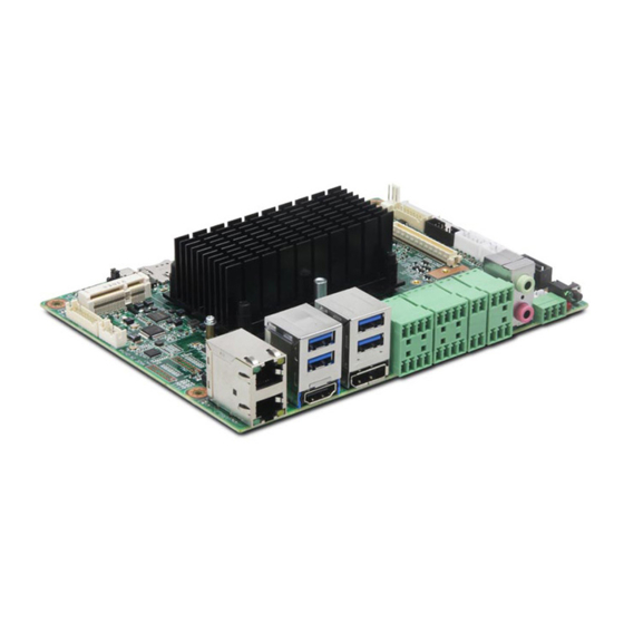
EMB-7536 User’s Manual Chapter Two Hardware Function 2.1 Interfaces Location and Dimension Following picture illustrates the front interfaces and dimension of board EMB-7536. Please pay attention to the installation process. Improper installation of some components may lead to system failure. -
Page 16: Jumper Setting
EMB-7536 User’s Manual 3.Connect all signal line, cables, panel control circuit and power adapter. Key components of this motherboard are Integrated circuit and these components could be easily damaged by electrostatic influence. So, before installing this unit, please always keep the following precautions in mind:... -
Page 17: System Programming Jumper(Jd
EMB-7536 User’s Manual 2.3.1 System Programming Jumper(JD) JD: JDOWNLOAD DOWNLOAD MODE NORMAL MODE 2.3.2 COM1、COM2、COM3 Jumper Setting(J1、J2、J3、J4、J5、J6) J1、 J2 jumpers are used to set COM1 transmission mode, COM1 support RS 232/RS 485 transmission modes , you can choose settings according to your own needs , the default transmission mode is RS232. -
Page 18: Interface Specification
EMB-7536 User’s Manual Left J1,Right J2 Left J3,Right J4 Left J5,Right J6 COM1 RS232(default) COM1 RS485 3-4 5-6 1-3 2-4 3-5 4-6 COM2 RS232( default ) COM2 RS485 3-4 5-6 1-3 2-4 3-5 4-6 2.4 Interface Specification Please read this manual carefully before connecting the external connector to... -
Page 19: Sata Port(Sata1,Sata2,Sata_Pwr1,Sata_Pwr2
EMB-7536 User’s Manual 2.4.1 SATA Port(SATA1,SATA2,SATA_PWR1,SATA_PWR2) Provide 2x standard 7pin SATA port , maximum support 4x standard 7pin SATA port (optional). 2x 5PIN SATA power supply connector. Up SATA1,Down SATA2 Left SATA_PWR1 Right SATA_PWR2 SATA1-2: Signal Name SATA_PWR1-2: Signal Name... -
Page 20: Serial Port(Com_Db,Com1_2
EMB-7536 User’s Manual +12V 2.4.2 Serial Port(COM_DB,COM1_2) Provide 3x COM port;COM1-3 support RS232/485,2x3 PIN 3.81mm Phoenix terminal interface exposed;COM_DB default Debug port,1x3 PIN 3.81mm Phoenix terminal interface exposed. COM1_2 JCOM3_4 COM_DB COM_DB: Signal Name COM_DB_RX COM_DB_TX... -
Page 21: Usb Port(Usb_Hdmi,Usb3_4,Usb56,Otg
EMB-7536 User’s Manual COM1_2: Signal Name Signal Name COM1_RXD_DATA+ COM2_RXD_DATA+ COM1_TXD_DATA- COM2_TXD_DATA- 2.4.3 USB Port(USB_HDMI,USB3_4,USB56,OTG) Provide 4x USB3.0 TYPE A port exposed, one 2xPIN 2.00mm spacing connector pin built in;1xOTG port USB56 USB_HDMI USB3_4 USB56: Signal Name Signal Name HUB_3-R... -
Page 22: Ethernet Interface(Lan1_2
EMB-7536 User’s Manual OTG: Signal Name OTG_VBUS OTG_DM_R OTG_DP_R OTG_ID_R 2.4.4 Ethernet Interface(LAN1_2) Provide 2 x 100/1000M Ethernet interface , external interface board. RJ45 network interface,Yellow indicates data transmission status, and Green indicates network connection status. LAN1_2 RJ45 LAN LED State Description:... -
Page 23: Audio Port(Audio,Amp_R,Amp_L
EMB-7536 User’s Manual 2.4.5 Audio Port(AUDIO,AMP_R,AMP_L) Provide 1x MIC IN (PH1.25/2P slot) , 1x Headphone output (PH1.25/4P slot) , and 1 x dual channel 3.2W/4Ωor 5W/2Ω power amplifier output interface(PH1.25/4P slot). AUDIO Up AMP_R,Down AMP_L AMP_R: Signal Name AMP_R- AMP_R+ AMP_L:... - Page 24 EMB-7536 User’s Manual USB_HDMI JVGA JVGA: Signal Name Signal Name VGA_R VGA_G SDA_R VGA_B HSYNC VSYNC VGA_PIN10 SCL_R HDMI: Signal Name Signal Name TX2P TX2N TX1P TX1N TX0P TX0N TXCP TXCN PORT_CEC DDC_SCL DDC_SDA...
-
Page 25: Programmable I / O Port(Jgpio
EMB-7536 User’s Manual 5V_OUT PORT_HPD DP: Signal Name Signal Name DP0P DP0N DP1P DP1N DP2P DP2N DP3P DP3N DP_AUXP DP_AUXN DP_HPD +3.3V 2.4.7 Programmable I / O Port(JGPIO) JGPIO... -
Page 26: Power Interface(Pwr_In
EMB-7536 User’s Manual JGPIO: Signal Name Signal Name I2C4_SCL I2C4_SDA GPIO2_B3 GPIO4_A7 GPIO2_B0 GPIO4_A6 GPIO2_A7 GPIO0_B4_3 GPIO2_A6 GPIO4_A4 GPIO2_A5 GPIO4_C5 GPIO2_A4 GPIO4_C0 GPIO2_A3 GPIO4_B2 GPIO2_A1 GPIO4_B4 2.4.8 Power Interface( PWR_IN ) PWR_IN PWR: Signal Name +12V... -
Page 27: Port
EMB-7536 User’s Manual +12V GND_IN GND_IN 2.4.9 Port (AI,DI,DO1_2) Provide 4x DI,support dry contact and wet contact input ,2x4 PIN 3.81mm Phoenix terminal interface exposed. 4x AI input, 2x4 PIN 3.81mm Phoenix terminal interface exposed 上 AI,下 DI DO1_2 AI:... -
Page 28: Can Port
EMB-7536 User’s Manual DIN2 DIN3 DIN4 DO1_2: Signal Name Signal Name 2.4.10 CAN Port CAN: Signal Name VCC5 CAN_H CAN_L... -
Page 29: Typec Port(Reserve
EMB-7536 User’s Manual 2.4.11 TYPEC Port(Reserve) TYPE-C Note : The TYPE-C interface is used by HUAWEI Atlas 200 interface debug. Please consult the Engineer for details! -
Page 30: J8 Port(Reserve
EMB-7536 User’s Manual 2.4.12 J8 Port(Reserve) Note: J8 interface is used to connect HUAWEI Atlas 200 interface. Please consult the Engineer for details ! -
Page 31: Reset Key(Rst
EMB-7536 User’s Manual 2.4.13 Reset Key(RST)... -
Page 32: Led Indicator
EMB-7536 User’s Manual 2.4.14 LED Indicator 2.4.15 Fan Interface(SYS_FAN) Board with 1x 3Pin SYS system fan interface, pay attention to the following two points when using the fan: (1)Fan current ≤ 500mA(6W,12V) (2)Please confirm that the fan wiring is consistent with the wiring of this socket. -
Page 33: Front Panel Interface(Jfp
EMB-7536 User’s Manual SYS_FAN SYS_FAN: Signal Name +12V 2.4.16 Front Panel Interface(JFP) JFP is used to connect to the function buttons and indicators set on the front panel of the chassis. -
Page 34: Expansion Interface(Mini_Pcie,Jpcie
EMB-7536 User’s Manual JFP: Signal Name Signal Name PWRLED JFP_RST JFP_PWRSW 2.4.17 Expansion Interface(MINI_PCIE,JPCIE) Provide 1x MINI PCIe slot,support Mini-PCIE 3G/4G;One 2x10PIN PCIE port... - Page 35 EMB-7536 User’s Manual MINI_PCIE JPCIE JPCIE: Signal Name Signal Name VCC3 VCC3 VCC3 VCC5 VCC5 VCC5 VCC12_S VCC12_S PER_PCIE_RXP7 PER_PCIE_TXP7 PER_PCIE_RXN7 PER_PCIE_TXN7 REFCLKN5_1 GPIO4_AS REFCLKP5_1 ASM1061_RST...
- Page 36 Chapter Three Software Function...
-
Page 37: Chapter Three Software Function
EMB-7536 User’s Manual Chapter Three Software Function 3.1 Android System 3.1.1 Display Support VAG、HDMI and DP port independent output Support dual screen separate display. 3.1.2 USB 4x USB3.0 ports,2x USB2.0 ports,support USB flash disk、USB keyboard, mouse and other devices USB flash disk auto mount directory: /mnt/media_rw/, the specific path are related to the USB flash disk. -
Page 38: Sound Card
EMB-7536 User’s Manual 3.1.9 Sound Card Support for local sound card and HDMI dual channel sound card. Local sound card supports a pair of independent headphone, and MIC. 3.1.10 Camera Support USB camera,support dual cameras working at the same time,provide demo. -
Page 39: Appendix
Appen... -
Page 40: Appendix 1:Glossary
EMB-7536 User’s Manual Appendix Appendix 1:Glossary BUS is a channel for different devices to exchange data in computer system. It is hardware circuit. BUS here refers to partial lines inside CPU and the main components of system memory. Chipset Chipset is an Integrated set of chips for executing one or more related functions。Here it refers to a system level chipset structured by Southbridge &... - Page 41 EMB-7536 User’s Manual DRAM Dynamic Random Access Memory. It is a general type of memory for regular computer which usually store 1 bit with a transistor and a capacitance. With the development of the technology, more and more types of DRAM with different specifications exist in computer applications.
Need help?
Do you have a question about the EMB-7536 and is the answer not in the manual?
Questions and answers