Table of Contents
Advertisement
Quick Links
Advertisement
Table of Contents

Related Manuals for Norco SOMB-073


Summary of Contents for Norco SOMB-073
- Page 1 SOMB-073 QSEVEN Carrier Board User Manual V1.0...
-
Page 2: Table Of Contents
Content Chapter 1 Product Introduction......................1 1.1 Product Specification ......................1 Chapter 2 Interface Instruction ......................3 2.1 Interface Location and Dimension Diagram ..............3 2.2 Jumper Setting........................3 2.2.1 Start Upon Power-on Hardware Switch(JAT)............4 2.2.2 COM2 Jumper Setting(J5, J6, J7) ..............4 2.2.3 LVDS Voltage Jumper Setting(JLVDS) .............5 2.3 Interface Specification ......................6 2.3.1 SATA Interfaces(SATA1, SATA2, JSATA)... -
Page 3: Chapter 1 Product Introduction
Chapter 1. Product Introduction... -
Page 4: Product Specification
SOMB-073 QSEVEN Carrier Board Chapter 1 Product Introduction 1.1 Product Specification Standard Structure ●QSEVEN Carrier Board ●Conforms to MINI-ITX specification with a dimension of 170mm×170mm Storage ●2* standard SATA interfaces ●1*SDIO port compatible with MMC Display Interface ●1*standard DB15 VGA port with resolution up to 1280×1024@85Hz ●1*2×10Pin supporting 24/18bit LVDS interface with resolution up to 1280×768@60Hz... - Page 5 SOMB-073 QSEVEN Carrier Board Expansions ●1*PCIE_×1 ●1*MINI-PCIE Power Supply ●+12V Single Power Supply Environment ●Operating Temperature: -40℃-80℃(Industrial grade) 0℃-60℃(commercial grade) ●Storage Temperature: -40℃-85℃ ●Operating Humidity: 0-95% relative humidity, no-condensing...
- Page 6 Chapter 2. Interface Instruction...
-
Page 7: Chapter 2 Interface Instruction
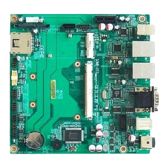
Chapter 2 Interface Instruction 2.1 Interface Location and Dimension Diagram The following picture is the interface index for SOMB-073. When you install this device, please consult it and read the following instruction. During the installation, please care for some devices, as the improper installation of some components will lead to system failure. -
Page 8: Start Upon Power-On Hardware Switch(Jat)
SOMB-073 QSEVEN Carrier Board 2.2.1 Start Upon Power-on Hardware Switch(JAT) Power Mode Close Self-start upon power on Open Non self-start upon power on 2.2.2 COM2 Jumper Setting(J5, J6, J7) J5,J6,J7 are used to config the transmission mode of COM2. COM2 supports... -
Page 9: Lvds Voltage Jumper Setting(Jlvds
SOMB-073 QSEVEN Carrier Board J5,J6 COM2 RS232 COM2 RS422 COM2 RS485 3-5 4-6 1-3 2-4 1-3 2-4 3-5 4-6 1-3 2-4 1-3 2-4 5-6 7-8 2.2.3 LVDS Voltage Jumper Setting(JLVDS) Before usint the chosen LVDS, please make clear of its rated voltage for operating. Thenyou... -
Page 10: Interface Specification
SOMB-073 QSEVEN Carrier Board Signal Name 3.3V 2.3 Interface Specification Before connecting external interface, please read this manual carefully, it will protect motherboard from damage 2.3.1 SATA Interface(SATA1, SATA2, JSATA) 2*standard SATA interfaces.SATA1 is the 7+15Pin interface. JSATA is the power supply... - Page 11 SOMB-073 QSEVEN Carrier Board SATA1: Signal Name Signal Name SATA_TX_P0 SATA_TX_N0 SATA_RX_N0 SATA_RX_P0 +12V VCC3 +12V VCC3 +12V VCC3 SATA2: Signal Name...
-
Page 12: Serial Ports(Com1,Com2
SOMB-073 QSEVEN Carrier Board JSATA: Signal Name +12V VCC3 2.3.2 Serial Ports(COM1, COM2) Board provides 2* serial ports. COM1 adopts the standard DB9 interface. COM2 adopts 2×5Pin interface. These serial ports need to be converted to DB9 port via a convert cable , so as to connect external devices. - Page 13 SOMB-073 QSEVEN Carrier Board COM1: Signal Name COM2: Signal Name Signal Name...
-
Page 14: Display Interface(Vga, Lvds
SOMB-073 QSEVEN Carrier Board 2.3.3 Display Interface (VGA,LVDS) Onboard provides one standard VGA interface and one 20Pin LVDS interface(supporting 18/24bi with resolution up to 1280×768@60Hz) 。 VGA: Signal Name Signal Name Signal Name GREEN BLUE HSYNC VSYNC 5VDDCK LVDS: Signal Name... -
Page 15: Lvds Backlight Control(Jlvds
SOMB-073 QSEVEN Carrier Board LVDS_D0+ DDC_CLK LVDS_D1- LVDS _CLK- LVDS_D1+ LVDS _CLK+ LVDS_D2- LVDS_D3- / NC LVDS_D2+ LVDS_D3+ /NC 2.3.4 LVDS Backlight Control(JLVDS) JLVDS is used to adjust the brightness of LVDS backlight panel. JLVDS: Signal Name +12V L-BKLT_EN L-BKLTCLT... -
Page 16: Usb Ports(Usb, Usb45
SOMB-073 QSEVEN Carrier Board 2.3.5 USB Ports(USB, USB45) Board provides 6 USB ports, including 2 group double-layer standard USB ports and one 2×5Pin USB port. USB: Signal Name USB DATA- USB DATA+ USB45: Signal Name Signal Name USBD4+ USBD4- USBD5+... -
Page 17: Network Interface(Lan
SOMB-073 QSEVEN Carrier Board 2.3.6 Network Interface(LAN) Board provides 2*RJ 45. Both sides of RJ-45 Ethernet port will have one LED indicator. The yellow on indicates the status of data transmission, while the green one indicates network connection status. RJ45 PORT LED Status... - Page 18 SOMB-073 QSEVEN Carrier Board MS: Signal Name MS_DAT A MS_CLK KB: Signal Name KB_DATA KB_CLK...
-
Page 19: Audio Interface (Audio)
SOMB-073 QSEVEN Carrier Board 2.3.8 Audio Interface (AUDIO) Board provides one group triple-layer AUDIO interface, supporting LINE-OUT(GREEN), LINE-IN(BLUE)and MIC-IN(PINK). 2.3.9 GPIO Connector(JGP) It provides I/O expansions. When the micro-controller or the chipset doesn’t have enough I/O, or system needs to adopt remote serial communication and control, GPIO can help... - Page 20 SOMB-073 QSEVEN Carrier Board JGP: Signal Name Signal Name GP30 GP31 GP34 GP32 GP35 GP33 GP36 GP37...
-
Page 21: Power Interface(Dc_Jack)
SOMB-073 QSEVEN Carrier Board 2.3.10 Power Interface(DC_JACK) 2.3.11 Front Panel Connector(JFP) JFP is used to connect the function buttons and LED indicators on the front panel. - Page 22 SOMB-073 QSEVEN Carrier Board JFP: Signal Name Signal Name PWR_LED+ HDD_LED+ HDD_LED- SPK- RSTBTN- POWERSW+...
-
Page 23: Sd Card Socket
SOMB-073 QSEVEN Carrier Board 2.3.12 SD Card Socket SD Card Socket 2.3.13 PCIE_X1 Port Board provides one PCIE_X1 port , which is able to connect expansion devices. 2.3.14 MiniPCIE Port(MINI_PCIE) Onboard provides one standard MINI_PCIE port,Users can use this port to expand the Mini...
Need help?
Do you have a question about the SOMB-073 and is the answer not in the manual?
Questions and answers