Sign In
Upload
Manuals
Brands
Cambium Networks Manuals
Wireless Access Point
PMP 450
Cambium Networks PMP 450 Manuals
Manuals and User Guides for Cambium Networks PMP 450. We have
3
Cambium Networks PMP 450 manuals available for free PDF download: Planning Manual, Configuration And User's Manual, User Manual
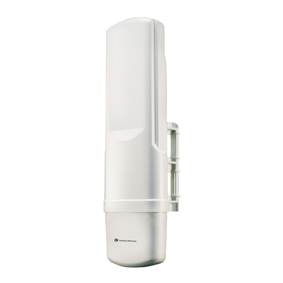
Cambium Networks PMP 450 Planning Manual (223 pages)
wireless access network platform
Brand:
Cambium Networks
| Category:
Wireless Access Point
| Size: 2 MB
Table of Contents
PMP 450 Module Essential Information
2
Safety and Regulatory Information
4
Table of Contents
6
About this Planning Guide
14
General Information
15
Version Information
15
Contacting Cambium Networks
15
Problems and Warranty
17
Security Advice
19
Warnings, Cautions, and Notes
20
Overview of PMP 450
21
Purpose
21
Key Features
21
Typical Deployment
22
Figure 1 Line of Sight Diagram
22
System Components
23
Table 1 PMP 450 Frequency Variants
24
Access Point (AP)
25
Figure 2 AP, Radio Unit
25
Figure 4 AP Interfaces - 2.4 Ghz, 3.5 Ghz, 3.6Ghz, 5 Ghz
26
Table 2 AP Interface Descriptions and Cabling - 2.4 Ghz, 3.5 Ghz, 5 Ghz
26
Figure 5 AP Interfaces - 5 Ghz Original Layout
27
Table 3 AP Interface Descriptions and Cabling - 5 Ghz Original Layout
27
Figure 6 AP Ground and Equilibrium Membrane Vent
28
Figure 7 AP Diagnostic Leds, Viewed from Front of the Unit
28
Table 4 AP Interface Descriptions and Cabling - Ground Lug
28
AP Power Supply
29
Network Connection
29
Table 5 AP LED Descriptions
29
Figure 8 Radio Tab of the AP
30
Radio Tab of the AP
30
Table 6 AP Radio Attributes
31
Further Reading on the AP
35
Subscriber Module (SM)
36
Mounting Brackets
36
Network Connection
36
SM Power Supply
36
Figure 9 PMP 450 Series SM
36
Further Reading on the SM
37
Figure 10 SM Interfaces
37
Figure 11 Connectorized SM
38
Table 7 SM Interfaces
38
Figure 12 SM Diagnostic Leds, Viewed from Front of the Unit
39
Table 8 SM Diagnostic LED Descriptions
40
Radio Tab of the SM
41
Figure 13 Radio Tab of the SM
41
Figure 14 Custom Frequency Tab of the SM
42
Table 9 SM Radio Attributes
43
Cabling and Lightning Protection
46
PMP and Lightning Protection
46
Outdoor Connections
46
Wireless Operation
47
Time Division Duplexing
47
OFDM and Channel Bandwidth
47
Figure 15 TDD Frame Division
47
Link Operation - Dynamic Rate Adapt
48
Table 10 Link Budget Details - Dynamic Rate Adapt, 5.4 Ghz
49
Table 11 Link Budget Details - Dynamic Rate Adapt, 5.8 Ghz
50
Table 12 Link Budget Details - Dynamic Rate Adapt, 2.4Ghz
51
Table 13 Link Budget Details - Dynamic Rate Adapt, 3.5Ghz
52
Table 14 Link Budget Details - Dynamic Rate Adapt, 3.6Ghz
53
Table 15 Link Budget Details - Dynamic Rate Adapt, 5.4Ghz PMP 450 AP and PMP 430 SM
54
Table 16 Link Budget Details - Dynamic Rate Adapt, 5.8Ghz PMP 450 AP and PMP 430 SM
55
Adaptive Modulation
56
Mimo
56
Cyclic Prefix
56
Encryption
56
Further Reading on Wireless Operation
56
System Management
57
Management Agent
57
Web Server
57
Figure 16 AP Web-Based Management Screenshot
58
Remote Authentication Dial in User Service (RADIUS)
60
Snmp
60
Network Time Protocol (NTP)
61
Wireless Manager (WM)
61
Capacity Upgrades
62
Software Upgrade
62
Further Reading on System Management
63
Chapter 1: Planning Considerations
64
Regulatory Planning
65
Obeying Regulatory Limits
65
Conforming to the Limits
65
Network Migration Planning
66
Example PMP 450 Deployment Scenario
66
Table 17 Deployment Scenario Terminology Descriptions
66
Sector Capacity
68
Table 18 Examples of Aggregate Sector Throughput - FSK (PMP 1X0 Series)
68
Table 19 Examples of Aggregate Sector Throughput - OFDM (PMP 430 Series)
68
Table 20 Examples of Aggregate Sector Throughput - OFDM MIMO (PMP 450 Series)
69
Table 21 Examples of Aggregate Sector Throughput - PMP 450 AP to PMP 430 SM
70
Table 22 Deployment Scenario 1
70
Table 23 Scenario 1 Spectrum Usage
71
Table 24 Deployment Scenario 2
73
Table 25 Deployment Scenario 2 Spectrum Usage
74
Site Planning
75
AP or SM Site Selection
75
Power Supply Site Selection
75
Maximum Cable Lengths
75
Table 26 Sync Cable Length Specification
75
Wind Loading
76
Table 27 Lateral Force - Metric
76
Table 28 Lateral Force - US
77
Link Planning
79
Range and Obstacles
79
Table 29 Link Budget Details - 5.8 Ghz PMP 450 Link, 20 Mhz Channel Bandwidth
80
Table 30 Link Budget Details - 5.8 Ghz PMP 450 Link, 10 Mhz Channel Bandwidth
81
Table 31 Link Budget Details - 5.8 Ghz PMP 450 Link, 5 Mhz Channel Bandwidth
83
Table 32 Link Budget Details - 5.4 Ghz PMP 450 Link, 20 Mhz Channel Bandwidth
84
Table 33 Link Budget Details - 5.4 Ghz PMP 450 Link, 10 Mhz Channel Bandwidth
85
Table 34 Link Budget Details - 5.4 Ghz PMP 450 Link, 5 Mhz Channel Bandwidth
86
Table 35 Link Budget Details - 2.4 Ghz PMP 450 Link, 20 Mhz Channel Bandwidth
87
Table 36 Link Budget Details - 2.4 Ghz PMP 450 Link, 10 Mhz Channel Bandwidth
88
Table 37 Link Budget Details - 2.4 Ghz PMP 450 Link, 5 Mhz Channel Bandwidth
89
Table 38 Link Budget Details - 3.5 Ghz PMP 450 Link, 20 Mhz Channel Bandwidth
90
Table 39 Link Budget Details - 3.5 Ghz PMP 450 Link, 10 Mhz Channel Bandwidth
91
Table 40 Link Budget Details - 3.5 Ghz PMP 450 Link, 5 Mhz Channel Bandwidth
92
Table 41 Link Budget Details - 3.6 Ghz PMP 450 Link, 20 Mhz Channel Bandwidth
93
Table 42 Link Budget Details - 3.6 Ghz PMP 450 Link, 10 Mhz Channel Bandwidth
94
Table 43 Link Budget Details - 3.6 Ghz PMP 450 Link, 5 Mhz Channel Bandwidth
95
Table 44 Link Budget Details - 5.8Ghz PMP 450 AP and PMP 430 SM Link, 20Mhz Channel Bandwidth
96
Table 45 Link Budget Details - 5.8Ghz PMP 450 AP and PMP 430 SM Link, 10Mhz Channel Bandwidth
97
Table 46 Link Budget Details - 5.8Ghz PMP 450 AP and PMP 430 SM Link, 5Mhz Channel Bandwidth
98
Table 47 Link Budget Details - 5.4Ghz PMP 450 AP and PMP 430 SM Link, 20Mhz Channel Bandwidth
99
Table 48 Link Budget Details - 5.4Ghz PMP 450 AP and PMP 430 SM Link, 10Mhz Channel Bandwidth
100
Table 49 Link Budget Details - 5.4Ghz PMP 450 AP and PMP 430 SM Link, 5Mhz Channel Bandwidth
101
Path Loss Considerations
102
Calculating Maximum Power Level for Connectorized AP Units
102
Understanding Attenuation
102
Calculating Link Loss
103
Calculating Rx Signal Level
103
Figure 17 Determinants in Rx Signal Level
103
Calculating Fade Margin
104
Analyzing the RF Environment
104
Mapping RF Neighbor Frequencies
104
Analyzing the Spectrum
105
Anticipating Reflection of Radio Waves
106
Noting Possible Obstructions in the Fresnel Zone
106
Multiple OFDM Access Point Clusters
107
Figure 18 Example Layout of 16 Access Point Sectors (ABCD), 90 Degree Sectors
107
Table 50 Example 5.8-Ghz OFDM Channel Assignment by Sector
107
Figure 19 Example Layout of 16 Access Point Sectors (ABC), 60 Degree Sectors
108
Table 51 Example 5.8-Ghz OFDM Channel Assignment by Sector
108
Planning for Co-Location and Using the OFDM Frame Calculator Tool
109
Figure 20 OFDM Frame Calculator Tab
110
Table 52 OFDM Frame Calculator Tab Attributes
110
Table 53 OFDM Calculated Frame Results Attributes
111
Selecting Sites for Network Elements
112
Surveying Sites
113
Clearing the Radio Horizon
113
Calculating the Aim Angles
114
Figure 21 Variables for Calculating Angle of Elevation (and Depression)
114
Diagramming Network Layouts
115
Avoiding Self Interference
115
Avoiding Other Interference
116
Grounding and Lightning Protection
117
The Need for Power Surge Protection
117
Standards
117
Lightning Protection Zones
118
Figure 22 Rolling Sphere Method to Determine the Lightning Protection Zones
118
General Protection Requirements
119
Figure 23 Grounding Cable Minimum Bend Radius and Angle
119
Protection Requirements for a Mast or Tower Installation
120
Figure 24 Grounding and Lightning Protection on Mast or Tower
120
Protection Requirements for a Wall Installation
121
Figure 25 Grounding and Lightning Protection on Wall
121
Protection Requirements on a High Rise Building
122
Figure 26 Grounding and Lightning Protection on Building
124
Figure 27 Grounding and Lightning Protection Inside High Building
124
Configuration Options for TDD Synchronization
125
GPS Synchronization
126
Figure 28 One Unsynchronized AP in Cluster Resulting in Self-Interference
127
Figure 29 GPS Timing Throughout the Network
127
Mounting the GPS Receiver (CMM or UGPS) Module on the Equipment Building
128
Mounting the GPS Receiver (CMM or UGPS) Module on a Metal Tower or Mast
128
Data Network Planning
129
Understanding Addresses
129
Dynamic or Static Addressing
129
DNS Client
130
Network Address Translation (NAT)
130
Figure 30 Cambium Network Management Domain
130
Developing an IP Addressing Scheme
131
Address Resolution Protocol
131
Allocating Subnets
132
Figure 31 Example of IP Address in Class B Subnet
132
Translation Bridging
133
Engineering Vlans
133
Table 54 Special Case VLAN Ids
134
Table 55 VLAN Filters in Point-To-Multipoint Modules
135
Table 56 Q-In-Q Ethernet Frame
136
Security Planning
137
Isolating Aps from the Internet
137
Managing Module Access by Passwords
137
Table 57 Identity-Based User Account Permissions - AP
138
Table 58 Identity-Based User Account Permissions - SM
140
Filtering Protocols and Ports
141
Figure 32 Categorical Protocol Filtering
143
Port Lockdown
144
Isolating Sms
144
Table 59 Ports Filtered Per Protocol Selections
144
Table 60 Device Default Port Numbers
144
Filtering Management through Ethernet
145
Allowing Management from Only Specified IP Addresses
145
Configuring Management IP by DHCP
145
Planning for Airlink Security
146
Planning for RF Telnet Access Control
146
Forwarding Downlink Pppoe PADI Packets
146
Planning for RADIUS Integration
146
Planning for SNMP Security
147
Ordering Components
148
PMP 450 Component Part Numbers
148
Table 61 PMP 450 Components
148
Chapter 2: Legal Information
156
Cambium Networks End User License Agreement
157
Acceptance of this Agreement
157
Definitions
157
Grant of License
157
Conditions of Use
157
Title and Restrictions
158
Confidentiality
159
Right to Use Cambium's Name
159
Transfer
159
Updates
159
Maintenance
160
Disclaimer
160
Limitation of Liability
160
U.S. Government
161
Term of License
161
Governing Law
161
Assignment
161
Survival of Provisions
161
Entire Agreement
162
Third Party Software
162
Hardware Warranty
165
Limit of Liability
166
Chapter 3: Reference Information
167
Equipment Specifications
168
AP Specifications
168
Table 62 Connectorized AP Physical Specifications
168
SM Specifications
173
Table 63 SM Physical Specifications
173
Wireless Specifications
176
General Wireless Specifications
176
Table 64 PMP 450 Wireless Specifications
176
Data Network Specifications
177
Ethernet Interface
177
Table 65 PMP 450 Ethernet Bridging Specifications
177
Compliance with Safety Standards
178
Electrical Safety Compliance
178
Electromagnetic Compatibility (EMC) Compliance
178
Table 66 PMP 450 Safety Compliance Specifications
178
Table 67 EMC Emissions Compliance
178
Human Exposure to Radio Frequency Energy
179
Table 68 Power Compliance Margins
181
Compliance with Radio Regulations
183
Type Approvals
183
Table 69 Radio Certifications
183
DFS for 5.4 Ghz Radios
184
Figure 33 AP DFS Status
184
Table 70 OFDM DFS Operation Based on Country Code Setting
185
Country Codes and Available Spectrum
186
Table 71 Center Channel Details Based on Country Code, 2.4 Ghz
187
Table 72 AP Default Combined Transmits Power Per Country Code and Lower/Upper Band Edge Path Max TX Detail, 2.4 Ghz
188
Table 73 Center Channel Details Based on Country Code, 3.5 Ghz
189
Table 74 AP Default Combined Transmit Power Per Country Code - 3.5 Ghz Band
191
Table 75 Center Channel Details Based on Country Code, 3.6 Ghz
192
Table 76 AP Default Combined Transmit Power Per Country Code - 3.6 Ghz Band
194
Table 77 Center Channel Details Based on Country Code, 5.4 Ghz
195
Table 78 Center Channel Details Based on Country Code, 5.8 Ghz
196
Table 79 Default Combined Transmit Power Per Country Code - 5.4 Ghz Band
197
Table 80 Default Combined Transmit Power Per Country Code - 5.8 Ghz Band
200
FCC Compliance Testing
202
FCC and ICC Ids and Certification Numbers
202
Table 81 US FCC Ids and Industry Canada Certification Numbers and Covered Configurations
202
Notifications
208
PMP 450 Regulatory Compliance
208
Table 82 Industry Canada Approved Antenna List
209
Appendix A: Glossary
213
Table 83 Glossary
213
Advertisement
Cambium Networks PMP 450 User Manual (172 pages)
Cambium PMP Synchronization Solutions
Brand:
Cambium Networks
| Category:
Wireless Access Point
| Size: 5 MB
Table of Contents
User Guide
1
Safety and Regulatory Information
3
Table of Contents
5
General Information
13
Version Information
13
Contacting Cambium Networks
13
Caring for the Environment
14
Chapter 1: Introduction to Synchronization
15
Interference and Reliability
16
Exclusivity and Free Use of Spectrum
16
Sources of Interference
17
Neutralizing Interference
18
GPS Synchronization
18
Figure 1 GPS Synchronization
18
Configuration Options for TDD Synchronization
19
Alternative to GPS Synchronization
20
Figure 2 One Unsynchronized AP in Cluster Resulting in Self-Interference
20
Cambium's Synchronization Solutions
21
Universal GPS (UGPS)
21
Figure 3: Universal GPS (UGPS)
21
Cmm5
22
CMM4 (Rack Mount)
22
CMM4 (Cabinet with Switch)
23
CMM4 (Cabinet Without Switch)
23
Cmmmicro (CMM3) - Product Is End of Life and no Longer Available for New Shipments
24
Chapter 2: Cambium Cluster Management Module (CMM5)
25
Product Overview
26
Cluster Management: Scenario 2
27
CMM5 Controller Module
28
Figure 11: Controller Module
28
CMM5 Injector Module
29
CMM5 Injector Compatibility Matrix
29
Figure 12: Injector Module
29
CMM5 Specifications
30
240 Watt Power Supply
31
Power Supply Selection (When to Use each One)
32
Power Line Filter
32
Figure 13: DC Line Filter
32
Ferrite Beads
33
What's in each Box
33
Providing Sync to CMM5 Via Ugps Module
34
Figure 14: UGPS Module
34
CMM5 Planning
35
Injector Cabling
35
Controller Cabling
35
CMM5 Injector Initial Startup
36
Injector Initial Startup
36
CMM5 Controller Initial Startup
37
Controller Initial Startup
37
CMM5 Controller Configuration
38
Log in
38
Reset Password
38
View System Status
39
View Network -Interface Status
40
View Synchronization Status
41
View Chassis Status
42
Identify a Chassis
43
View Port Status
44
View/Configure Static Routes
45
Set Local Time/Ntp Protocol
46
Update Injector Firmware
47
Update Controller Firmware
48
Installing the CMM5
49
Avoiding Hazards
49
Grounding Equipment
49
Conforming to Regulations
50
Protecting Cables and Connections
50
Testing the Components
50
Unpacking Components
50
Installing a Ugps Antenna
51
Installing a Single Controller
51
Figure 15 Installing a Single Controller
52
Installing a Single Injector
53
Figure 16: Installing a Single Injector
53
Installing Two Injectors Side by Side
54
Figure 17: Two Injectors with Joining Bar
55
Figure 18: Rear Attaching Screw
55
Installing a Controller/Injector Side by Side
56
Installing a 600 Watt Power Supply
57
Figure 19: Injector/Controller Combination
57
Figure 20: 600 Watt Power Supply Installation
58
Figure 21: 600 Watt Power Supply Installation (Rear View)
59
Installing a Split DC Power Line
60
Figure 22: Installing a Split DC Power Line
60
Cabling the CMM5
61
Figure 23: Wiring the Power Connector
62
Class a Emissions Requirements
63
Chapter 3: Cambium Cluster Management Module (CMM4)
64
CMM4 and Controller Board
65
Table 1 CMM4 Model Numbers and Ethernet Switch Configurations
65
Figure 24 CMM4 Internal View, Including Cable Glands
66
Figure 25 Rackmount CMM4
67
Figure 26 GPS Antenna
68
Power
69
Table 2 Power Supply Part Numbers
69
Ethernet Switch
70
Specifications
71
Table 3 CMM4 Specifications
71
Table 4 Rackmount CMM4 Specifications
72
Providing Sync to CMM Via UGPS Module
73
CMM Planning
74
Typical Ethernet Cabling
74
Standard Ethernet Cabling Configuration
74
Figure 27 CMM4 Standard Configuration
75
Figure 28 Rackmount CMM4 Standard Configuration
75
Figure 29 CMM4 Cabled to Use Gigabit Ethernet Feed
77
Figure 30 CMM4 Cabled to Support PTP 500/600
78
Power Planning
79
Syncing Two Co-Located Cmms Together
81
Cables
83
Table 5 Recommended Ethernet Cables
83
Table 6 RJ-45 Pinouts for Straight-Through Ethernet Cable - 30 VDC
83
Figure 31 Location of Pin 1
84
Table 7 RJ-45 Pinouts for Straight-Through Ethernet Cable - 56 VDC
84
Table 8 Recommended Antenna Cable
84
Table 9 Wire Size for CMM4 DC Cable
85
Figure 32 CMM Sync Cable Pinout
86
Etherwan Switch Information
87
Table 10 Etherwan Switch Details
87
Configuring a CMM4
89
Configuring IP Communications Parameters
89
Figure 34 IP Tab of CMM4
89
Table 11 IP Tab Attributes
89
Overriding Forgotten IP Addresses, Usernames, or Passwords
90
Log in
93
Figure 35 Login Page of CMM4
93
User Update
94
Figure 36 Changer Users Password Tab of CMM4
94
Table 12 Change User Password Tab Attributes
94
Add User
95
Figure 37 Add User Tab of CMM4
95
Table 13 Add User Attributes
95
Delete User
96
Configuring the CMM4 Ports
96
Figure 38 Delete User Tab of CMM4
96
Figure 39 Port Configuration Tab of CMM4
96
Table 14 Delete User Attributes
96
Configuring General CMM4 Parameters
97
Figure 40 CMM4 Configuration Tab
97
Table 15 Port Configuration Attributes
97
Table 16 CMM Tab Attributes
98
Configuring the SNMP Parameters
99
Table 17 Link Speed Selections for CMM4
99
Figure 41 SNMP Tab of CMM4
100
Table 18 SNMP Tab Attributes
101
Configuring VLAN
102
Figure 42 VLAN Tab of CMM4
102
Table 19 VLAN Tab Attributes
102
Configuring the Unit Settings
103
Figure 43 Unit Settings Tab of CMM4
103
Table 20 Unit Settings Tab Attributes
103
Viewing the ARP Table (Statistics)
104
Figure 44 ARP Table
104
Table 21 ARP Table Tab Attributes
104
Viewing General Status
105
Figure 45 General Status Tab of CMM4
105
Table 22 General Status Tab Attributes
106
Viewing Sync Status
108
Figure 46 Sync Status Tab of CMM4
108
Table 23 Sync Status Tab Attributes
108
Viewing the System Log
109
Figure 47 System Log Tab of the CMM
109
Viewing the Network Interface
110
Viewing Layer 2 Neighbors
110
Figure 48 Network Interface Tab of the CMM
110
Figure 49 Layer 2 Neighbors Log
110
Table 24 Network Interface Tab Attributes
110
Installing a CMM4
111
Avoiding Hazards
111
Grounding Equipment
111
Conforming to Regulations
112
Protecting Cables and Connections
112
Testing the Components
112
Unpacking Components
112
Cables
112
Installing a GPS Antenna
112
Figure 50 Detail of GPS Antenna Mounting
113
Figure 51 Weatherproofing an N-Type Antenna Connector
114
Figure 52 AP/BHM to UGPS Cable
115
Table 25 AP/BHM to UGPS Cable Pinout
115
Installing the Power Supply for the CMM4 (30 VDC or 54 VDC)
116
Figure 53 Power Supply DC Connection
116
Figure 54 Power Supply AC Connection
117
Figure 55 CMM4 Line Filter Installation (EU Only)
118
Figure 56 Rackmount CMM Line Filter Installation (EU Only)
119
Temperature Range
121
Installing a CMM4 (Models 1090CKHH and 1091HH)
121
Figure 57 Resistor When Using both 56 VDC and 30 VDC Power
121
Figure 58 CMM4 V-Bracket to Pole Mounting
122
Installing a Rackmount CMM4 (Model 1092HH)
123
Figure 59 Attaching the Rackmounting Brackets
123
Cabling a CMM4 (Models 1090CKHH and 1091HH)
124
Figure 60 Rackmount CMM4 Rack Screws
124
Figure 61 Ethernet Port Connections
125
Figure 62 Staggered Ethernet Cables
125
Figure 63 CMM4 LED Indicators
127
Cabling a Rackmount CMM4
129
Figure 64 LED Indicators - Rackmount CMM4
130
Power Faults
131
Figure 65 CMM Port Status Showing Power Fault
131
Chapter 4: Universal Global Positioning System Module
132
UGPS Product Description and Overview
133
Figure 66 UGPS Connector Interface
134
UGPS Power Source Configurations
135
External Power Only
135
Figure 67 Power Pinout - UGPS Ethernet Power Cable
135
Figure 68 PMP 100 AP Receiving Synchronization from External-Powered UGPS
136
Figure 69 PMP 320 Receiving Synchronization from External-Powered UGPS
137
Figure 70 One PMP 400/430 AP and One PMP 100 AP Receiving Synchronization from External-Powered UGPS
138
Figure 71 Power Pinout - UGPS to AP/BHM Timing Port (6-Pin RJ-11)
139
Power from the Radio Via UGPS Timing Port 1 or UGPS Timing Port 2
139
Figure 72 AP/BHM to UGPS Cable
140
Table 26 AP/BHM to UGPS Cable Pinout
140
Figure 73 PTP 230 Backhaul Master Powering UGPS and Receiving Synchronization
141
Figure 74 PMP 450 AP Powering UGPS and Receiving Synchronization
142
Figure 75 Two PTP 230 Backhaul Master Units Powering UGPS and Receiving Synchronization
143
Figure 76 PTP 230 Backhaul Master Powering Ugps/Receiving Synchronization and PMP 100/430 Receiving Synchronization
144
UGPS and CMM Configurations
145
Product Specifications
146
UGPS Installation and Operation
147
Table 27 Compatible 30V Power Supplies and Cords
147
Figure 77 UGPS to CMM Cable Pin Configuration
148
Table 28 Cable Length Specification
148
UGPS Installation Procedure
149
Figure 79 Configuring the Sync Input and Disabling UGPS Power - PMP 100/400/430 and PTP 100/200 Series
149
Figure 80 Configuring the Sync Source - PMP 320 Series
149
Figure 82 CMM Port Conifguration for UGPS Power
152
IP Default Bypass
153
Table 29 UGPS IP Default Bypass Wiring
153
Table 30 UGPS IP Default Bypass Wiring
153
Figure 83 IP Default Bypass - Default Radio on Timing Port 1
154
Figure 84 IP Default Bypass - Default Radio on Timing Port 2
155
GPS Status and Location Data Readout
156
Retrieving GPS Status and Location Data Via Radio Web Management GUI
156
Figure 85 GPS Status and Location Data - PMP 430 Example
156
Retrieving GPS Status and Location Data Via SNMP
157
Table 31 GPS SNMP Oids - PMP 100/400/430 and PTP 100/200/230 Series
158
Table 32 GPS SNMP Oids - PMP 320 Series
159
UGPS Power Port and Timing Port Pinouts
160
Table 33 UGPS Power Port Pinout
160
Table 34 UGPS Timing Port Pinout
160
Chapter 5: CMM Regulatory and Legal Notices
161
Important Note on Modifications
161
National and Regional Regulatory Notices
162
U.S. Federal Communication Commission (FCC) Notification
162
Industry Canada (IC) Notification
162
Equipment Disposal
163
EU Declaration of Conformity for Rohs Compliance
163
Labeling and Disclosure Table for China
163
Table 35 Disclosure Table for China
164
RF Exposure Separation Distances
165
Table 36 Exposure Separation Distances
165
Legal Notices
166
Software License Terms and Conditions
166
Hardware Warranty in U.S
169
Limit of Liability
169
Chapter 6: UGPS Regulatory, Legal, and Safety Notices
170
Important Note on Modifications
170
Universal GPS Module Label
170
National and Regional Regulatory Notices
170
Figure 87 UGPS Label
170
Equipment Disposal
172
Limit of Liability
172
Figure 88 Waste Disposal of Electronic and Electric Equipment
172
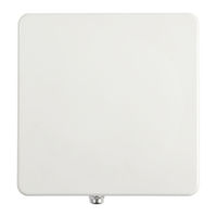
Cambium Networks PMP 450 Configuration And User's Manual (196 pages)
outdoor access point
Brand:
Cambium Networks
| Category:
Wireless Access Point
| Size: 3 MB
Table of Contents
Safety and Regulatory Information
3
Table of Contents
7
About this Configuration and User Guide
14
General Information
15
Version Information
15
Contacting Cambium Networks
15
Problems and Warranty
17
Security Advice
19
Warnings, Cautions, and Notes
20
Caring for the Environment
21
Chapter 1: Legal Information
23
Cambium Networks End User License Agreement
24
Acceptance of this Agreement
24
Definitions
24
Grant of License
24
Conditions of Use
25
Title and Restrictions
26
Confidentiality
26
Right to Use Cambium's Name
27
Transfer
27
Updates
27
Maintenance
27
Disclaimer
28
Limitation of Liability
28
U.S. Government
29
Term of License
29
Governing Law
29
Assignment
29
Survival of Provisions
30
Entire Agreement
30
Hardware Warranty
31
Limit of Liability
32
Chapter 2: Configuration and Alignment
33
Preparing for Configuration and Alignment
34
Safety Precautions During Configuration and Alignment
34
Regulatory Compliance During Configuration and Alignment
34
Task 1: Connecting to the Unit
35
Configuring the Management PC
35
Connecting to the PC and Powering up
37
Logging into the Web Interface
37
Task 2: Configuring IP and Ethernet Interfaces
38
Configuring the AP IP Interface
38
Table 1 IP Interface Attributes
40
NAT Tab of the SM with NAT Disabled
42
Figure 1 NAT Tab of the SM with NAT Disabled
42
Table 2 SM DNS Options with NAT Disabled
43
Table 3 SM with NAT Disabled - NAT Attributes
43
IP Tab of the SM with NAT Disabled
46
Figure 2 IP Tab of the SM with NAT Disabled
46
Table 4 SM with NAT Disabled - IP Attributes
46
NAT Tab of the SM with NAT Enabled
48
Figure 3 NAT Tab of the SM with NAT Enabled
48
Table 5 SM DNS Options with NAT Enabled
49
Table 6 SM with NAT Enabled - NAT Attributes
49
IP Tab of the SM with NAT Enabled
53
Reconnecting to the Management PC
53
Figure 4 IP Tab of SM with NAT Enabled
53
Table 7 SM with NAT Enabled - IP Attributes
53
VLAN Tab of the AP
54
Figure 5 VLAN Tab of the AP
54
Table 8 SM with NAT Enabled - IP Attributes
54
VLAN Membership Tab of the AP
58
Table 9 VLAN Membership Tab of the AP
58
Table 10 AP VLAN Membership Attributes
58
VLAN Tab of the SM
59
Table 11 VLAN Tab of the SM
59
Table 12 SM VLAN Attributes
59
VLAN Membership Tab of the SM
63
Figure 6 VLAN Membership Tab of the SM
63
Pppoe Tab of the SM
64
Table 13 SM VLAN Membership Attributes
64
Table 14 Pppoe Tab of the SM
64
Table 15 SM Pppoe Attributes
65
NAT Port Mapping Tab of the SM
68
Table 16 NAT Port Mapping Tab of the SM
68
Table 17 SM Pppoe Attributes
68
Task 3: Upgrading the Software Version and Using CNUT
69
Checking the Installed Software Version
69
Upgrading to a New Software Version
69
Task 4: Configuring General and Unit Settings
73
General Tab of the AP
73
Table 18 General Tab of the AP
73
Table 19 SM Pppoe Attributes
74
Unit Settings Tab of the AP
78
Table 20 Unit Settings Tab of the AP
78
Table 21 AP Unit Settings Attributes
78
General Tab of the SM
79
Table 22 General Tab of the SM
79
Table 23 AP Unit Settings Attributes
79
Unit Settings Tab of the SM
83
Table 24 Unit Settings Tab of the SM
83
Table 25 SM Unit Settings Attributes
84
Time Tab of the AP
85
Table 26 Unit Settings Tab of the SM
85
Table 27 AP Time Attributes
85
Task 5: Configuring Security
88
Isolating Aps from the Internet
88
Encrypting Radio Transmissions
89
Managing Module Access by Passwords
90
Figure 7 General Status Tab View for GUEST-Level Account
91
Figure 8 SM Add User Tab
91
Figure 9 Delete User Tab of the SM
92
Requiring SM Authentication
93
Figure 10 RJ-11 Pinout for the Override Plug
93
Filtering Protocols and Ports
94
Figure 11 Categorical Protocol Filtering
95
Figure 12 Ports Filtered Per Protocol Selection
95
Encrypting Downlink Broadcasts
96
Isolating Sms
96
Filtering Management through Ethernet
97
Allowing Management Only from Specified IP Addresses
97
Configuring Management IP by DHCP
97
Denying All Remote Access
97
Reinstating Remote Access Capability
98
Security Tab of the AP
99
Figure 13 Security Tab of the AP
99
Table 28 AP Security Attributes
100
Protocol Filtering Tab of the AP
102
Table 29 Protocol Filtering Tab of the AP
102
Table 30 AP Protocol Filtering Attributes
102
Port Configuration Tab of the AP
103
Table 31 Port Configuration Tab of the AP
103
Table 32 AP Port Configuration Attributes
103
Security Tab of the SM
104
Table 33 Security Tab of the SM
104
Table 34 AP Security Attributes
105
Protocol Filtering Tab of the SM
108
Table 35 Protocol Filtering Tab of the SM
108
Table 36 AP Protocol Filtering Attributes
108
Figure 14 Port Configuration Tab of the SM
109
Port Configuration Tab of the SM
109
Table 37 SM Port Configuration Attributes
110
Task 6: Configuring Radio Parameters
111
Figure 15 Radio Tab of the AP
111
Table 38 AP Radio Attributes
111
Table 39: Control Slot Settings for All OFDM Aps in Cluster
117
Table 40 Radio Tab of SM
120
Table 41 SM Radio Attributes
120
Task 7: Setting up SNMP Agent
124
SNMP Tab of the AP
125
Table 42 SNMP Tab of the AP
125
Table 43 AP SNMP Attributes
126
SNMP Tab of the SM
128
Table 44 SNMP Tab of SM
128
Table 45 SM SNMP Attributes
129
Task 8: Configuring Syslog
132
Configuring AP System Logging (Syslog)
132
Figure 16 AP Syslog Configuration Page
132
Configuring SM System Logging (Syslog)
133
Figure 17 SM Syslog Configuration Page
133
Table 46 Syslog Configuration Attributes
133
Table 47 Syslog Configuration Attributes
133
Task 9: Configuring Remote Access
134
Configuring SM IP Over-The-Air Access
134
Accessing SM Over-The-Air by LUID
134
Figure 18 SM IP Configuration Page
134
Denying All Remote Access
135
Figure 19 AP Session Status Page
135
Figure 20 AP Remote Subscribers Page
135
Reinstating Remote Access Capability
136
Task 10: Monitoring the AP-SM Link
137
Monitoring the AP-SM Link
137
Figure 21 AP Session Status Page
137
Task 11: Configuring Quality of Service
138
Maximum Information Rate (MIR) Parameters
138
Token Bucket Algorithm
138
MIR Data Entry Checking
139
Committed Information Rate
139
Figure 22 Uplink and Downlink Rate Caps Adjusted to Apply Aggregate Cap
139
Figure 23 Uplink and Downlink Rate Cap Adjustment Example
139
Bandwidth from the SM Perspective
140
Interaction of Burst Allocation and Sustained Data Rate Settings
140
High-Priority Bandwidth
140
Traffic Scheduling
141
Table 48 Characteristics of Traffic Scheduling
141
Setting the Configuration Source
142
Table 49 Recommended Combined Settings for Typical Operations
143
Table 50 Where Feature Values Are Obtained for an SM with Authentication Required
144
Table 51 Where Feature Values Are Obtained for an SM with Authentication Disabled
144
Quality of Service (Qos) Tab of the AP
145
Figure 24 Quality of Service (Qos) Tab of the AP
145
Table 52 AP Qos Attributes
145
Table 53 Broadcast Downlink CIR Achievable Per Broadcast Repeat Count
147
Diffserv Tab of the AP
148
Figure 25 Diffserv Tab of the AP
148
Table 54 AP Diffserv Attributes
148
Quality of Service (Qos) Tab of the SM
150
Figure 26 Quality of Service (Qos) Tab of the SM
150
Table 55 AP Quality of Service Attributes
150
Diffserv Tab of the SM
152
Figure 27 Diffserv Tab of the SM
152
Table 56 SM Diffserv Attributes
153
Task 12: Configuring a RADIUS Server
154
Understanding RADIUS for PMP 450
154
Choosing Authentication Mode and Configuring for Authentication Servers - AP
155
SM Authentication Mode - Require RADIUS or Follow AP
156
Figure 28 Security Tab of the AP
156
Figure 29 Security Tab of the SM
157
Handling Certificates
158
Configuring Your RADIUS Servers for SM Authentication
159
Figure 30 SM Certificate Management
159
Figure 31 AP Display of RADIUS Accept for SM
160
Configuring Your RADIUS Server for SM Configuration
161
Figure 32 AP Display of RADIUS Rejected SM
161
Figure 33 SM Display of RADIUS Accpet
161
Table 57 RADIUS Vendor Specific Attributes (Vsas)
162
Using RADIUS for Centralized AP and SM User Name and Password Management
163
Figure 34 User Authentication Tab of the AP
164
RADIUS Device Data Accounting
166
Figure 35 User Authentication Tab of the SM
166
Table 58 Device Data Accounting RADIUS Attributes
166
Table 59 RADIUS Accounting Messages Configuration
169
Table 60 RADIUS Data Accounting Message Interval
169
RADIUS Device Re-Authentication
170
RADIUS Attribute Framed-IP-Address
170
Table 61 Device Re-Authentication Configuration
170
Chapter 3: Reference Information
173
FCC and ICC Information
174
Table 62 US FCC Ids and Industry Canada Certification Numbers and Covered Configurations
174
Transmitter Output Power
177
Table 63 PMP 450 AP Transmitter Output Power
177
Exposure Separation Distances
179
Details of Exposure Separation Distances Calculations and Power Compliance Margins
179
Table 64 Exposure Separation Distances
179
Table 65 Calculated Exposure Distances and Power Compliance Margins
180
Appendix A: Glossary
181
Advertisement
Advertisement
Related Products
Cambium Networks PMP 450 Series
Cambium Networks PMP 430 Series
Cambium Networks PMP 450i
Cambium Networks PMP 450 AP
Cambium Networks PMP 450 SM
Cambium Networks PMP 450b
Cambium Networks PMP 450i AP
Cambium Networks PMP 450i SM
Cambium Networks PMP 400 Series
Cambium Networks PMP 450 MicroPoP
Cambium Networks Categories
Wireless Access Point
Network Hardware
Network Router
Switch
Wireless Router
More Cambium Networks Manuals
Login
Sign In
OR
Sign in with Facebook
Sign in with Google
Upload manual
Upload from disk
Upload from URL