
Subscribe to Our Youtube Channel
Related Manuals for Elba N96 EX 939 S


Summary of Contents for Elba N96 EX 939 S
- Page 1 Instructions for the use - Installation advices GLASS CERAMIC COOKER ELBA QUALITY MADE IN ITALY H O M E A P P L I A N C E S Made in Italy...
- Page 2 Dear Customer, Thank you for having purchased and given your preference to our product. The safety precautions and recommendations reported below are for your own safety and that of others. They will also provide a means by which to make full use of the features offered by your appliance.
-
Page 3: Important Safety Precautions And Recommendations
IMPORTANT SAFETY PRECAUTIONS AND RECOMMENDATIONS IMPORTANT: This appliance is designed and manufactured solely for the cooking of domestic (household) food and is not suitable for any non domestic application and therefore should not be used in a commercial environment. The appliance guarantee will be void if the appliance is used within a non domestic environment i.e. - Page 4 • Do not use a steam cleaner because the moisture can get into the appliance thus make it unsafe. • Do not touch the appliance with wet or damp hands (or feet). • Do not use the appliance whilst in barefoot. • If you should decide not to use this appliance any longer (or decide to substitute another model), before disposing of it, it is recommended that it be made inoperative in an appropriate...
- Page 5 • Make sure that electrical cables connecting other appliances in the proximity of the cooker cannot come into contact with the hob or become entrapped in the oven door. • WARNING: Unattended cooking on a hob with fat or oil can be dangerous and may result in fire.
- Page 6 • Do not line the oven walls with aluminium foil. Do not place baking trays or the drip tray on the base of the oven chamber. • FIRE RISK! Do not store flammable material in the oven or in the storage compartment.
-
Page 7: Cooking Hob
COOKING HOB Fig. 1.1 VITROCERAMIC COOKING HOB 3 circuit cooking zone Ø 180 mm 1700 W 3 circuit cooking zone Ø 145 mm 1200 W Oval double cooking zone Ø 145 x 250 mm 1800/1000 W Double cooking zone Ø 210/120 mm 2100/700 W 3 circuit cooking zone Ø... -
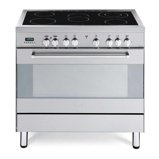
Page 8: Control Panel
CONTROL PANEL Fig. 2.1 CONTROLS DESCRIPTION Electronic programmer Multifunction oven switch knob Multifunction oven thermostat knob Front left cooking zone control knob Rear left cooking zone control knob Central cooking zone control knob Rear right cooking zone control knob Front right cooking zone control knob Rotisserie control knob Pilot lamps: 10. - Page 9 USE OF VITROCERAMIC HOB IMPORTANT NOTE: The ceramic surface of the hob allows a fast transmission of heat in the vertical heating elements incorporate direction, from the heating elements thermolimiter that switches ON/OFF the underneath the ceramic glass to the pans element in all settings to protect any set on it.
-
Page 10: Double Zone
DOUBLE AND OVAL RADIANT ZONES The heating element is formed of a coil of resistant material which reaches the working temperature quickly. Operation of the cooking zone is controlled by a continuous energy regulator from “1” to “12” (maximum temperature) (fig. 3.3). To turn on both zones of the double element, turn the double element knob fully clockwise to the position... -
Page 11: Cooking Hints
COOKING HINTS Cooking plate Cooking plate controlled by a 12 controlled by a 7 K nob TYPE OF COOKING position energy s etting position switch regulator Switched OFF For melting operations (butter, chocolate). To maintain food hot and to hea t sma ll quantities of liquid (sauces , eggs ). - Page 12 RESIDUAL HEAT INDICATOR Caution! The hob also features 5 warning lights the cooking hob becomes very hot which are connected to the corresponding during operation. plates. Keep children well out of reach. When the temperature of a cooking plate is above 60°C, the relevant warning light will COOKING HINTS: also light up to warn of heat on the surface...
- Page 13 ADVICE FOR SAFE USE OF THE CLEANING COOKTOP Before you begin cleaning make sure • Before switching on make sure that you that the appliance is switched off. have the correct knob for the hotplate Remove any encrustation using a scraper chosen.
-
Page 14: Multifunction Electric Oven
MULTIFUNCTION ELECTRIC OVEN OPERATING PRINCIPLES Attention: the oven door becomes Heating cooking very hot during operation. MULTIFUNCTION oven are obtained in the Keep children away. following ways: a. by normal convection The heat is produced by the upper and lower heating elements. GENERAL FEATURES As its name indicates, this is an oven b. -
Page 15: Thermostat Knob
Fig. 4.1 Fig. 4.2 THERMOSTAT KNOB This only sets the cooking temperature and does not switch the oven on. Rotate clockwise until the required temperature is reached (from 50 to 225°C). The temperature indicator light signals when the heating elements are switched on or switched off. -
Page 16: Defrosting Frozen Foods
GRILLING The infra-red heating element is switched on. The heat is diffused by radiation. Use with the oven door closed and the thermostat knob to between 50 and 225°C for 15 minutes, then to position 175°C. Note: It is recommended that you do not grill for longer than 30 minutes at any one time. Attention: the oven door becomes very hot during operation. -
Page 17: Cooking Advice
THAWING AND WARMING UP The upper element and the circular element connected in series, are switched on; also the fan is on. The heat is diffused by forced convection with the most heat being produced by the upper element. The temperature must be regulated between 50 and 140°C with the thermostat knob. Recommended for: To keep foods hot after cooking. -
Page 18: Grilling And Cooking Au Gratin
SIMULTANEOUS COOKING OF DIFFERENT FOODS The MULTI-FUNCTION oven set on position gives simultaneous heterogeneous cooking of different foods. Different foods such as fish, cake and meat can be cooked together without mixing the smells and flavours. This is possible since the fats and vapors are oxidized while passing through the electrical element and therefore are not deposited onto the foods. - Page 19 ROTISSERIE USE OF THE ROTISSERIE This device is made up of: • Insert the tray into the lowest rack • an electrical motor mounted on the holders of the oven and insert the rear part of the oven rod support into the intermediate rack •...
-
Page 20: Electronic Programmer
ELECTRONIC PROGRAMMER The electronic programmer is a device which groups together the following functions: • 24 hours clock with illuminated display • Timer (up to 23 hours and 59 minutes) • Program for automatic oven cooking • Program for semi-automatic oven cooking Description illuminated Description of the buttons:... -
Page 21: Electronic Clock
ELECTRONIC CLOCK ELECTRONIC TIMER (fig. 5.2) The programmer is equipped with an The timer program consists only of a electronic clock with illuminated numbers buzzer which may be set for a maximum which indicates hours and minutes. period of 23 hours and 59 minutes. Upon immediate connection of the oven or If the AUTO symbol is flashing push the after a power cut, three zeros will flash on... -
Page 22: Automatic Oven Cooking
AUTOMATIC OVEN COOKING Set the temperature and the cooking program by using the switch and To cook food automatically in the oven, it is thermostat knobs of the oven (see necessary to: specific chapters). Set the length of the cooking period. oven programmed Set the end of the cooking time. -
Page 23: Semi-Automatic Cooking
SEMI-AUTOMATIC COOKING At the end of the cooking time the oven will turn off automatically, the symbol This is used to automatically switch off the will turn off, AUTO will flash and a buzzer oven after the desired cooking time has will be sound, which can be turned off by elapsed. -
Page 24: Cleaning And Maintenance
CLEANING AND MAINTENANCE GENERAL ADVICE STAINLESS STEEL, ALUMINIUM PARTS • Before you begin cleaning, you must AND SILK-SCREEN PRINTED SURFACES ensure that the appliance is switched Clean using an appropriate product. off. Always dry thoroughly. • It is advisable to clean when the IMPORTANT: these parts must be cleaned appliance is cold and especially when very carefully to avoid scratching and... -
Page 25: Oven Floor
REPLACING THE OVEN LIGHT BULB Fig. 6.1 Switch the cooker off at the mains. When the cooker is cool unscrew and replace the bulb with another one resistant to high temperatures (300°C), voltage 230V 50 Hz, type E14 and same power (check watt power as stamped in the bulb itself) of the replaced bulb. -
Page 26: Storage Compartment
Fig. 6.4 Fig. 6.5 STORAGE COMPARTMENT OVEN DOOR The storage compartment is accessible The internal glass panel can be easily through the pivoting panel (fig. 6.5). removed for cleaning by unscrewing the 4 retaining screws (fig. 6.4). Do not use harsh abrasive cleaners or Do not store flammable material in the sharp metal scrapers to clean the oven oven or in the storage compartment. -
Page 27: Removing The Oven Door
REMOVING THE OVEN DOOR The oven door can easily be removed as follows: • Open the door to the full extent (fig. 6.6a). • Open the lever “A” completely on the left and right hinges (fig. 6.6b). • Hold the door as shown in fig. 6.6. •... - Page 28 Advice for the installer IMPORTANT • Cooker installation must only be carried out by QUALIFIED TECHNICIANS and in compliance with local safety standards. The appliance must be installed in compliance with regulations in force in your country and in observation of the manufacturer’s instructions.
-
Page 29: Installation
INSTALLATION LOCATION The cooker must be installed by a qualified technician and in compliance with the local safety standards. The appliance must be kept no less than 50 mm away from any side wall which exceed the height of the hob surface (fig. 7.1). The appliance must be housed in heat resistant units. The walls of the units must be capable of resisting temperatures of 75°C above room temperature. - Page 30 FITTING THE ADJUSTABLE FEET AND LEVELLING THE COOKER The adjustable feet must be fitted to the base of the cooker before use (fig. 7.2). Rest the rear of the cooker on a piece of the polystyrene packaging exposing the base for the fitting of the feet. Fit the 4 legs by screwing them tight into the support base as shown in figure 7.3 Fig.
-
Page 31: Moving The Cooker
MOVING THE COOKER Fig. 7.5 WARNING: When raising cooker to upright position always ensure two people carry out this manoeuvre to prevent damage to the adjustable feet (fig. 7.5). WARNING Be carefull: DO NOT LIFT the cooker by the door handle when raising to the upright position (fig. -
Page 32: Anti-Tilt Bracket
ANTI-TILT BRACKET Important! To restrain the appliance and prevent it tipping accidentally, fit a bracket to its rear to fix it securely to the wall. To fit the anti-tilt bracket: After you have located where the cooker is to be positioned, mark on the wall the place where the two screws of the anti-tilt bracket have to be fitted. Please follow the indications given in fig. 7.9. Drill two 8 mm diameter holes in the wall and insert the plastic plugs supplied. -
Page 33: Electrical Section
ELECTRICAL SECTION N.B. For connection to the mains, do IMPORTANT: The cooker must be not use adapters, reducers or branching installed accordance with devices as they can cause overheating manufacturer’s instructions. and burning. Incorrect installation, which manufacturer accepts If the installation requires alterations to the responsibility, may cause damage to domestic electrical system, call an expert. - Page 34 CONNECTING THE FEEDER CABLE FEEDER CABLE SECTION “TYPE H05RR-F” To connect the feeder cable to the cooker it is necessary to: 230 V ac 3 x 6 mm (**) • Remove the two screws that hold shield “A” behind the cooker (fig. 8.1). 230 V 3 ac 4 x 4 mm (**)
- Page 35 230 V~ 230 V 3~ 400 V 2N~ 400 V 3N~ Fig. 8.3...
- Page 36 The manufacturer reserves the right to make all modifications to its products deemed necessary for manufacturer commercial reasons at any moment and without prior notice, without jeopardising the essential functional and safety characteristics of the appliances. www.elba-cookers.it H O M E A P P L I A N C E S Made in Italy...
Need help?
Do you have a question about the N96 EX 939 S and is the answer not in the manual?
Questions and answers