Table of Contents
Advertisement
Quick Links
Advertisement
Table of Contents

Related Manuals for Elba EC 967F SS


Summary of Contents for Elba EC 967F SS
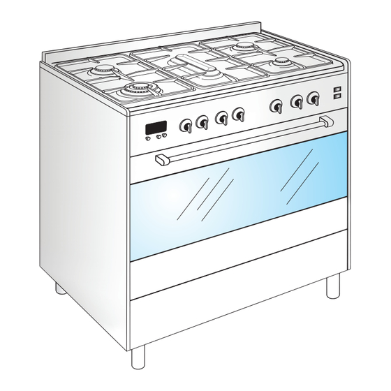
- Page 1 Model EC 967F SS COOKER COOKER COOKER COOKER...
- Page 2 Dear Customer, IMPORTANT INSTRUCTIONS AND A D V I C E F O R T H E U S E O F We thank you very much for choosing ELECTRICAL APPLIANCES our products. The instructions and advice included in The use of any electrical appliance requires this booklet are given to safeguard your the compliance with some basic rules, safety and to use this appliance correctly.
-
Page 3: Important Precautions And Recommendations
IMPORTANT PRECAUTIONS AND RECOMMENDATIONS Make sure that electrical cables After having unpacked the appliance, connecting other appliances in the check to ensure that it is not damaged proximity of the cooker cannot come into and that the oven door closes correctly. contact with the hob or become In case of doubt, do not use it and consult entrapped in the oven door. -
Page 4: Cooking Hob
1 - COOKING HOB - CONTROL PANEL Note: The gas burners are fitted with safety valves device which stop the gas flow if the flame should go out. Fig. 1.1a COOKING HOB 1. Double-ring burner (PB) 3,45 kW 2. Semi-rapid burner (SR) 1,90 kW 3. -
Page 5: Use Of The Cooking Hob
2 - USE OF THE COOKING HOB GAS BURNERS Each burner is controlled by a gas tap assuring the opening and the closing of the gas supply. Turning the knob so that the indicator line points to the symbols printed on the panel achieves the following functions: - symbol : off... -
Page 6: Important Note
LIGHTING GAS BURNERS FITTED IMPORTANT NOTE: The device shall not be operated for WITH SAFETY VALVE DEVICE more than 15 seconds. If after 15 To ignite the burners, the following seconds the burner has not lit, stop instructions are to be followed: operating the device and wait at least 1 minute before attempting a further Press in the corresponding knob and turn... - Page 7 CHOICE OF THE BURNER CORRECT USE OF THE On the control panel, near every knob, there DOUBLE-RING BURNER is a diagram that indicates which burner is controlled by that knob. The flat-bottomed pans are to be placed The suitable burner must be chosen directly onto the pan-support.
-
Page 8: Multifunction Electric Oven
3 - MULTIFUNCTION ELECTRIC OVEN ATTENTION: the oven door becomes OPERATING PRINCIPLES very hot during operation. Keep children away. Heating and cooking in the MULTI- Models with lid: The cooker lid must be FUNCTION oven are obtained in the kept open when the multifunction following ways: electric oven is in use. - Page 9 Fig. 3.1a Fig. 3.1b THERMOSTAT KNOB (Fig. 3.1b) This only sets the cooking temperature and GRILLING does not switch the oven on. Rotate clockwise until the required temperature is The infra-red heating element is switched reached (from 50 to 225°C). on.
-
Page 10: Hot Air Cooking
requires about one hour. The defrosting M A I N T A I N I N G times vary according to the quantity and T E M P E R A T U R E A F T E R type of foods to be defrosted. -
Page 11: Cooking Advice
to remember: COOKING ADVICE that it is advisable to maintain a tem- perature between 180 and 200 °C. STERILIZATION that the cooking time depends on the Sterilization of foods to be conserved, in full quantity and the type of foods. and hermetically sealed jars, is done in the following way: S I M U L TA N E O U S C O O K I N G O F... - Page 12 COOKING ADVICE ROTISSERIE (fig. 3.2) For the consumer’s information, the This device is made up of: following table gives some dishes with their relative cooking temperatures in °C. an electrical motor mounted on the rear The cooking time varies with the quantity. part of the oven stainless steel spit with a removable DISHES...
-
Page 13: Safety Guard
USE OF THE ROTISSERIE Attention: the oven door becomes very hot during operation. Keep children Very important: the rotisserie must away. always be used with the oven door It is recommended that you do not grill closed. for longer than 30 minutes at any one time. -
Page 14: Electronic Clock
4 - ELECTRONIC CLOCK / END COOKING TIMER The electronic clock / end cooking timer is a device with the following functions: 24 hours clock with illuminated display; Timing of oven cooking with automatic switch-off (max. 99 minutes). ELECTRONIC CLOCK Upon immediate connection of the cooker or after a mains failure, three zeros will flash on the programmer panel. -
Page 15: Cleaning And Maintenance
5 - CLEANING AND MAINTENANCE GENERAL ADVICE When the appliance is not being used, it is advisable to keep the gas tap closed. Every now and then check to make sure that the flexible tube that connects the gas line or the gas cylinder to the appliance is in perfect condition and eventually substitute it if it shows signs of wearing or damage. -
Page 16: Glass Lid
Models with glass lid Do not close the cooker lid when the REGULATING OF THE BALANCE burners or electric plates are still hot and Lower the lid and check the correct balance. when the oven is on or still hot. While opened at 45°... -
Page 17: Assembling The Backguard
Models with BACKGUARD ASSEMBLING THE BACKGUARD Please note that : Before assembling remove any protective film/adhesive tape. The backguard “B” can be found packed on the cooktop. Check that the side supports “S” and “D” are correctly mounted in the backguard as indicated in the picture. -
Page 18: Replacing The Oven Light Bulb
CLEANING BURNERS All the enamelled parts must be cleaned They can be removed and washed only with with a sponge and soapy water or other a soapy water. non-abrasive products. Detergents can be used but must not be Dry preferably with a soft cloth. abrasive or corrosive. -
Page 19: Storage Compartment
Fig. 5.4 Fig. 5.5 OVEN DOOR STORAGE COMPARTMENT The internal glass panel can be easily The storage compartment is accessible removed for cleaning by unscrewing the 4 through the pivoting panel (fig. 5.5). retaining screws (fig. 5.4). Do not store flammable material in the oven or in the storage compartment. -
Page 20: Oven Floor
ASSEMBLY AND DISMANTLING OF THE SIDE RUNNER FRAMES Fit the side runner frames into the holes on the side walls inside the oven (fig.5.6). Slide the tray and rack into the runners. To dismantle, operate in reverse order. OVEN FLOOR The oven floor “F”... -
Page 21: Removing The Oven Door
REMOVING THE OVEN DOOR Fig. 5.8A The oven door can be easily removed as follows: Open the door to the full extent (fig. 5.8A). Attach the retaining rings to the hooks on the left and right hinges (fig.5.8B). Hold the door as shown in fig. 5.8. Gently close the door and withdraw the lower hinge pins from their location (fig. -
Page 22: Advice For The Installer
ADVICE FOR INSTALLER IMPORTANT Cooker installation, regulation and conversion to other gas types must only be carried out by QUALIFIED TECHNICIANS and in compliance with local safety standards. Failure to observe this rule will invalidate the warranty. The electrical mains outlet, if located behind the cooker, must not be higher than 18 cm above the floor level Some appliances are supplied with a protective film on steel and aluminium parts. -
Page 23: Installation
6 - INSTALLATION INSTALLATION This cooker has class “2/1” overheating protection so that it can be installed next to a cabinet. The cooker must be kept no less than 50 mm away from any side wall which exceed the height of the cooktop. -
Page 24: Fitting The Adjustable Feet
FITTING THE ADJUSTABLE FEET The adjustable feet must be fitted to the base of the cooker before use. Rest the rear of the cooker an a piece of the polystyrene packaging exposing the base for the fitting of the feet. Fit the 4 legs by screwing them tight into the support base as shown in pictures 6.2-6.3- Fig. -
Page 25: Levelling The Cooker
WARNING When raising cooker to upright position always ensure two people carry out this manoeuvre to prevent damage to the adjustable feet (fig. 6.5). WARNING Be careful: DO NOT LIFT the cooker by the door handle when raising to the upright position (fig. - Page 26 C H O O S I N G S U I T A B L E SURROUNDINGS In the room chosen to accommodate the Extractor hood Extractor hood gas appliance, there must be an adequate for products of for products of natural draft to allow combustion of the gas.
-
Page 27: Gas Section
7 - GAS SECTION INSTALLATION GAS CONNECTION The gases used for the operation of cooking The connection must be executed by a appliances may be grouped by their qualified technician according to the characteristics into three types: relevant standards. (Natural Gas) Ensure that the room in which the cooker is G30/ G31 (L.P.G.) to be installed is adequately ventilated, in... - Page 28 The fitting (fig. 7.3) is made up of: they are not squashed, and do not A - Gas train terminal fitting (rh or lh) come into contact with moving parts. B - Adapter for G20 and Town gas The seals “D” and “E” (fig. 7.3) are C - Adapter for G30/G31 the elements that guarantee the seal D - Gasket...
- Page 29 REPLACEMENT OF TOP BURNER INJECTORS Note: if the injectors are not supplied with the appliance they can be obtained from the “Service Centre”. To replace the injectors, raise the cooktop in the following manner: Remove the pan-supports and burners from the cooktop. Fig.
-
Page 30: Injectors Replacement
INJECTORS REPLACEMENT Fully raise the adjusting air tube A (fig. 7.6) in order to easily reach the injector. By an angle 7 spanner, remove the injector from its housing and replace it by the proper one according to the kind of gas (see “TABLE FOR THE CHOICE OF THE INJECTORS”). -
Page 31: Adjusting Of The Minimum Of The Top Burners
ADJUSTING OF THE MINIMUM OF ATTENTION: THE TOP BURNERS After regulating the burners, replace the In passing from one type of gas to another, cooktop by repeating the steps the gas flow must also be changed, described above in reverse order. Be considering that in this position the flame especially careful not to confuse the must have a length of about 4 mm and must... - Page 32 TABLE FOR THE CHOICE OF THE INJECTORS BURNERS MEASURED MANUFACTURER’S BY-PASS ø RING HEAT INPUT (kW) DECLARATION (kW) INJECTOR OPENING [1/100 mm] [1/100 mm] [mm] NOMINAL REDUCED NOMINAL REDUCED AUXILIARY(A) 0,95 0,45 1,00 0,30 SEMI-RAPID (SR) - Rear right 1,76 0,98 1,90 0,38...
- Page 33 INCREASE OF AIR NECESSARY FOR GAS COMBUSTION (2 m /h x kW) BURNERS AIR NECESSARY FOR COMBUSTION [m /h] AUXILIARY(A) 2,00 SEMI-RAPID (SR) 3,80 DOUBLE-RING 6,90 FISH (PE) 7,10...
-
Page 34: Electrical Section
8 - ELECTRICAL SECTION IMPORTANT: N.B. For connection to the mains, do not use adapters, reducers or branching The cooker must be installed in devices as they can cause overheating accordance with the manufacturer’s and burning. instructions. Incorrect installation, for which the If the installation requires alterations to the manufacturer accepts no responsibility, domestic electrical system call an expert. - Page 35 E L E C T R I C A L F E E D E R C A B L E FEEDER CABLE SECTION TYPE CONNECTION H05RR-F To connect the supply cable: 230 V ~ 3 x 1,50 mm Remove the screws securing the cover “A”...
- Page 36 The manufacturer cannot be held responsible for possible inaccuracies due to printing or transcription errors in the present booklet. The manufacturer reserves the right to make all modifications to its products deemed necessary for manufacture or commercial reasons at any moment and without prior notice, without jeopardising the essential functional and safety characteristics of the appliances.
Need help?
Do you have a question about the EC 967F SS and is the answer not in the manual?
Questions and answers