Table of Contents
Advertisement
User Guide OI/FET100–EN Rev. A
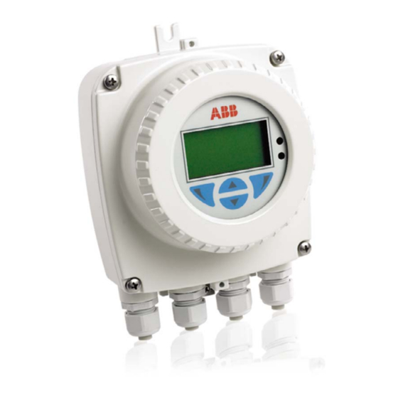
WaterMaster FET100
Electromagnetic flowmeter
Transmitter
The perfect fit for all water
industry applications
Introduction
WaterMaster™ is a range of high performance
electromagnetic flowmeters for the measurement of
electrically-conductive fluids and systems are normally
supplied factory-configured and calibrated.
This User Guide provides installation, connection,
security, start-up and basic setup details. For
programming and configuration information refer to the
Programming Guide – IM/WMP.
This User Guide should be used in conjunction with the
following publications:
–
Programming Guide – IM/WMP
–
User Guide Supplement, PROFIBUS RS485 Physical
Layer (FEX100–DP) – IM/WMPBS–EN
–
User Guide Supplement, PROFIBUS FEX100-DP
Parameter Tables – IM/WMPBST–EN
–
User Guide Supplement, MODBUS RS485 Physical
Layer (FEX100–MB) – COI/FEX100/MOD–EN
–
User Guide Supplement, MODBUS Tables –
COI/FEX100/MOD/TBL–EN
Advertisement
Table of Contents

Related Manuals for ABB WaterMaster FET100


Summary of Contents for ABB WaterMaster FET100
- Page 1 User Guide OI/FET100–EN Rev. A WaterMaster FET100 Electromagnetic flowmeter Transmitter The perfect fit for all water industry applications Introduction WaterMaster™ is a range of high performance This User Guide should be used in conjunction with the electromagnetic flowmeters for the measurement of...
- Page 2 We are an established world force in the design and manufacture of instrumentation for industrial process control, flow measurement, gas and liquid analysis and environmental applications. As a part of ABB, a world leader in process automation technology, we offer customers application expertise, service and support worldwide.
-
Page 3: Table Of Contents
WaterMaster FET100 Electromagnetic floweter | Transmitter Safety ............................... 2 Electrical Safety ............................. 2 Symbols ................................ 2 Health & Safety ............................. 3 Mechanical Installation ........................4 Installation Conditions ........................... 4 Dimensions ..............................6 Electrical Installation ........................8 Remote Transmitter / Sensor Arrangement ....................8 Transmitter Terminal Connections ....................... -
Page 4: Safety
WaterMaster FET100 Electromagnetic floweter | Transmitter 1 Safety 1 Safety Information in this manual is intended only to assist our customers in the efficient operation of our equipment. Use of this manual for any other purpose is specifically prohibited and its contents are not to be reproduced in full or part without prior approval of the Technical Publications Department. -
Page 5: Health & Safety
WaterMaster FET100 Electromagnetic floweter | Transmitter 1 Safety 1.3 Health & Safety Health and Safety To ensure that our products are safe and without risk to health, the following points must be noted: The safety requirements of this equipment, any associated equipment and the local environment must be taken into consideration during installation. -
Page 6: Mechanical Installation
WaterMaster FET100 Electromagnetic floweter | Transmitter 2 Mechanical Installation 2 Mechanical Installation 2.1 Installation Conditions Allow room to read display Fig. 2.1 Siting 60 °C (140 °F) Max. –20 °C (–40 °F) Min. Fig. 2.2 Within Temperature Limits Fig. 2.3 Shade... - Page 7 WaterMaster FET100 Electromagnetic floweter | Transmitter 2 Mechanical Installation Fig. 2.4 Vibration Fig. 2.5 Spillage Transmitter Submersion: 1 m (3.3 ft) <12 hours Accrued time IP67 (NEMA 4X) Fig. 2.6 Within Environmental Rating Position to enable access to display and communication connector Fig.
-
Page 8: Dimensions
WaterMaster FET100 Electromagnetic floweter | Transmitter 2 Mechanical Installation 2.2 Dimensions Dimensions in mm (in). 202.5 (8) – Standard Gland 98 (3.9) 250 (9.8) Armored Gland 118 (4.6) Fig. 2.8 Integral Transmitter Dimensions (Standard Gland Shown) OI/FET100–EN Rev. A... - Page 9 WaterMaster FET100 Electromagnetic floweter | Transmitter 2 Mechanical Installation 98 (3.9) R3.2 (0.1 ) 71 (2.8) Fig. 2.9 Remote Transmitter Dimensions (Standard Gland Shown) Note. Fix remote transmitter to a secure surface using 3 x M5 screws (not supplied). OI/FET100–EN Rev. A...
-
Page 10: Electrical Installation
WaterMaster FET100 Electromagnetic floweter | Transmitter 3 Electrical Installation 3 Electrical Installation 3.1 Remote Transmitter / Sensor Arrangement Note. For bonding connections use 4mm (< 10AWG) cable. Power Supply Fig. 3.1 Remote Transmitter in Roadside Cabinet – Flanged Sensor OI/FET100–EN Rev. A... - Page 11 WaterMaster FET100 Electromagnetic floweter | Transmitter 3 Electrical Installation Power Supply Fig. 3.2 Remote Transmitter in Roadside Cabinet – Probe Sensor OI/FET100–EN Rev. A...
-
Page 12: Transmitter Terminal Connections
WaterMaster FET100 Electromagnetic floweter | Transmitter 3 Electrical Installation 3.2 Transmitter Terminal Connections Warning. Isolate the transmitter from power supplies before removing the cover. Fig. 3.3 Accessing the Transmitter Terminals Referring to Fig. 3.3: 1. Slacken (but do not remove) the four transmitter cover screws 2. -
Page 13: Cable Preparation (Remote Systems Only)
WaterMaster FET100 Electromagnetic floweter | Transmitter 3 Electrical Installation Test Points for Output Connections AC/DC Power Sensor Supply Terminal Cable Terminal Output Connections Terminal Backplane Internal Earth Internal Earth (Alternative PE) (Alternative PE) External Earth Output Connections Power Cable Output Connections Sensor Cable Fig. -
Page 14: Transmitter / Sensor Cable Connections
WaterMaster FET100 Electromagnetic floweter | Transmitter 3 Electrical Installation 3.4 Transmitter / Sensor Cable Connections Caution. Make connections only as shown. Twist the screen wire of D1 / TFE + D2 with the outer screen drain wire and sleeve them. -
Page 15: Output Connections
WaterMaster FET100 Electromagnetic floweter | Transmitter 3 Electrical Installation 3.5 Output Connections Caution. Inductive loads must be suppressed or clamped to limit voltage swings. Operation of outputs is programmable. External isolators are not normally required as the pulse and alarm circuit is electrically separated from all other WaterMaster connections. -
Page 16: Alarm Outputs
WaterMaster FET100 Electromagnetic floweter | Transmitter 3 Electrical Installation 3.5.2 Alarm Outputs O/P3 Terminal connection IDs are HART- / PROFIBUS- / MODBUS- variant dependent Fig. 3.7 Alarm Output Connections 3.5.3 Current Output (4 to 20 mA) – HART (FEX100) Variant... -
Page 17: Rs485 Communications - Profibus (Fex100-Dp) And Modbus (Fex100-Mb) Variants
WaterMaster FET100 Electromagnetic floweter | Transmitter 3 Electrical Installation 3.5.4 RS485 Communications – PROFIBUS (FEX100-DP) and MODBUS (FEX100-MB) Variants PROFIBUS / MODBUS RS485 A1 / B1 – In A2 / B2 – Out Screen Clamp Fig. 3.9 WaterMaster RS485 Backplane Connections to PROFIBUS / MODBUS Networks 3.5.5 Test Point Access... -
Page 18: Power Supply Connections
WaterMaster FET100 Electromagnetic floweter | Transmitter 3 Electrical Installation 3.6 Power Supply Connections Warning. Electrical installation and earthing (grounding) must be in accordance with relevant national and local standards. Power must be connected via a suitable isolator and fused in accordance with relevant standards. -
Page 19: Dc (And Low Voltage Ac) Power Supply
WaterMaster FET100 Electromagnetic floweter | Transmitter 3 Electrical Installation 3.6.2 DC (and Low Voltage AC) Power Supply Power Supply Indicator LED *DC Fuse F2 2 A Type T (see table below for suppliers) Internal Earth Screws 2/– Black Green / Yellow External Earth >4 mm... -
Page 20: Configuration Dip Switches
WaterMaster FET100 Electromagnetic floweter | Transmitter 3 Electrical Installation 3.6.3 Configuration DIP Switches Three configuration DIP switches are mounted on the transmitter backplane board. These are factory-set as follows: Remote transmitter – all OFF Integral transmitter – SW3 ON For MID-compliant flowmeters set the read-only / MID protection switch to 'ON' to ensure the meter is secure from tampering. - Page 21 WaterMaster FET100 Electromagnetic floweter | Transmitter 3 Electrical Installation Referring to Fig. 3.14: 1. Confirm that the cartridge to be fitted is of the correct power supply and for the correct communications bus type (HART, PROFIBUS OR MODBUS) by checking the label...
-
Page 22: Start-Up And Operation
WaterMaster FET100 Electromagnetic floweter | Transmitter 4 Start-up and Operation 4 Start-up and Operation Note. This section describes the options available at the 'Easy Setup' menu. Refer to the Programming Manual (IM/WMP) for comprehensive details of all end-user menus and operating levels. -
Page 23: Start-Up Screens
WaterMaster FET100 Electromagnetic floweter | Transmitter 4 Start-up and Operation 4.2 Start-up Screens At start-up, the type of screen displayed indicates the status of the system. There are four common start-up screen types as follows: System Start-up System Startup At system start-up, a progress bar is displayed for the duration LOADING SYSTEM DATA of the start-up period. - Page 24 WaterMaster FET100 Electromagnetic floweter | Transmitter 4 Start-up and Operation Installation Changed System Startup If the sensor data stored in the transmitter memory does not INSTALLATION CHANGED match the data of the connected sensor, the warning Identify Changed Item 'INSTALLATION CHANGED' is displayed.
-
Page 25: Security Levels And Password Access
WaterMaster FET100 Electromagnetic floweter | Transmitter 4 Start-up and Operation 4.3 Security Levels and Password Access At power-up, the 'Start-up Display' and 'Process Display' screens are activated in sequence. Note. Passwords at 'Standard' and 'Advanced' level can be set and changed by end-users. -
Page 26: Default Passwords
Passwords can contain up to 5 characters and are not case sensitive. To prevent unauthorized access ABB recommend the default passwords are changed on commissioning. Note. When allocating passwords, record a copy of each password and store in a safe location. It is not possible to interrogate the transmitter to 'recover' passwords once they have been set. -
Page 27: Easy Setup
WaterMaster FET100 Electromagnetic floweter | Transmitter 4 Start-up and Operation 4.4 Easy Setup Easy Setup Menu The 'Easy Setup' level is used to set the system up quickly Easy Setup and contains a series of options for users with 'Standard' and 'Advanced' access permission. - Page 28 WaterMaster FET100 Electromagnetic floweter | Transmitter 4 Start-up and Operation Parameter Range [Default] Note Language English, Deutsch, Français, Español, [English] Selectable Italiano, Polski, Portuguese Q (Flowrate) Unit /s, m /min, m /h, m /d, ft /s, ft /min, /h] Selectable...
-
Page 29: Specification
WaterMaster FET100 Electromagnetic floweter | Transmitter 5 Specification 5 Specification Functional Specification Power supply Mains 85 to 265 V AC @ <7 VA Low voltage 24 V AC +10 %/–30 % @ <7 VA 24 V ±30 % @ <0.4 A... - Page 30 WaterMaster FET100 Electromagnetic floweter | Transmitter 5 Specification Temperature limitations Ambient temperature Remote transmitter –20 to 60 °C (–4 to 140 °F) Integral transmitter –20 to 60 °C (–4 to 140 °F) Typically <±10 ppm/°C @ Vel 0.5 mls Temperature coefficient...
- Page 31 Repair Centre. — Metals and Minerals — Oil, Gas & Petrochemical — Pulp and Paper ABB Limited Tel: +44 (0)1453 826661 Drives and Motors Fax: +44 (0)1453 829671 — AC and 6 Drives, AC and DC Machines, AC Motors to —...
- Page 32 With regard Stonehouse to purchase orders, the agreed particulars Gloucestershire GL10 3TA shall prevail. ABB does not accept any responsibility whatsoever for potential errors or possible lack of information in this Tel: +44 1453 826 661 document.
Need help?
Do you have a question about the WaterMaster FET100 and is the answer not in the manual?
Questions and answers