ABB 266HSH Operating Instructions Manual
2600t series pressure transmitters low power consumption (1... 5 v dc)
Hide thumbs
Also See for 266HSH:
- Operating instructions manual (96 pages) ,
- Instruction manual (47 pages)

Related Manuals for ABB 266HSH


Summary of Contents for ABB 266HSH
- Page 1 Operating Instruction OI/266/LowP-EN Rev.A 2600T Series Pressure Transmitters 266HSH Model Low Power Consumption (1... 5 V DC) Engineered solutions for all applications Measurement Made Easy...
- Page 2 We are an established world force in the design and manufacture of measurement products for industrial process control, flow measurement, gas and liquid analysis and environmental applications. As a part of ABB, a world leader in process automation technology, we offer customers application expertise, service and support worldwide.
-
Page 3: Table Of Contents
Contents Index 7 Commissioning ........... 17 1 Introduction ............4 7.1 Analague and HART Communication models ....17 1.1 Instruction manual structure ......... 4 7.2 Standard setting for error detection (alarm)....17 1.2 Models covered by this manual ........4 7.3 Write Protection ............ -
Page 4: Introduction
1.2 Models covered by this manual The present manual can be used for 266HSH Low Power consumption pressure transmitter. 1.3 Product description The pressure transmitters model 266 is microprocessor-based, electronic field device. -
Page 5: Safety
2.5 Use of instruction For safety reasons, ABB draws your attention to the fact that only Danger – <Serious damage to health/risk to life>. This message sufficiently insulated tools conforming to DIN EN 60900 may be indicates that an imminent risk is present. -
Page 6: Operator Liability
Warning – Risk to persons. shipping purposes. pressure and with aggressive media. Any process media released All devices sent back to ABB must be free from any hazardous may cause severe injuries. Depressurize the pipeline/tank before materials (acids, alkalis, solvents, etc.). -
Page 7: Transmitter Overview
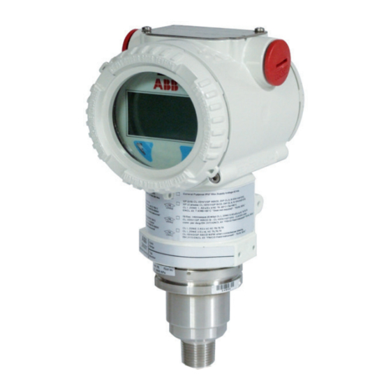
3 Transmitter overview 3 Transmitter overview 3.1 Transmitter components overview Figure 1: Gauge pressure transmitter components 2600T Series Pressure transmitters | OI/266/LowP-EN Rev.A 7... -
Page 8: Range & Span Consideration
3 Transmitter overview 3.2 Range & Span consideration The 2600T Transmitter Specification Sheets provide all information concerning the Range and Span limits in relation to the model and the sensor code. The terminology currently used to define the various parameters is as follows: URL: Upper Range Limit of a specific sensor. -
Page 9: Opening The Box
There is no limit to the storage period, although the terms of guarantee remain as agreed with the Company and as given in the order acknowledgement. AAAAAAAAAAAAAAAAAAAAAAAAAAAAAAAA Model 266HSH Storage temperature limits BBBBBBBBBBBBBBBBBBBBBBBBBBBBBBBB With LCD –40 and 85 °C (–40 and 185 °F) -
Page 10: Mounting
ABB typically configures 266 pressure transmitters technology and safety point of view. according to the user requirements. A typical configuration... -
Page 11: Mounting A P Style Pressure Transmitter
flats of exagon 72 (2.83) Figure 5 Model 266HSH with 1/2-14 NPT male process connection and barrel housing installed on a 2”pipe with optional bracket (B6 carbon steel or B7 Stainless Steel 316L) for sensor P, Q and S 91 (3.58) 18 (0.71) - Page 12 flats 72 (2.83) 108 (4.25) Figure 7: Model 266HSH with 1/2-14 NPT male process connection and barrel housing installed on a 2”pipe with optional bracket (B6 carbon steel or B7 Stainless Steel 316L) for sensor W 91 (3.58) 18 (0.71) 113 (4.45)
-
Page 13: B1 And B2 Barrel Housing Bracket Details
In case of toxic or otherwise dangerous process fluid, take any precautions as recommended in 5 – Fitting adapter (supplied with 266HSH) the relevant Material Safety Data Sheet when draining or venting. Figure 9: Pipe and wall mounting bracket kits for P style Use only a 12 mm (15/32“) hexagonal spanner to tighten the... -
Page 14: Transmitter Wiring
6 Transmitter wiring 6 Transmitter wiring 6.1 Cable connection Warning - General risks. Observe the applicable regulations Depending on the design supplied, the electrical connection is governing electrical installation. Connections must only be established via a cable entry or 1/2-14 NPT thread. The screw established in a dead-voltage state. -
Page 15: Supply Requirement
6 Transmitter wiring 6.3 Supply requirement Warning - General risks. Cable, cable gland and unused port plug For signal connection use, wiring n 18 to 22 AWG / 0.8 to must be in accordance with the intended type of protection (e.g. 0.35mm ø... -
Page 16: Grounding
6 Transmitter wiring 6.5 Grounding Pressure transmitter housing should be grounded or earthed in accordance with national and local electrical codes. Ground connection is mandatory for surge protector equipped devices in order to ensure proper functioning. Protective grounding terminals (PE) are available outside and/or inside the housing of the transmitter. -
Page 17: Commissioning
7 Commissioning 7 Commissioning 7.3 Write Protection Once the transmitter has been installed, it is put into operation by switching on the operating voltage. Write protection prevents the configuration data from being Check the following before switching on the operating voltage: overwritten by unauthorized users. -
Page 18: Operation
8 Operation 8 Operation 8.4 LRV and URV configuration (1 ... 5 V ranging) 8.1 Factory settings — Apply the lower range value for pressure (1 V) from the Transmitters are calibrated at the factory to the customer’s process or from a pressure generator. The pressure must specified measuring range. -
Page 19: Activation Procedure For The Integrated Lcd
8 Operation 8.6 HMI as feedback of the local push button Important. This configuration procedure only changes the 1 … 5V operations signal; it does not affect the physical process pressure (PV value) As consequence of the operations described in the section 8.2, also shown on the digital display or user interface. -
Page 20: Easy Set-Up
8 Operation 8.7.1 Easy Set-up The firtst entry of the Easy Set up menu allows users to select display language. Five selections are possible: English, French, German, Spanish and Italian. Users can select here the engineering unit by pressing ‘Ok’ ‘Next’ key is to be used to move to the next menu item. -
Page 21: Hardware Settings: Dip-Switch Functionality
8 Operation 8.8 Hardware settings: dip-switch functionality 8.9 Damping (DAMPING) There are 4 dip switches located on the electronic module with Pressure transmitter output signals that are noisy as a result of integrated LCD. the process can be smoothed (damped) electrically. Switch 1 and 2 allow the REPLACE MODE for sensor or The additional time constant can be set between 0 s and 60 s secondary electronics. -
Page 22: Custom Linearization Curve
8.11 Configuration with the PC or HHT The 266 transmitters can be configured by either one of the following device. — Hand Held terminals like the ABB DHH805, Emerson Process 375 and 475 provided the 266 EDD has been downloaded and enabled in the terminal. -
Page 23: Error Messages
9 Error messages 9 Error messages 9.1 LCD Display The LCD HMI in case of transmitter errors or malfunctioning is capable of displaying specific error/fault messages to help the user in identifying the problem and resolve it. In case of an alarm, a message consisting of an icon and text appears at the bottom of the process display. - Page 24 9 Error messages The Sensor Temperature Value produced Use a HART configurator (DTM - Hand held) to place Input Simulation C088.030 in output is derived by the value simulated device back in to normal operating mode (Remove no effect Active in input the input simulation) The replacement operation must be executed: Move...
-
Page 25: Maintenance
In case one of the check points above fails, please replace the damaged part with an original spare part. Please contact your local ABB office for spare parts support information or refer to Figure 14: Slot for electronic module removal the spare part list. -
Page 26: Hazardous Area Consideration
11 Hazardous area considerations 11 Hazardous area consideration 11.1 Ex Safety aspects and IP Protection (North America) 11.1.1 Applicable standards According to FM Approvals Standards which can assure compliance with Essential Safety Requirements FM 3600: Electrical Equipment for use in Hazardous (Classified) Locations, General Requirements. FM 3615: Explosionproof Electrical Equipment. -
Page 27: Trouble Sheet
Shipping information for the return of the equipment Material returned for factory repair should be sent to the nearest ABB Service Center; transportation charges prepaid by the Purchaser Please enclose this sheet duty completed to cover letter and packing list... -
Page 28: Return Report
Signed Name Position Date ABB S.p.A Process Automation Division Uffici Commerciali / Sales Office: Via Statale, 113 - 22016 Lenno (CO) Italy Tel. +39 0344 58 111 Fax +39 0344 56 278 e-mail: abb.instrumentation@it.abb.com... - Page 29 Intentionally blank 2600T Series Pressure transmitters | OI/266/LowP-EN Rev.A 29...
- Page 30 Intentionally blank 30 OI/266/LowP-EN Rev.A | 2600T Series Pressure transmitters...
- Page 31 Burlington, Ontario L7N 3W5 – Canada − IEC 61508 SIL2/3 certified temperature sensors and Tel: +1 905 6810565 transmitters Fax: +1 905 6812810 ABB’s portfolio of recorders and controllers: ABB India Limited − Process controllers and indicators Peenya Industrial Area, Peenya − Videographic recorders Bangalore, Karnataka 560058 –...
- Page 32 Howard Road, St. Neots notice. With regard to purchase orders, the agreed Cambridgeshire, PE19 8EU particulars shall prevail. ABB does not accept any responsibility whatsoever for potential errors or possible lack of information in this document. Tel:...
Need help?
Do you have a question about the 266HSH and is the answer not in the manual?
Questions and answers