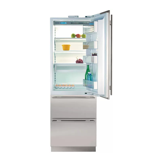
Sub-Zero 700TC-3 Service Manual

Sub-Zero 700TC-3 Service Manual

Integrated 700-3 tall series
Table of Contents

Advertisement

Quick Links

T T e e c c h h n n i i c c a a l l
S S e e r r v v i i c c e e M M a a n n u u a a l l
3 3
3 3
I I n n t t e e g g r r a a t t e e d d
S S e e r r i i e e s s
I I n n t t e e g g r r a a t t e e d d
S S e e r r i i e e s s
( ( 7 7 0 0 0 0 - -
T T A A L L L L ) )
( ( 7 7 0 0 0 0 - -
T T A A L L L L ) )
© SUB-ZERO FREEZER COMPANY INC.
2006 ALL RIGHTS RESERVED
JOB AID #3758412
(Revision B - December 2006)

Advertisement

Table of Contents
loading

Summary of Contents for Sub-Zero 700TC-3

  • Page 1 T T A A L L L L ) ) ( ( 7 7 0 0 0 0 - - T T A A L L L L ) ) © SUB-ZERO FREEZER COMPANY INC. 2006 ALL RIGHTS RESERVED JOB AID #3758412...
  • Page 3: Section 1 - General Information

    Integrated Series Integrated Series General Information (700- ALL) (700- ALL) SECTION 1 GENERAL INFORMATION #3758412 - Revision B - December, 2006...
  • Page 4: Introduction

    Monday through Friday This manual is designed to be used by Authorized Service Personnel only. Sub-Zero Freezer Co., Inc. assumes no responsibility for any repairs made on Sub-Zero refrigeration units by anyone other than Authorized Service Technicians.
  • Page 5: Table Of Contents

    Integrated Series Integrated Series General Information (700- ALL) (700- ALL) TABLE OF CONTENTS Page # Page # Section 1 - General Information Manual Component Activation Mode ......3-25 Temperature Log Recall Mode ........3-26 Introduction ............... 1-2 Compartment Temp. History Only ......3-26 Important Safety Information ..........
  • Page 6 Integrated Series General Information Integrated Series (700- ALL) (700- ALL) Page # Page # Interior Cosmetic, Mechanical and Electrical Section 8 - Troubleshooting Guides Components ..............7-6 to Use Error Code Troubleshooting Guide ....8-2 Door Shelf and Dairy Compartment ......7-6 Error Code Table ............
  • Page 7: Warranty Information

    * Includes, but is not limited to the following: This page summarizes the 2, 5 & 12 Year Residential Electronic Control System Components, Fan & Light Warranty provided with every Sub-Zero, as well as two Switches, Fan Motors & Blades, Defrost & Drain special warranties: Heaters, Defrost Terminator, Drain Pan, Drain Tubes, •...
  • Page 8: Model Description

    Combination 00 Series, ” Wide Refrigerator/Freezer , w/ cemaker, rd Design Build Lower Two Drawer Freezer Zone Figure 1-2. Model 700TC-3 & 700TCI-3 Upper Refrigerator Zone MODEL DESCRIPTION 00 Series, 27” Wide efrigerator, 700TR-3 Design Build Lower Two Drawer Refrigerator Zone Figure 1-3.
  • Page 9 Integrated Series Integrated Series General Information (700- ALL) (700- ALL) MODEL DESCRIPTION Freezer 00 Series, ” Wide rd Design 700TF-3 Build, Variable Speed Compressor Freezer Zone Freezer 700TFI-3 00 Series, ” Wide , w/ cemaker, rd Design Build, Variable Speed Compressor Figure 1-4.
  • Page 10 Integrated Series General Information Integrated Series (700- ALL) (700- ALL) Upper Refrigerator Zone MODEL DESCRIPTION 00 Series, ” Wide efrigerator, 736TR-3 Design Build Lower Two Drawer Refrigerator Zone Figure 1-6. Model 736TR-3 #3758412 - Revision B - December, 2006...
  • Page 11: Section 2 - Installation Information

    Integrated Series Integrated Series Installation Information (700- ALL) (700- ALL) SECTION 2 INSTALLATION INFORMATION #3758412 - Revision B - December, 2006...
  • Page 12: Installation Considerations

    . NOTE: If additional installation information is needed, refer to the complete Installation Manual and/or installation video, or contact the Sub-Zero Technical Assistance Department. UNIT COULD TIP FORWARD UNDER CERTAIN LOAD CONDITIONS. FAILURE TO INSTALL ANTI-TIP COM- PONENTS AND EXTEND LEVELERS TO THE FLOOR ACCORDING TO INSTALLATION MANUAL COULD RESULT IN SERIOUS PERSONAL INJURY OR DEATH.
  • Page 13: Door & Drawer Adjustment

    Integrated Series Integrated Series Installation Information (700- ALL) (700- ALL) The rear levelers are adjusted from the front of the base by turning the Phillips head adjusting screw. The long adjusting screw reaches all the way to the rear lev- eler assembly.
  • Page 14: Dual Unit Installation

    Integrated Series Installation Information Integrated Series (700- ALL) (700- ALL) Dual Unit Installations If two or more units are placed side by side and are 2” or less apart, a dual unit heater package must be applied to the left side of the right hand unit. Apply heater Failure to install the dual unit heater package could to left side of...
  • Page 15: Section 3 - Electronic Control System Information

    Integrated Series Integrated Series Electronic Control System (700- ALL) (700- ALL) SECTION 3 ELECTRONIC CONTROL SYSTEM INFORMATION #3758412 - Revision B - December, 2006...
  • Page 16: Terminology & Component Descriptions

    Integrated Series Electronic Control System Integrated Series (700- ALL) (700- ALL) ELECTRONIC CONTROL TERMINOLOGY & COMPONENT DESCRIPTIONS The electronic control system monitors, regulates and controls a variety of functions. It also displays temperature readings, ice maker system operational status, possible problems with the unit and door ajar alarm status. The table below defines some basic electronic control system terminology and describes some of the electronic control system components.
  • Page 17: Basic Electronic Control System

    Integrated Series Integrated Series Electronic Control System (700- ALL) (700- ALL) BASIC ELECTRONIC CONTROL SYSTEM Input operations for the electronic control system are performed at the control panel (located at the top of the upper compartment), with monitoring, regulating and controlling functions taking place at the control board (located directly behind the control panel).
  • Page 18: Control Board Layout & Summary Table

    Integrated Series Electronic Control System Integrated Series (700- ALL) (700- ALL) CONTROL BOARD LAYOUT AND SUMMARY TABLE The electrical connection points on the control board are labeled alphanumerically. These labels correspond with the alphanumeric control board summary table, located on the wiring diagrams. By referencing the summary table, it is possible to identify which components are connected at which connection points on the control board.
  • Page 19: Control Panel Layout

    Integrated Series Integrated Series Electronic Control System (700- ALL) (700- ALL) CONTROL PANEL LAYOUT Please note that an illustration of the 700TC/I-3 control panel is used in most cases for this section. (See Fig. 3-4) ICEMAKER SYSTEM REFRIGERATOR UNIT ON/OFF KEY SET-POINT ON/OFF (Not present on...
  • Page 20: Adjusting Set-Point (Temp. Adjustment)

    Integrated Series Electronic Control System Integrated Series (700- ALL) (700- ALL) Adjusting Set-Point (Temperature Adjustment) To adjust set-points, press WARMER or COLDER key on control panel in multiple key strokes until desired set-point is achieved (See Figure 3-6). One key stroke equals one degree change. NOTE: The temperature range in a freezer zone is -5°F (-21°C) to +5°F (-15°C).
  • Page 21: Unique Electronic Control Input Operations

    Integrated Series Integrated Series Electronic Control System (700- ALL) (700- ALL) UNIQUE ELECTRONIC CONTROL INPUT OPERATIONS The following pages illustrate unique input operations performed at the control panel that you would not expect a customer to perform every day. The input operations described are: Temperature Unit Selection Mode, Sabbath Mode, Showroom Mode, Manual Zone Disable Mode and Manual Freezer Evaporator Defrost.
  • Page 22: Sabbath Mode

    Integrated Series Electronic Control System Integrated Series (700- ALL) (700- ALL) Sabbath Mode Sabbath Mode was incorporated into the electronic control system for the observance of certain religious days. Initiating Sabbath Mode disables the LCD, lighting system, ice making system and door ajar alarm feature. To initiate Sabbath Mode, the unit must first be switched OFF using the UNIT ON/OFF key (See Figure 3-11), then press and hold the UNIT ON/OFF key until the LCD and lights switch OFF, approximately ten (10) seconds (See Figure 3-12).
  • Page 23: Manual Zone Disable Mode

    Integrated Series Integrated Series Electronic Control System (700- ALL) (700- ALL) Manual Zone Disable Mode Manual Zone Disable Mode allows a customer or Service Technician to switch one zone off for interior cleaning, defrosting, or diagnostic purposes, while allowing the other zone to continue cooling. To initiate Manual Zone Disable Mode, the unit must first be switched OFF using the UNIT ON/OFF key (See Figure 3-15), then press and hold the WARMER key for the zone being disabled, then the UNIT ON/OFF key, then release both keys (See Figure 3-16).
  • Page 24: Functions Of The Electronic Control System

    Integrated Series Electronic Control System Integrated Series (700- ALL) (700- ALL) FUNCTIONS OF THE ELECTRONIC CONTROL SYSTEM The following pages explain monitoring, regulating and controlling functions of the electronic control system. In most cases signal traces of a model 700TCI-3 wiring schematic are used to show current flow for functions being explained.
  • Page 25 Integrated Series Integrated Series Electronic Control System (700- ALL) (700- ALL) Monitor, Regulate and Display Compartment Temperatures The temperature signal from the compartment thermistor is monitored by the microprocessor and then displayed on the LCD. Though the compartment air temperature does fluctuate, the LCD displays the average temperature (See Figure 3-19).
  • Page 26 Integrated Series Electronic Control System Integrated Series (700- ALL) (700- ALL) Assist in Control of Variable Speed Compressors (700TF/I-3 Only) As mentioned on the previous page, temperature signals from the thermistors in the compartment are monitored by the microprocessor and then displayed on the LCD. When the compartment reaches high-offset (calling for cooling), an “ON”...
  • Page 27: Control Condenser Fan Run

    Integrated Series Integrated Series Electronic Control System (700- ALL) (700- ALL) Control Condenser Fan Run In all models except the 700TF/I-3, the microprocessor senses the 115 volt output supplied to both compressors. If either compressor is running, a signal is sent to the condenser fan relay on the control board to close, supplying power to the condenser fan.
  • Page 28: Refrigerator "Fan-Assisted Off-Cycle Defrost

    Integrated Series Electronic Control System Integrated Series (700- ALL) (700- ALL) Monitor and Control Refrigerator “Fan-Assisted, Off-Cycle Defrost” Temperature signals from refrigerator evaporator's thermistor’s are observed by the microprocessor. During off cycle defrost, if a refrigerator zone temperature reaches high offset (calling for cooling) before evaporator temperature rises to 38°F (3°C), no power will be supplied the the compressor.
  • Page 29: Freezer "Adaptive Defrost

    Integrated Series Integrated Series Electronic Control System (700- ALL) (700- ALL) Monitor and Control Freezer “Adaptive Defrost” Initially the freezer compressor will cycle-run for twelve hours (twenty-four hours in the model 700TF/I-3), after which the microprocessor sends the signal to the defrost relay on the control board to close. This supplies power to the defrost heater, and the compressor is switched off (See Figure 3-24).
  • Page 30 Integrated Series Electronic Control System Integrated Series (700- ALL) (700- ALL) Monitor Compressor Run Duration, Displays If Service is Needed In all models except the 700TF/I-3, the microprocessor observes the changing state of the compressor relays to determine the length of compressor run time (See Figure 3-25). If a compressor runs 100% (Fre = 6 hours / Ref = 4 hours), an error code is logged (EC 40 / EC 50, respectively), and defrost is initiated, but SERVICE will not flash.
  • Page 31 Integrated Series Integrated Series Electronic Control System (700- ALL) (700- ALL) Monitor Icemaker System and Display If Service is Needed The microprocessor observes the 115 Volts AC supplied to the icemaker water valve solenoid. If the solenoid is energized for more than 15 seconds, power to the icemaker system is disabled for 24 hours (See Figure 3-28), and an error code is logged (EC 30).
  • Page 32: Possible Error Indicators

    Integrated Series Electronic Control System Integrated Series (700- ALL) (700- ALL) POSSIBLE ERROR INDICATORS These pages contain diagrams illustrating what a customer may see on the LCD if there is a problem with the unit. NOTE: To clear indicators and error codes, problem must be corrected then press Bell ON/OFF key for 15 seconds. NOTE: For thermistor errors described below, thermistor can be tested by submersing it in a glass of ice water for 2 to 5 minutes, then check for 30,000 to 33,000 ohms.
  • Page 33: 700Tr-3 & 736Tr-3

    Integrated Series Integrated Series Electronic Control System (700- ALL) (700- ALL) SERVICE UNIT FREEZER REFRIGERATOR COLDER WARMER COLDER WARMER ON/OFF ON/OFF ON/OFF Figure 3-37. 700TR-3 & 736TR-3 “EE” at Left and “SERVICE” Flashing = Lower Compartment Thermistor (or its Wiring) Fault SERVICE UNIT FREEZER...
  • Page 34 Integrated Series Electronic Control System Integrated Series (700- ALL) (700- ALL) SERVICE UNIT FREEZER REFRIGERATOR COLDER WARMER COLDER WARMER ON/OFF ON/OFF ON/OFF Figure 3-43. 700TF/I-3 “EE” at Left and “SERVICE” Flashing = Freezer Compartment Thermistor (or its Wiring) Fault SERVICE UNIT FREEZER REFRIGERATOR...
  • Page 35: Troubleshooting Input Operations

    Integrated Series Integrated Series Electronic Control System (700- ALL) (700- ALL) TROUBLESHOOTING INPUT OPERATIONS The following few pages explain troubleshooting input operations performed at the control panel. The input opera- tions described are Diagnostic Mode, Manual Component Activation Mode and Temperature Log Recall. Diagnostic Mode Initiating Diagnostic Mode allows the Service Technician to observe real-time temperature readings from all thermis- tors without temperature averaging.
  • Page 36: Diagnostic Mode Indicators

    Integrated Series Electronic Control System Integrated Series (700- ALL) (700- ALL) 700TC/I-3 & 736TC/I-3 700TR-3 & 736TR-3 700TF/I-3 THERMISTOR LOCATION CODE THERMISTOR LOCATION CODE THERMISTOR LOCATION CODE Freezer Compartment Lower Compartment Freezer Compartment Refrigerator Compartment Upper Compartment Freezer Evaporator Freezer Evaporator Lower Evaporator Refrigerator Evaporator Upper Evaporator...
  • Page 37: Error Code Table

    Integrated Series Integrated Series Electronic Control System (700- ALL) (700- ALL) Error Code Table CODE INDICATION Refrig. cabinet thermistor read open or shorted for 10+ seconds, or repeatedly read erratic temp’s Refrig. evaporator thermistor read open or shorted for 10+ seconds, or repeatedly read erratic temp’s Freezer cabinet thermistor read open or shorted for 10+ seconds, or repeatedly read erratic temp’s Freezer evaporator thermistor read open or shorted for 10+ seconds, or repeatedly read erratic temp’s Defrost under-heat with no voltage feedback through Gray/White wire at defrost start...
  • Page 38: Manual Component Activation Mode

    Integrated Series Electronic Control System Integrated Series (700- ALL) (700- ALL) Manual Component Activation Mode Manual Component Activation Mode allows a Service Technician to energize a cooling system for five minutes. When activated, the chosen zone’s compressor and evaporator fan are energized along with the condenser fan. While in Component Activation Mode, the evaporator temperatures for that zone are displayed on the LCD.
  • Page 39: Temperature Log Recall Mode

    Integrated Series Integrated Series Electronic Control System (700- ALL) (700- ALL) Temperature Log Recall Mode The electronic control system is equipped with a temperature history data storage system. This system logs/stores the average temperature of each individual thermistor every two hours, along with any event indicators (explained later in this section), that may have occurred.
  • Page 40 Integrated Series Electronic Control System Integrated Series (700- ALL) (700- ALL) Initiate Temperature Log Recall Mode To View Compartment and Evaporator Temperature History - Begin with the unit ON and in Diagnostic Mode (See Figure 3-63). While in Diagnostic Mode, toggle through the readings until the desired thermistor temperature is displayed on the LCD (See Figure 3-64).
  • Page 41: Possible Event Indicators

    Integrated Series Integrated Series Electronic Control System (700- ALL) (700- ALL) Possible Temperature Log Recall Mode Event Indicators The diagrams below illustrate possible event indicators that may be observed while in Temperature Log Recall Mode. (See Figures 3-69 through 3-72) UNIT FREEZER COLDER...
  • Page 42: Temperature Log Index Chart

    Integrated Series Electronic Control System Integrated Series (700- ALL) (700- ALL) Temperature Log Index Chart NOTE : The chart below applies to the hours in which the control has power. Temperature history data will only be stored when the control has 115V AC supplied to it. If power to the unit is interrupted, the average temperatures for that time period are stored with the event indicator.
  • Page 43: Section 4 - Sealed System Information

    Integrated Series Integrated Series Sealed System Information (700- ALL) (700- ALL) SECTION 4 SEALED SYSTEM INFORMATION #3758412 - Revision B - December, 2006...
  • Page 44: Hfc-134A Refrigerant Service Information

    Integrated Series Sealed System Information Integrated Series (700- ALL) (700- ALL) HFC-134a REFRIGERANT SERVICE INFORMATION The 700-3 Series sealed systems contain HFC-134a refrigerant. This section provides some general rules for work- ing with 134a, and explains procedures to be followed while servicing the sealed system. This is followed by dia- grams which illustrate sealed system operation, then model-specific refrigerant flow diagrams.
  • Page 45: Sealed System Repair Procedures

    Integrated Series Integrated Series Sealed System Information (700- ALL) (700- ALL) SEALED SYSTEM REPAIR PROCEDURES Problem Service Procedures Non-Operating, Inefficient, Capture refrigerant Noisy Compressor Replace Compressor Replace filter-drier Evacuate or sweep charge system Recharge system with Virgin 134a refrigerant. NOTE: To check for a non-operating compressor, a hard start kit can be used. High Side leak Capture refrigerant.
  • Page 46: Sealed System Operation

    Integrated Series Sealed System Information Integrated Series (700- ALL) (700- ALL) SEALED SYSTEM OPERATION The six diagrams on these pages illustrate a basic sealed system. The components are listed in order of refrigerant flow, with an explanation of their fundamental role as part of a sealed system.
  • Page 47 Integrated Series Integrated Series Sealed System Information (700- ALL) (700- ALL) Capillary Tube (& Heat Exchanger) (Figure 4-4) The warm liquid refrigerant travels through the long skinny capillary tube which is soldered to the suction line. (These two tubes soldered together create the heat exchanger.) As the warm liquid refrigerant travels through the capillary tube it gives up heat to the cool refrigerant gas traveling through the suction line and the pressure drops, so it is a...
  • Page 48: Sealed System Refrigerant Flow Diagrams

    Integrated Series Sealed System Information Integrated Series (700- ALL) (700- ALL) SEALED SYSTEM REFRIGERANT FLOW DIAGRAMS = REFRIGERATOR SEALED SYSTEM = FREEZER SEALED SYSTEM FRAME HEATER (HOT GAS) REFRIGERATOR EVAPORATOR REFRIGERATOR HEAT-EXCHANGER FREEZER HEAT-EXCHANGER FREEZER EVAPORATOR FREEZER FILTER-DRIER REFRIGERATOR COMPRESSOR REFRIGERATOR FILTER-DRIER CONDENSER (FRONT - FREEZER)
  • Page 49: Model 700Tf/I-3

    Integrated Series Integrated Series Sealed System Information (700- ALL) (700- ALL) = UPPER REFRIGERATOR SEALED SYSTEM = LOWER REFRIGERATOR SEALED SYSTEM FRAME HEATER (HOT GAS) REFRIGERATOR EVAPORATOR (UPPER) REFRIGERATOR HEAT-EXCHANGER (UPPER) REFRIGRATOR HEAT-EXCHANGER REFRIGERATOR EVAPORATOR (LOWER) (LOWER) REFRIGERATOR FILTER-DRIER (UPR) REFRIGERATOR COMPRESSOR REFRIGERATOR FILTER-DRIER (LWR) (UPPER)
  • Page 50 Integrated Series Sealed System Information Integrated Series (700- ALL) (700- ALL) #3758412 - Revision B - December, 2006...
  • Page 51: Section 5 - Air Flow & Fan Blade Spacing

    Integrated Series Integrated Series Airflow & Fan Blade Spacing (700- ALL) (700- ALL) SECTION 5 AIR FLOW & FAN BLADE SPACING #3758412 - Revision B - December, 2006...
  • Page 52 Integrated Series Airflow & Fan Blade Spacing Integrated Series (700- ALL) (700- ALL) UPPER FAN MOTOR Bracket Clamp Blade Away From Motor 700TC/I-3: 1” ± 3/32” (25.4 mm ± 0.8 mm) 736TC/I-3: 7/8” ± 1/16” LOWER FAN MOTOR (22.2 mm ± 1.6 mm) Clamp Bracket Away From...
  • Page 53 Integrated Series Integrated Series Airflow & Fan Blade Spacing (700- ALL) (700- ALL) UPPER FAN MOTOR Bracket Clamp Blade Away From Motor 700TR-3: 1” ± 3/32” (25.4 mm ± 0.8 mm) 736TR-3: 7/8” ± 1/16” LOWER FAN MOTOR (22.2 mm ± 1.6 mm) Bracket Clamp Blade...
  • Page 54 Integrated Series Airflow & Fan Blade Spacing Integrated Series (700- ALL) (700- ALL) #3758412 - Revision B - December, 2006...
  • Page 55: Section 6 - Icemaker Information

    Integrated Series Integrated Series Icemaker Information (700- ALL) (700- ALL) SECTION 6 ICEMAKER INFORMATION #3758412 - Revision B - December, 2006...
  • Page 56: Modular Icemaker

    Integrated Series Icemaker Information Integrated Series (700- ALL) (700- ALL) ICEMAKER SYSTEM INFORMATION The model 700TFI-3 utilizes a Modular ® icemaker, while the models 700TCI-3 and 736TCI-3 utilize either a MidSouth ® Icemaker, or Japan-Servo ® Icemaker. This section is divided in two parts ICEMAKER MODEL PAGES Modular Icemaker Information (Model 700TFI-3 Only) ................
  • Page 57: Modular Icemaker Operation

    Integrated Series Integrated Series Icemaker Information (700- ALL) (700- ALL) MODULAR ICEMAKER OPERATION (700TFI-3 ONLY) When the icemaker thermostat has sensed temperatures of 17°F, the thermostat closes. At this time, the current now has a path through the thermostat to the motor. The motor is linked with the drive gear. From the module, there are copper contacts that ride on copper strips on the backside of the drive gear.
  • Page 58: Modular Icemaker Test Procedures

    Integrated Series Icemaker Information Integrated Series (700- ALL) (700- ALL) MODULAR ICEMAKER TEST PROCEDURES (700TFI-3 ONLY) Perform the following tests if the icemaker is thought to be defective. See Figure 6-3 for icemaker test port loca- tions. Test 1 through 5 are performed with AC power supplied to the icemaker, so read the “WARNING” below and the “additional Ice Production Notes”...
  • Page 59: Water Fill Adjustment

    Integrated Series Integrated Series Icemaker Information (700- ALL) (700- ALL) MODULAR ICEMAKER WATER FILL ADJUSTMENT (700TFI-3 ONLY) The water valve should energize for approximately 7.5 seconds. This should supply 140cc. of water to the ice- maker, or approximately 4.75oz. If this is not the case, the fill amount can be adjusted with the water fill adjust- ment screw.
  • Page 60 Integrated Series Icemaker Information Integrated Series (700- ALL) (700- ALL) MIDSOUTH AND JAPAN-SERVO ICEMAK- Bearing / Inlet - The bearing / inlet is attached to the ice mold, opposite the support. Water enters the bear- ER COMPONENTS ing / inlet and is directed to the ice mold. The (700TCI-3 AND 736TCI-3 ONLY) bearing/inlet also supports the ice ejector at the end opposite the timing cam.
  • Page 61 Integrated Series Integrated Series Icemaker Information (700- ALL) (700- ALL) 115 VOLTS 60 CYCLES THERMOSTAT SHUT-OFF SWITCH MOLD HEATER MIDSOUTH AND JAPAN-SERVO ICEMAKER OPERATION (700TCI-3 AND 736TCI-3 ONLY) SOLENOID SWITCH The following series of electrical schematics illustrate a typical icemaker cycle of operation. Below each MOTOR schematic is a diagram indicating the approximate loca- WATER...
  • Page 62 Integrated Series Icemaker Information Integrated Series (700- ALL) (700- ALL) 115 VOLTS 60 CYCLES THERMOSTAT SHUT-OFF SWITCH MOLD HEATER SOLENOID SWITCH First Revolution Continued (See Figure 6-10) MOTOR • The holding switch is tripped by the timing cam to WATER “normally open”...
  • Page 63 Integrated Series Integrated Series Icemaker Information (700- ALL) (700- ALL) 115 VOLTS 60 CYCLES THERMOSTAT SHUT-OFF SWITCH MOLD HEATER First Revolution Continued (See Figure 6-12) • The ice has released from the mold. SOLENOID SWITCH • The motor remains energized through the holding switch.
  • Page 64 Integrated Series Icemaker Information Integrated Series (700- ALL) (700- ALL) 115 VOLTS 60 CYCLES THERMOSTAT SHUT-OFF SWITCH MOLD HEATER Start of Second Revolution (See Figure 6-14) SOLENOID SWITCH • The water valve solenoid switch is tripped by the timing cam back to “normally open.” MOTOR WATER •...
  • Page 65 Integrated Series Integrated Series Icemaker Information (700- ALL) (700- ALL) 115 VOLTS 60 CYCLES THERMOSTAT SHUT-OFF SWITCH MOLD HEATER Second Revolution Continued (See Figure 6-16) SOLENOID SWITCH • The water valve solenoid switch is tripped by the MOTOR timing cam. This time the solenoid is energized WATER because the thermostat is open.
  • Page 66 Integrated Series Icemaker Information Integrated Series (700- ALL) (700- ALL) MANUALLY STOPPING ICE PRODUCTION Ice production can be manually stopped three ways: 1. Press the ICE ON/OFF key on the control panel so that “ICE” is not displayed on the LCD. 2.
  • Page 67 Integrated Series Integrated Series Icemaker Information (700- ALL) (700- ALL) ICEMAKER FAULT TESTING Possible Problems No / Slow Ice Production Bypass 45-minute dwell by pressing ICE ON/OFF key to OFF 1 Ice maker system switched OFF. Switch ice system ON. then ON.
  • Page 68 Integrated Series Icemaker Information Integrated Series (700- ALL) (700- ALL) 6-14 #3758412 - Revision B - December, 2006...
  • Page 69: Section 7 - Component Access And Removal

    Integrated Series Integrated Series Component Access/Removal (700- ALL) (700- ALL) SECTION 7 COMPONENT ACCESS AND REMOVAL #3758412 - Revision B - December, 2006...
  • Page 70: Component Access And Removal

    Integrated Series Component Access/Removal Integrated Series (700- ALL) (700- ALL) COMPONENT ACCESS AND REMOVAL This section explains how to adjust, access and remove components in and from 700-3 Tall Series units. If different models have similar adjusting, accessing and/or removal procedures, they are grouped together under the appropriate heading.
  • Page 71: Exterior Cosmetic And Mechanical Components

    Integrated Series Integrated Series Component Access/Removal (700- ALL) (700- ALL) EXTERIOR COSMETIC AND MECHANICAL COMPONENTS Kickplate/Grille Removal (All Models) The kickplate/grille is attached by four screws passing through the kickplate into adjustable kickplate brackets. NOTE: Because drawer panels may extend down in front of the kickplate/grille, it may be necessary to remove the bottom drawer to gain access.
  • Page 72: Drawer Assembly

    Integrated Series Component Access/Removal Integrated Series (700- ALL) (700- ALL) Drawer Assembly Removal (All Models) There are inverted channels on both sides of the draw- er tubs which rest on telescoping drawer slide assem- Hole in Channel blies. A pin at the front of each drawer slide fits into a hole in the inverted channel of each drawer tub, holding the drawer assembly in place.
  • Page 73: Door Assembly

    Integrated Series Integrated Series Component Access/Removal (700- ALL) (700- ALL) Door Assembly Removal (All Models) Remove two inner-most screws at top and bottom The door assembly is held in place with Allen-head hinge with door open. Remove two outer-most screws that pass down through the arm of the top hinge screws at bottom hinge assembly and up through the arm of the bottom hinge first then at top, with door...
  • Page 74: Interior Cosmetic, Mechanical And Electrical Components

    Integrated Series Component Access/Removal Integrated Series (700- ALL) (700- ALL) INTERIOR COSMETIC, MECHANICAL AND ELEC- TRICAL COMPONENTS Door Shelf Door Shelf and Dairy Compartment Adjustment / Removal (All Models) There are “L” shaped grooves in the end caps of the “L”...
  • Page 75: Upper Light Diffuser

    Integrated Series Integrated Series Component Access/Removal (700- ALL) (700- ALL) Upper Light Diffuser Removal (All Models) “T” Slots The side frames of the upper light diffuser have four inverted “T” shaped slots (two each side) which fit over pegs protruding from the side walls of the upper com- partment.
  • Page 76: Control Board

    Integrated Series Component Access/Removal Integrated Series (700- ALL) (700- ALL) Control Board Removal (All Models) The control board is held in position by two sets of tabs behind the left side of the control panel. The two for- ward tabs position the LCD in the control panel window, Control Panel while the other two tabs secure the middle of the control board.
  • Page 77: Upper Evaporator Cover / Air Duct

    Integrated Series Integrated Series Component Access/Removal (700- ALL) (700- ALL) Upper Evaporator Cover / Air Duct Removal (All Models) The bottom of the upper evaporator cover sets into a channel at the bottom of the upper compartment. At the top, screws hold the evaporator cover to the evapo- rator fan shroud.
  • Page 78: Upper Compartment Thermistor

    Integrated Series Component Access/Removal Integrated Series (700- ALL) (700- ALL) Upper Compartment Evaporator Fan Assembly Removal (All Models) The upper evaporator fan assembly sets in a pocket in the ceiling of the upper compartment and is secured to the ceiling with screws. To access and remove the evaporator fan assembly, first remove light diffuser, evaporator cover, and evapo- rator fan shroud assembly, then (See Figure 7-18):...
  • Page 79: Drawer Closer Assembly

    Integrated Series Integrated Series Component Access/Removal (700- ALL) (700- ALL) Drawer Closer Assembly Removal (All Models) Drawer Closer Assy The drawer closer assemblies are located on the right side wall, towards the front of the two drawer areas. Screws secure each drawer closer to the wall. To access and remove a drawer closer assembly, first remove the appropriate drawer.
  • Page 80: Heat Exchanger Cover

    Integrated Series Component Access/Removal Integrated Series (700- ALL) (700- ALL) Heat Exchanger Cover Removal (All Models) The heat exchanger cover is held in the back left corner of the lower compartment with screws that go through the cover and into stand-offs. (See Figure 7-24) Screw To access and remove the heat exchanger cover, the drawers and the left side drawer slides will need to be...
  • Page 81 Integrated Series Integrated Series Component Access/Removal (700- ALL) (700- ALL) Lower Compartment Thermistor Removal (Models 700TR-3 & 736TR-3) The lower compartment thermistor in these models is attached at front of the switch enclosure with a screw. Switch Enclosure To access and remove the lower compartment thermis- tor, first remove drawers, left side drawer slides, heat exchanger cover and lower evaporator cover, then (See Figure 7-27):...
  • Page 82: (700Tc/I-3, 700Tf/I-3, 736Tc/I-3)

    Integrated Series Component Access/Removal Integrated Series (700- ALL) (700- ALL) Drain Trough Heater Removal (Models 700TC/I-3, 700TF/I-3, 736TC/I-3) The drain trough heater in the lower compartment is positioned just above the drain trough and held in place by three heater brackets. Heater Brackets To access and remove the drain trough heater, first remove drawers, left side drawer slides, heat exchanger...
  • Page 83: Defrost Terminator (700Tc/I-3, 700Tf/I-3, 736Tc/I-3)

    Integrated Series Integrated Series Component Access/Removal (700- ALL) (700- ALL) Defrost Terminator Removal (700TC/I-3, 700TF/I-3 & 736TC/I-3) Remove these screws The defrost terminator is attached to the second tubing and pull evap forward slightly pass from the top of the evaporator. To access and remove the defrost terminator, first remove drawers, left side drawer slides, heat exchanger cover, evaporator cover and the evaporator fan shroud,...
  • Page 84: Switch Enclosure Assembly

    Integrated Series Component Access/Removal Integrated Series (700- ALL) (700- ALL) Switch Enclosure Assembly Removal (All Models) Lower switch enclosure assemblies are held at the back right corner of the compartment with screws at the top and bottom left corners, and depending on the model, Disconnect electrical leads one or two along the right side.
  • Page 85: Lower Compartment Thermistor

    Integrated Series Integrated Series Component Access/Removal (700- ALL) (700- ALL) Lower Compartment Thermistor Removal Thermistor (700TC/I-3, 700TF/I-3 & 736TC/I-3) The lower compartment thermistor in these models is attached to the back wall with a screw. To access and remove the lower compartment thermis- tor, first remove drawers, left side drawer slides, heat exchanger cover, lower evaporator cover and the switch enclosure, then (See Figure 7-36):...
  • Page 86: Compressor Area Electrical & Mechanical Components

    Integrated Series Component Access/Removal Integrated Series (700- ALL) (700- ALL) COMPRESSOR AREA ELECTRICAL AND MECHANI- CAL COMPONENTS Screw Icemaker Water Valve Removal (700TC/I-3, 700TF/I-3 & 736TC/I-3) The icemaker water valve assembly is located at the right side of the compressor area next to the condenser, and is attached to the valve bracket with screws.
  • Page 87: Condenser Fan Assembly

    Integrated Series Integrated Series Component Access/Removal (700- ALL) (700- ALL) Condenser Fan Assembly Removal Screw The condenser fan shroud sets on top of two pegs pro- truding from the unit tray and two screws at the top of the shroud secure it to the condenser. The condenser fan is mounted to the condenser fan shroud.
  • Page 88: Sealed System Components

    Integrated Series Component Access/Removal Integrated Series (700- ALL) (700- ALL) SEALED SYSTEM COMPONENTS Upper Refrigerator Compartment Evaporator Removal (All Models except 700TF/I-3) 1" The upper evaporator is attached to the back wall with screws. NOTE: Before attempting to remove the evaporator, 2"...
  • Page 89: High-Side Filter-Drier

    Integrated Series Integrated Series Component Access/Removal (700- ALL) (700- ALL) High-Side Filter-Drier Removal Screw The high-side filter-driers are located in the center of the unit tray, behind the condenser and are attached to the drier bracket with a cable tie. NOTE: Before attempting to remove a filter drier, evac- uate the refrigerant from the sealed system.
  • Page 90: Compressor

    Integrated Series Component Access/Removal Integrated Series (700- ALL) (700- ALL) Compressor Removal The compressors have four rubber compressor grom- mets inserted into their base. Cylindrical metal spacers are placed over threaded studs that are pressed into the unit tray. The compressor grommets fit over the spacers and a washer sets on top of the grommet and spacer.
  • Page 91: Condenser

    Integrated Series Integrated Series Component Access/Removal (700- ALL) (700- ALL) Condenser Removal Screw The condenser is secured to the unit tray by four rivets that pass up through the unit tray into the condenser side brackets. NOTE: Before attempting to remove the condenser, evacuate the refrigerant from the sealed system(s).
  • Page 92: Upper Compartment Heat Exchanger

    Integrated Series Component Access/Removal Integrated Series (700- ALL) (700- ALL) Upper Compartment Heat Exchanger Removal 1" The upper compartment heat exchanger passes down through a hole in the back left corner of the mullion. The heat exchanger then passes down through the 2"...
  • Page 93: Lower Compartment Heat Exchanger

    Integrated Series Integrated Series Component Access/Removal (700- ALL) (700- ALL) Lower Compartment Heat Exchanger Removal The lower compartment heat exchanger is behind the switch enclosure and passes down through a hole in the back right corner of the lower compartment floor. 1"...
  • Page 94 Integrated Series Component Access/Removal Integrated Series (700- ALL) (700- ALL) 7-26 #3758412 - Revision B - December, 2006...
  • Page 95: Section 8 - Troubleshooting Guides

    Integrated Series Integrated Series Troubleshooting Guides (700- ALL) (700- ALL) SECTION 8 TROUBLESHOOTING GUIDES #3758412 - Revision B - December, 2006...
  • Page 96: How To Use Error Code Troubleshooting Guide

    Integrated Series Troubleshooting Guides Integrated Series (700- ALL) (700- ALL) TROUBLESHOOTING GUIDES This section of the manual contains: • The Error Code Table and Error Code Troubleshooting Guide. • The General Troubleshooting Guide, which covers all problems that a 700-3 Series unit may experience. •...
  • Page 97: Error Code Troubleshooting Guide

    Integrated Series Integrated Series Troubleshooting Guides (700- ALL) (700- ALL) ERROR CODE TROUBLESHOOTING GUIDE ERROR CODE TEST / ACTION Check refrigerator compartment thermistor electrical connections and continuity from thermistor to J1 on control board. Reconnect / repair connections. Check resistance of refrigerator compartment thermistor for 30,000 to 33,000 ohms at 32°F (0°C). Replace if defective.
  • Page 98 Integrated Series Troubleshooting Guides Integrated Series (700- ALL) (700- ALL) ERROR CODE TROUBLESHOOTING GUIDE ERROR CODE TEST / ACTION A. Check for jammed cube in icemaker. B. Reference wiring diagram to identify components in same White wire circuit as water valve solenoid. Check all White wire electrical connections and continuity from water valve solenoid to J7-8 on control board.
  • Page 99: How To Use The General Troubleshooting Guide

    Integrated Series Integrated Series Troubleshooting Guides (700- ALL) (700- ALL) HOW TO USE GENERAL TROUBLESHOOTING GUIDE The General Troubleshooting Guide Table of Contents on the following page indicates how the General Trouble Shooting Guide is arranged. Match the description of the problem the unit is experiencing with those in the table. To the left of the problem description is a letter.
  • Page 100: General Troubleshooting Guide Table Of Contents

    Integrated Series Troubleshooting Guides Integrated Series (700- ALL) (700- ALL) GENERAL TROUBLESHOOTING GUIDE TABLE OF CONTENTS Ltr Problem Description Page # Error Codes and “SERVICE” Flashing ..........................8-7 “EE” Displayed in Place of Freezer Temperature with “SERVICE” Flashing ............... 8-7 C.
  • Page 101: Ee" Displayed In Place Of Freezer Temperature With "Service" Flashing

    Integrated Series Integrated Series Troubleshooting Guides (700- ALL) (700- ALL) PROBLEM POSSIBLE CAUSE TEST / ACTION A. Error Codes & “SERVICE” Unit Experienced Temperature Problems See Error Code Troubleshooting Guide Flashing B. “EE” Displayed in Place of Freezer Compartment Thermistor Check wiring from thermistor to control Freezer Temperature with Disconnected, Shorted, or Misread...
  • Page 102 Integrated Series Troubleshooting Guides Integrated Series (700- ALL) (700- ALL) PROBLEM POSSIBLE CAUSE TEST / ACTION (Continued) Light ON with Door/ Drawers Closed G. Warm Freezer Temperature a. Top hinge cover missing, not depress- a. Replace hinge cover. with “SERVICE” Flashing ing light switch b.
  • Page 103 Integrated Series Integrated Series Troubleshooting Guides (700- ALL) (700- ALL) PROBLEM POSSIBLE CAUSE TEST / ACTION H. Warm Freezer Temperatures No Power to Unit Check power to unit, plug unit in or switch without “SERVICE” Flashing supply circuit breaker ON. Pointers: Unit Switched OFF Check for “OFF”...
  • Page 104 Integrated Series Troubleshooting Guides Integrated Series (700- ALL) (700- ALL) PROBLEM POSSIBLE CAUSE TEST / ACTION (Continued) Evaporator Fan Fault H. Warm Freezer Temperatures a. Top hinge cover missing, not depress- a. Replace hinge cover. without “SERVICE” Flashing ing fan switch b.
  • Page 105 Integrated Series Integrated Series Troubleshooting Guides (700- ALL) (700- ALL) PROBLEM POSSIBLE CAUSE TEST / ACTION I. Warm Refrigerator Door or Drawer Ajar Temperatures with “SERVICE” Flashing a. Food product obstruction a. Move obstruction. b. Door/cabinet hinge problem b. See Door Hinge Operation Test Procedures Pointers: later in this section.
  • Page 106 Integrated Series Troubleshooting Guides Integrated Series (700- ALL) (700- ALL) PROBLEM POSSIBLE CAUSE TEST / ACTION (Continued) Evaporator Heavily Frosted I. Warm Refrigerator a. Door or drawer ajar a. See Door or Drawer Ajar above. Temperatures with b. Evaporator fan fault b.
  • Page 107 Integrated Series Integrated Series Troubleshooting Guides (700- ALL) (700- ALL) PROBLEM POSSIBLE CAUSE TEST / ACTION (Continued) Lights ON with Door/ Drawers Closed J. Warm Refrigerator a. Top hinge cover missing, not depress- a. Replace hinge cover. Temperatures without ing light switch “SERVICE”...
  • Page 108 Integrated Series Troubleshooting Guides Integrated Series (700- ALL) (700- ALL) PROBLEM POSSIBLE CAUSE TEST / ACTION K. Warm or Normal High Room Ambient Instruct customer unit performs best Temperatures in Both between 60°F(16°C) and 90°F(32°C). Compartments with “SERVICE” Flashing Condenser Air Flow a.
  • Page 109 Integrated Series Integrated Series Troubleshooting Guides (700- ALL) (700- ALL) PROBLEM POSSIBLE CAUSE TEST / ACTION (Continued) Condenser Air Flow L. Warm Temperatures in Both Compartments without a. Dirty condenser a. Clean condenser. “SERVICE” Flashing b. Condenser fan blade obstructed or b.
  • Page 110: No Ice, "Ice" Displayed On Lcd, But Not Flashing

    Integrated Series Troubleshooting Guides Integrated Series (700- ALL) (700- ALL) PROBLEM POSSIBLE CAUSE TEST / ACTION P. No Ice, "ICE" Displayed on Unit Has Not Run Long Enough Freezer must be 17°F for icemaker to oper- LCD, but not Flashing ate, approximately 24 hours after unit instal- lation.
  • Page 111: Icemaker Produces Hollow Cubes

    Integrated Series Integrated Series Troubleshooting Guides (700- ALL) (700- ALL) PROBLEM POSSIBLE CAUSE TEST / ACTION Q. No Ice and "ICE" Not Icemaker System Not Energized Press ICE key. “ ICE” should appear on Displayed on LCD LCD. R. Icemaker produces Too Ice Level Arm/Linkage Bent or Broken Inspect ice level arm, shut-off arm and link- much ice...
  • Page 112: Membrane Switch On Control Board Malfunctioning

    Integrated Series Troubleshooting Guides Integrated Series (700- ALL) (700- ALL) PROBLEM POSSIBLE CAUSE TEST / ACTION V. Membrane Switch on Control Control Panel Ribbon Cable Check control panel ribbon cable. All Pins Board Malfunctioning Disconnected or Connected Incorrectly on board should be in ribbon cable terminal housing.
  • Page 113: Door Or Drawers Not Able To Close Completely

    Integrated Series Integrated Series Troubleshooting Guides (700- ALL) (700- ALL) PROBLEM POSSIBLE CAUSE TEST / ACTION X. Lights Stay ON when Door Door or Drawer Ajar &/or Drawers are Closed - (May be Accompanied by a. Food product obstruction a. Move obstruction. Door/Drawer Ajar Alarm Bell) b.
  • Page 114: Sealed System Troubleshooting / Diagnostic Tables

    Integrated Series Troubleshooting Guides Integrated Series (700- ALL) (700- ALL) SEALED SYSTEM TROUBLESHOOTING / DIAGNOSTICS TABLES NORMAL OPERATING PRESSURES TABLE NOTES: • Only enter the sealed system to check pressures if the Error Code Troubleshooting Guide and General Troubleshooting Guide could not pinpoint the cause of the temperature problem. •...
  • Page 115: Pressure Indications

    Integrated Series Integrated Series Troubleshooting Guides (700- ALL) (700- ALL) PRESSURE INDICATIONS If low-side pressure is & high-side pressure is possible problem is NORMAL NORMAL MECHANICAL (see General Troubleshooting Guide) LEAK HIGH RESTRICTION HIGH INEFFICIENT COMPRESSOR HIGH HIGH OVER CHARGE EVAPORATOR TEMPERATURE / SEALED SYSTEM LOW-SIDE PRESSURE CORRELATION NOTE: The temperature/pressure table at Temperature...
  • Page 116: Control Panel Membrane Switch / Ribbon Cable Test

    Integrated Series Troubleshooting Guides Integrated Series (700- ALL) (700- ALL) CONTROL PANEL MEMBRANE SWITCH / RIBBON CABLE TEST If integrity of control panel assembly is suspect, perform continuity tests at membrane switch ribbon cable terminal housing. Begin by disconnecting ribbon cable from control board. Disengage control board from control panel. Remove control panel assembly from unit and place it on solid surface.
  • Page 117: Door Hinge Operation Test Procedures And Corrections

    Integrated Series Integrated Series Troubleshooting Guides (700- ALL) (700- ALL) TALL UNIT DOOR HINGE OPERATION TEST PROCEDURES AND CORRECTIONS 1. If the door of a 700-3 tall unit will not close properly, first check for obstructions. 2. If there are no obstructions, open the door approximately 1" and let it go to see if it closes on its own. Repeat this three times.
  • Page 118 Integrated Series Troubleshooting Guides Integrated Series (700- ALL) (700- ALL) 8-24 #3758412 - Revision B - December, 2006...
  • Page 119: Technical Data

    Integrated Series Integrated Series Technical Data (700- ALL) (700- ALL) SECTION 9 TECHNICAL DATA #3758412 - Revision B - December, 2006...
  • Page 120: Model 700Tc/I-3

    Integrated Series Technical Data Integrated Series (700- ALL) (700- ALL) Model 700TC/I-3 REFRIGERATOR FREEZER CHARGE (R-134a Refrigerant) 4.5 oz. 8.0 oz. NOTE: Always check serial tag for exact charge NORMAL OPERATING PRESSURES Low Side 0-12 psi to 30-42 psi 5”-1 psi to 8-15 psi High Side 75 psi to 110 psi 75 psi to 120 psi...
  • Page 121: Model 700Tr-3

    Integrated Series Integrated Series Technical Data (700- ALL) (700- ALL) Model 700TR-3 REFRIG. (Upper) REFRIG. (Lower) CHARGE (R-134a Refrigerant) 3.25 oz. 3.75 oz. NOTE: Always check serial tag for exact charge NORMAL OPERATING PRESSURES Low Side 0-12 psi to 30-42 psi 0-12 psi to 30-42 psi High Side 75 psi to 110 psi...
  • Page 122: Model 700Tf/I-3

    Integrated Series Technical Data Integrated Series (700- ALL) (700- ALL) Model 700TF/I-3 FREEZER CHARGE (R-134a Refrigerant) 9.5 oz. NOTE: Always check serial tag for exact charge NORMAL OPERATING PRESSURES Low Side (at Max Speed) 5”-1 psi to 8-15 psi High Side (at Max Speed) 75 psi to 120 psi COMPRESSOR NOTE: Always check current parts price list for possible substitutions.
  • Page 123 Integrated Series Integrated Series Technical Data (700- ALL) (700- ALL) Model 736TC/I-3 REFRIGERATOR FREEZER CHARGE (R-134a Refrigerant) 4.5 oz. 8.0 oz. NOTE: Always check serial tag for exact charge NORMAL OPERATING PRESSURES Low Side 0-12 psi to 30-42 psi 5”-1 psi to 8-15 psi High Side 75 psi to 110 psi 75 psi to 120 psi...
  • Page 124 Integrated Series Technical Data Integrated Series (700- ALL) (700- ALL) Model 736TR-3 REFRIG. (Upper) REFRIG. (Lower) CHARGE (R-134a Refrigerant) 4.5 oz. 5.5 oz. NOTE: Always check serial tag for exact charge NORMAL OPERATING PRESSURES Low Side 0-12 psi to 30-42 psi 0-12 psi to 30-42 psi High Side 75 psi to 110 psi...
  • Page 125: Wiring Diagrams

    Integrated Series Integrated Series Wiring Diagrams/Schematics (700- ALL) (700- ALL) SECTION 10 WIRING DIAGRAMS AND SCHEMATICS NOTE: Due to our Continuous Improvement Program, it is recommended to use the wiring diagram & schematic supplied with the appliance, located in the compressor area.
  • Page 126 WIRING DIAGRAM -This wiring information is provided for use by qualified service personnel only. -Disconnect appliance from electrical supply before MODEL: 700TC-3 beginning service. -Be sure all grounding devices are connected when service is complete. -Failure to observe the above warnings may result in severe electrical shock.
  • Page 127 WIRING SCHEMATIC -This wiring information is provided for use by qualified service personnel only. -Disconnect appliance from electrical supply before MODEL: 700TC-3 beginning service. -Be sure all grounding devices are connected when service is complete. -Failure to observe the above warnings may result in severe electrical shock.
  • Page 128 Integrated Series Wiring Diagrams/Schematics Integrated Series (700- ALL) (700- ALL) WIRING DIAGRAM MODEL: 700TR-3 -This wiring information is provided for use by qualified service personnel only. -Disconnect appliance from electrical supply before beginning service. -Be sure all grounding devices are connected when service is complete.
  • Page 129 Integrated Series Integrated Series Wiring Diagrams/Schematics (700- ALL) (700- ALL) WIRING SCHEMATIC -This wiring information is provided for use by qualified MODEL: 700TR-3 service personnel only. -Disconnect appliance from electrical supply before beginning service. -Be sure all grounding devices are connected when service is complete.
  • Page 130 Integrated Series Wiring Diagrams/Schematics Integrated Series (700- ALL) (700- ALL) WIRING DIAGRAM MODEL: 700 TF/I-3 -This wiring information is provided for use by qualified service personnel only. -Disconnect appliance from electrical supply before beginning service. -Be sure all grounding devices are connected when service is complete.
  • Page 131 Integrated Series Integrated Series Wiring Diagrams/Schematics (700- ALL) (700- ALL) WIRING SCHEMATIC -This wiring information is provided for use by qualified service personnel only. MODEL: 700 TF/I-3 -Disconnect appliance from electrical supply before beginning service. -Be sure all grounding devices are connected when service is complete.
  • Page 132: Model 736Tc/I-3

    Integrated Series Wiring Diagrams/Schematics Integrated Series (700- ALL) (700- ALL) PART NUMBER 3758578 REV C WIRING DIAGRAM -This wiring information is provided for use by qualified service personnel only. -Disconnect appliance from electrical supply before MODEL: 736TC/I-3 beginning service. -Be sure all grounding devices are connected when service is complete.
  • Page 133 Integrated Series Integrated Series Wiring Diagrams/Schematics (700- ALL) (700- ALL) PART NUMBER 3758578 REV C WIRING SCEMATIC -This wiring information is provided for use by qualified service personnel only. -Disconnect appliance from electrical supply before MODEL: 736TC/I-3 beginning service. -Be sure all grounding devices are connected when service is complete.
  • Page 134 Integrated Series Wiring Diagrams/Schematics Integrated Series (700- ALL) (700- ALL) PART NUMBER 7000922 REV A WIRING DIAGRAM -This wiring information is provided for use by qualified service personnel only. -Disconnect appliance from electrical supply before beginning service. MODEL: 736TR-3 -Be sure all grounding devices are connected when service is complete.
  • Page 135: Model 736Tr-3

    Integrated Series Integrated Series Wiring Diagrams/Schematics (700- ALL) (700- ALL) PART NUMBER 7000922 REV A WIRING SCHEMATIC -This wiring information is provided for use by qualified service personnel only. -Disconnect appliance from electrical supply before beginning service. MODEL: 736TR-3 -Be sure all grounding devices are connected when service is complete.
  • Page 136 Integrated Series Wiring Diagrams/Schematics Integrated Series (700- ALL) (700- ALL) 10-12 #3758412 - Revision B - December, 2006...

Table of Contents