
Related Manuals for ASCOM IP-DECT IPBS1


Summary of Contents for ASCOM IP-DECT IPBS1
- Page 1 TD 92989EN Installation Guide IP-DECT Base Station and IP-DECT Gateway 15 October 2014 / Ver. B...
-
Page 2: Table Of Contents
Installation Guide TD 92989EN IP-DECT Base Station & IP-DECT Gateway Contents 1 Introduction......................1 1.1 Abbreviations and Glossary ................1 2 Description....................... 2 2.1 IPBS1 ......................... 2 2.1.1 IPBS1 with Internal Antenna ..............2 2.1.2 IPBS1 with External Antennas ..............4 2.2 IPBS2 ......................... - Page 3 Installation Guide TD 92989EN IP-DECT Base Station & IP-DECT Gateway 4.2.2 RFP Cable ....................30 4.2.3 LAN Cable ....................30 4.3 Power the IPBL ....................31 4.3.1 110/230 VAC ................... 31 4.3.2 48 VDC ....................32 5 Related Documents ....................33 Appendix A.
-
Page 4: Introduction
Installation Guide TD 92989EN IP-DECT Base Station & IP-DECT Gateway Introduction This document describes how to install the following device: • IPBS • IPBL The document is intended for service technicians. For information on how to operate the device, see the applicable Installation and Operation Manual for the device. -
Page 5: Description
Installation Guide TD 92989EN IP-DECT Base Station & IP-DECT Gateway Description This section gives a general description of the following devices: • IPBS1, see 2.1 IPBS1 • IPBS2, see 2.2 IPBS2 on page 5 • IPBL, see 2.3 IPBL on page 9 •... - Page 6 Installation Guide TD 92989EN IP-DECT Base Station & IP-DECT Gateway Power Distribution The IPBS1 can be powered using the following methods: • Power over Ethernet, IEEE 802.3af • A local AC-adapter NOTE: For more information about power distribution, see 3.3 Power the Base Station page 25.
-
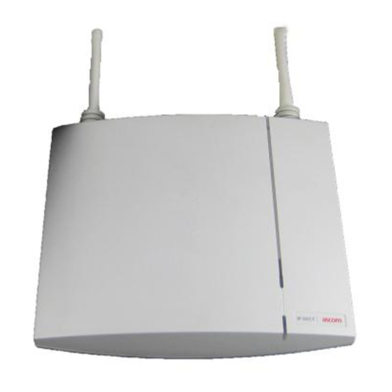
Page 7: Ipbs1 With External Antennas
Installation Guide TD 92989EN IP-DECT Base Station & IP-DECT Gateway 2.1.2 IPBS1 with External Antennas The IPBS1 is available with two omni-directional external antennas. Other external antennas can be mounted as well. This section contains the differences between the IPBS1 with internal and external antennas. -
Page 8: Ipbs2
Installation Guide TD 92989EN IP-DECT Base Station & IP-DECT Gateway IPBS2 The following versions of the IPBS2 are available: • IPBS2 with internal antenna • IPBS2 with external antennas The IPBS2 is backward compatible with the IPBS1 when it comes to coverage, functionality, accessories and mounting bracket. - Page 9 Installation Guide TD 92989EN IP-DECT Base Station & IP-DECT Gateway Power Distribution The IPBS2 can be powered using the following methods: • Power over Ethernet, IEEE 802.3af • A local AC-adapter NOTE: For more information about power distribution, see 3.3 Power the Base Station page 25.
-
Page 10: Ipbs2 With External Antennas
Installation Guide TD 92989EN IP-DECT Base Station & IP-DECT Gateway Mini firmware 100 ms yellow, 100 ms off. The IPBS2 is in mini firmware mode. TFTP mode Solid yellow. TFTP mode. Error 100 ms red, 100 ms off. No Ethernet connection. Fatal error Solid red. - Page 11 Installation Guide TD 92989EN IP-DECT Base Station & IP-DECT Gateway Contents of the Box The box in which the IPBS2 is packed contains: • An IPBS2 with external antennas. • A mounting bracket • An antenna bracket • Two antenna coaxial cables. •...
-
Page 12: Ipbl
Installation Guide TD 92989EN IP-DECT Base Station & IP-DECT Gateway IPBL The following versions of the IPBL are available: • IPBL IP-DECT Gateway VAC/VDC (for 110/230 VAC or 48 VDC) • IPBL IP-DECT Gateway VDC (for 48 VDC) 2.3.1 Overview base station synchronization reference... -
Page 13: Led Indication
Installation Guide TD 92989EN IP-DECT Base Station & IP-DECT Gateway 2.3.3 LED indication Status LED Description Not lit Not powered, status is not defined. Flashing slow green When pressing the reset button. Flashing fast green Firmware update or clear config after long reset. Steady green Status OK, system is fully operational. - Page 14 Installation Guide TD 92989EN IP-DECT Base Station & IP-DECT Gateway Not lit 10 Mbps operation. Steady 100 Mbps operation. 15 October 2014 / Ver. B...
-
Page 15: Bs3X0
Installation Guide TD 92989EN IP-DECT Base Station & IP-DECT Gateway BS3x0 The following versions are available: • BS330 with Internal antenna • BS340 with External antennas Front view Back view LED2 LED1 Data/Power Data/Power Test (RJ12) (RJ45) (RJ45) Figure 5. BS3x0 Overview Contents of the Box The box in which the base station is packed contains: •... - Page 16 Installation Guide TD 92989EN IP-DECT Base Station & IP-DECT Gateway Software The software in the BS3x0 can be updated by downloading new software without disconnecting the equipment. The new software is stored in flash memory. For information on how to update the software in the BS3x0, see the applicable Installation and Operation Manual for the BS3x0.
-
Page 17: Db1
Installation Guide TD 92989EN IP-DECT Base Station & IP-DECT Gateway The following versions of the DB1 are available: • DB1 with internal antenna • DB1 with external antennas The DB1 is backward compatible with the BS3x0 when it comes to coverage, functionality, accessories and mounting bracket. - Page 18 Installation Guide TD 92989EN IP-DECT Base Station & IP-DECT Gateway Power Distribution The DB1 can be powered using the following methods: • From the IPBL via the Express Powering Pair (EPP) and data pairs • With a local AC-adapter NOTE: For more information about power distribution, see 3.3 Power the Base Station page 25.
-
Page 19: Db1 With External Antennas
Installation Guide TD 92989EN IP-DECT Base Station & IP-DECT Gateway Error 100 ms red, 100 ms off. layer 1 communication error. Fatal error Solid red. Fatal hardware error. DIP Switches The DIP switches can be found on the back of the DB1, see figure 6 on page 14. -
Page 20: Ac-Adapter
Installation Guide TD 92989EN IP-DECT Base Station & IP-DECT Gateway • Four screws with wall plugs AC-adapter The AC-adapter is used to power a base station locally. NOTE: The maximum length of cable from adapter must not exceed 10 meters. Versions (different type of mains plug) For European countries except U.K. -
Page 21: Installation Of The Base Station
Installation Guide TD 92989EN IP-DECT Base Station & IP-DECT Gateway Installation of the Base Station This section describes how to install the IPBSs, BS3x0 and DB1. All three base stations can be fixed to a wall, a ceiling, a pole or a beam, by means of the mounting bracket included. When fixing the base station to a wall or ceiling the included plugs and screws must be used. -
Page 22: Fix The Mounting Bracket To A Ceiling
Installation Guide TD 92989EN IP-DECT Base Station & IP-DECT Gateway Ceiling 65 mm (IPBS1, BS3x0) 100 mm (IPBS2, DB1) Figure 8. Fixing the mounting bracket to a wall. 3.2.2 Fix the Mounting Bracket to a Ceiling Fixing to a ceiling is done in the same way as the a wall, see 3.2.1 Fix the Mounting Bracket to a Wall. -
Page 23: Use The Cable Ducts For Ipbs1
Installation Guide TD 92989EN IP-DECT Base Station & IP-DECT Gateway Tied wrongly Figure 9. Fixing the mounting bracket to a pole or beam. 3.2.4 Use the Cable Ducts for IPBS1 When the base station IPBS1 is mounted to the wall, cable ducts can be used to route the wiring through. -
Page 24: Connect External Antennas (Only Ipbs2 And Db1)
Installation Guide TD 92989EN IP-DECT Base Station & IP-DECT Gateway 65 mm 57 mm 125 mm 75 mm 70 mm 15 mm thick cable ducts Figure 10. Minimum distances between a cable duct and the mounting bracket 3.2.5 Connect External Antennas (only IPBS2 and DB1) Position the included antenna bracket above the mounting bracket with a minimum distance of 74 mm (250 mm maximum) and mark the two holes for the antenna bracket, see... - Page 25 Installation Guide TD 92989EN IP-DECT Base Station & IP-DECT Gateway Connect the coaxial cables to the MCX connectors on the base station. Back view while lying down MCX connectors Mount the base station (3), see 3.2.9 Mount the Base Station on page 24.
-
Page 26: Secure The Cable
Installation Guide TD 92989EN IP-DECT Base Station & IP-DECT Gateway 3.2.6 Secure the Cable For safety reasons secure the base station cable to a convenient point at about 30 cm from the base station. If for some reason the base station drops, it is secured by the cable. 3.2.7 Pinning Cut the cable to the correct length and connect the cable to a RJ45 modular jack. -
Page 27: Connect The Base Station Cables
Installation Guide TD 92989EN IP-DECT Base Station & IP-DECT Gateway Pin the BS3x0/DB1 Cable RJ45 modular jack SC = Serial Channel EPP = Express Power Pairs NC = Not Connected Figure 14. Connector pinning of the Data connector IMPORTANT: If local power supply is used, the EPP cable pair must NOT be connected. 3.2.8 Connect the Base Station Cables Only for IPBS1: If it is required that the cables enter the base station centrally from... -
Page 28: Power The Base Station
Installation Guide TD 92989EN IP-DECT Base Station & IP-DECT Gateway Figure 15. Mounting of the IPBS. Power the Base Station The base station is powered the following ways: • Power over Ethernet (only IPBS). • Power over Express Powering Pairs (EPP) and data pairs (only BS3x0 and DB1) •... - Page 29 Installation Guide TD 92989EN IP-DECT Base Station & IP-DECT Gateway NOTE: Only approved power supply according to valid editions of EN/IEC/CSA/UL/AU/NZS 60950 is to be used when the base station is powered by a local power supply. 15 October 2014 / Ver. B...
-
Page 30: Installation Of The Ipbl
Installation Guide TD 92989EN IP-DECT Base Station & IP-DECT Gateway Installation of the IPBL This section describes how to install the IPBL. Install the IPBL IMPORTANT: To keep the same functionality of the system, do not mix different RFPs, Core (KRCNB 201) with Worf (KRCNB 30x and BS3x0), on the same IPBL. The reason this will not work is prolonged preamle is supported by Worf RFPs but not by Core RFPs. - Page 31 Installation Guide TD 92989EN IP-DECT Base Station & IP-DECT Gateway Make sure that the total current consumption does not exceeds the following values: • Max current consumption is 1,9/0,9 A when supplied with 110/230 VAC. • Max current consumption is 5,2 A when supplied with 48 VDC. ...
-
Page 32: Pin The Ipbl Cable
Installation Guide TD 92989EN IP-DECT Base Station & IP-DECT Gateway Pin the IPBL Cable All data cables used for the IPBL is standard CAT5 unshielded cable. It is assumed that installation personnel know how to crimp these connectors to a cable. 4.2.1 Synchronization Cable The maximum cable length between two IPBLs must not exceed 2000 meters. -
Page 33: Rfp Cable
Installation Guide TD 92989EN IP-DECT Base Station & IP-DECT Gateway 4.2.2 RFP Cable The RFP cable connects the IPBL with the RFPs. The maximum cable length between IPBL and a single RFP must not exceed 1500 meters. NOTE: Ensure that during the installation, each RFP is given an extra length (5-10 metres) of cable because it is possible that it will have to be moved for one reason or another. -
Page 34: Power The Ipbl
Installation Guide TD 92989EN IP-DECT Base Station & IP-DECT Gateway Power the IPBL The IPBL power supply connectors are located at the rear. The power supply feeds both the IPBL and the connected RFPs. There are two alternatives to power the IPBL: •... -
Page 35: 48 Vdc
Installation Guide TD 92989EN IP-DECT Base Station & IP-DECT Gateway 4.3.2 48 VDC The 48 VDC (42 – 56 VDC) power input includes a fuse on the 48 VDC input to protect against overload. The IPBL also has a protection circuit to protect both the IPBL and the external power supply from damages caused by the user reversing the input terminals during installation. -
Page 36: Related Documents
Installation Guide TD 92989EN IP-DECT Base Station & IP-DECT Gateway Related Documents Installation and Operation Manual for IP-DECT Base Station and IP-DECT TD 92579EN Gateway 15 October 2014 / Ver. B... - Page 37 Installation Guide TD 92989EN IP-DECT Base Station & IP-DECT Gateway Document History For details in the latest version, see change bars in the document. Version Date Description Ver. A 31 May 2013 First released version. 15 October 2014 Updated section DIP Switches on page 16.
-
Page 38: Appendix A. Rfp Power Consumption
Installation Guide TD 92989EN IP-DECT Base Station & IP-DECT Gateway Appendix A. RFP Power Consumption The tables below show power consumption for a base station connected to and powered from the IPBL. The maximum cable length for base stations connected to the IPBL must not exceed 1500 meters. - Page 39 Installation Guide TD 92989EN IP-DECT Base Station & IP-DECT Gateway A.2 BS3x0 and DB1 Cable 0.4 mm 0.4 mm 0.5 mm 0.5 mm 0.6 mm 0.6 mm length wire size wire size wire size wire size wire size wire size (metres) () ()
Need help?
Do you have a question about the IP-DECT IPBS1 and is the answer not in the manual?
Questions and answers