Table of Contents
Advertisement
Quick Links
Chapter 16
16.1
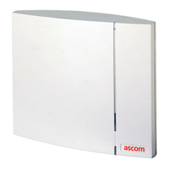
General
The base station is connected to the radio exchange by means of a standard twisted pair cable. The base station
is can be fixed to a wall, a ceiling, a pole or a beam, by means of the mounting bracket included. When fixing
the base station to a wall or ceiling the included plugs and screws must be used. When fixing it to a pole or beam
a (not included) strap a flexible metal band must be used.
Versions
The following versions of the BS330 are available:
•
BS330/STD: 1880 – 1900 MHz
•
BS330/CHINA: 1900 – 1920 MHz
•
BS330/LA: 1910 – 1930 MHz
•
BS330/US&CDA: 1920 – 1930 MHz
Contents of the box
The box in which the base station is packed contains:
•
A base station
•
A mounting bracket
•
Two screws with wall plugs
Note:
The brand label is not included in the box, but must be ordered separately.
Power distribution
Base stations can be powered by the following sources:
•
The radio exchange via the data pairs
•
The radio exchange via the data and Express Powering Pairs (EPP)
•
A 48 V external supply connected to the radio exchange
•
A local AC-adapter
Note:
For more information about power distribution, refer to the section 'Configuration directions'.
AC-adapter for a base station
A 24 Vdc adapter (BMLNB 101 09/n) can be used. This adapter is provided with an 8-pin RJ45 plug that can
be plugged into one of the data/power connectors of the base station.
Software
If necessary, the software in the base station can be updated by downloading new software to the base station.
Downloading can be performed without disconnecting the base stations. The new software is stored in flash
memory. How to download the software is described in the help file of the application Cordless System Manager
(CSM) for Windows.
TD 92093 (1/LZBNB 103 108 R4D) / 2005-09-23/ Ver.C
2005
BS330 base station
Technical Product Manual - DCT1800-GAP
Installation instructions, BS330 base station
63
Advertisement
Table of Contents

Related Manuals for ASCOM BS330


Summary of Contents for ASCOM BS330
- Page 1 When fixing it to a pole or beam a (not included) strap a flexible metal band must be used. Versions The following versions of the BS330 are available: • BS330/STD: 1880 – 1900 MHz •...
-
Page 2: Front View
Technical Product Manual - DCT1800-GAP Installation instructions, BS330 base station Connectors • Two 8-pin RJ45 modular jacks for data and powering • A 6-pin RJ12 modular jack for factory testing The two data/powering connectors are interconnected on the board. LEDs... -
Page 3: Base Station Cabling
Technical Product Manual - DCT1800-GAP Installation instructions, BS330 base station 16.2 Base station cabling The base station cable must be a twisted pair cable with 2 pairs minimum for connection of the data lines. Also power can be distributed via these data pairs. - Page 4 Technical Product Manual - DCT1800-GAP Installation instructions, BS330 base station 16.3.1 Fixing the mounting bracket to a wall Fix the mounting bracket (see figure 37) to the wall as follows: Hold the mounting bracket with its flat side against the wall such that the text ‘TOP’ is the right way up, and mark the two holes.
- Page 5 Technical Product Manual - DCT1800-GAP Installation instructions, BS330 base station 16.3.2 Fixing the mounting bracket to a ceiling Fixing to a ceiling is done in the same way as the a wall (see paragraph 16.3.1). When the base station has to be positioned above a suspended ceiling, take care that the front of the base station points downwards.
- Page 6 Technical Product Manual - DCT1800-GAP Installation instructions, BS330 base station Fix the cable duct to the wall in one of the positions shown in figure 39. 65 mm 57 mm 125 mm 75 mm 70 mm 15 mm thick cable ducts Fig.
- Page 7 Technical Product Manual - DCT1800-GAP Installation instructions, BS330 base station RJ45 modular jack SC = Serial Channel EPP = Express Power Pair NC = Not connected Fig. 40 Connector pinning of the data/power connector 16.3.7 Base station cable delay measurement...
-
Page 8: Mounting The Base Station
Technical Product Manual - DCT1800-GAP Installation instructions, BS330 base station Stick the brand label in the front cover recess. 16.3.9 Connecting the base station cables If it is required that the cables enter the base station centrally from above, guide the cables through the recess in the middle of the base station as shown in figure 41. - Page 9 Technical Product Manual - DCT1800-GAP Installation instructions, BS330 base station Fig. 42 Mounting the base station TD 92093 (1/LZBNB 103 108 R4D) / 2005-09-23/ Ver.C 2005...
- Page 10 Technical Product Manual - DCT1800-GAP Installation instructions, BS330 base station TD 92093 (1/LZBNB 103 108 R4D) / 2005-09-23/ Ver.C 2005...
Need help?
Do you have a question about the BS330 and is the answer not in the manual?
Questions and answers