Vari Lite VL2000 User Manual
Spot luminaire
Hide thumbs
Also See for VL2000:
- Service manual (190 pages) ,
- User manual (115 pages) ,
- Service manual (180 pages)
Table of Contents
Advertisement
Advertisement
Table of Contents
Troubleshooting

Related Manuals for Vari Lite VL2000


Summary of Contents for Vari Lite VL2000
-
Page 2: Table Of Contents
Chapter 1. Description Features Overview........................4 Components Included Items......................5 Replacement Items/Accessories................... 5 VL2000 Spot Luminaire ....................6 LED Indicators......................7 Chapter 2. Installation Power and Data Cabling Requirements Power ......................... 10 Current vs. Voltage....................11 Data Cables ........................ 12 Recommended Cable Types/Manufacturers............ - Page 3 ❋ VARI LITE® - VL2000™ S ’ UMINAIRE ANUAL Chapter 3. Operation Color/Gobo Control Color/Gobo Wheel Positions ..................26 Standard Colors and Gobos..................26 DMX Modes 8-Bit and 16-Bit Modes....................28 DMX Mapping Color and Gobo Control..................... 29 Beam Control ......................33 Luminaire Timing Luminaire Timing Channel Information..............
- Page 4 ABLE OF ONTENTS Appendix A. Troubleshooting and Maintenance Troubleshooting Error Messages......................78 Troubleshooting Guide....................79 Routine Maintenance Lamp Replacement ....................83 Color Filter Replacement ................... 85 Fixed Gobo Replacement................... 87 Rotating Gobo Replacement ..................89 Cleaning Optical Lenses and Filters ................91 Appendix B.
- Page 5 ❋ VARI LITE® - VL2000™ S ’ UMINAIRE ANUAL Notes 02-May-03 02 .9 673 .00 01 D...
-
Page 6: Introduction
Source VL2000™ Spot Luminaire 20.9673.0001 Additional Documentation A service manual for extended maintenance of the VL2000 spot luminaire is available in both printed and electronic (PDF) formats: • VL2000 Spot Luminaire Service Manual (02.9673.0010) - Testing, Troubleshooting, Component Replacement and Illustrated Parts Breakdown. -
Page 7: Text Conventions
Customer Service Our Goal At Vari-Lite, we are committed to providing you the highest quality in customer service. Our comprehensive resources are available to help your business succeed and ensure you get the full benefit of being a Vari-Lite customer. Whether your needs are telephone troubleshooting assistance, product training or technical service, our full-time staff of experienced professionals are on-hand to provide support. -
Page 8: Chapter 1. Description
HAPTER Description This chapter contains descriptions of luminaire features and components, along with a list of accessories which are available. • Features • Components 02.96 73.000 1 D 02-May-03... -
Page 9: Features
LITE® - VL2000™ S ’ UMINAIRE ANUAL Features Overview The VL2000 spot luminaire contains the following standard features: • Variable beam focus to soften the edges of gobos or spots and enable gobo morphing. • Full field dimmer to allow smooth timed fades and fast blackouts. -
Page 10: Components
User’s Manual VL2000 Spot Luminaire Mounting Brackets Figure 1-1: VL2000 Spot Luminaire Packing List Replacement Items/Accessories The following optional and/or replacement items can be ordered directly from Vari-Lite. (Please order by Vari-Lite part number.) Vari-Lite Part No. Accessory 20.9625.0132 Plastic Road Case (Two Hole) 22.9620.0194... -
Page 11: Vl2000 Spot Luminaire
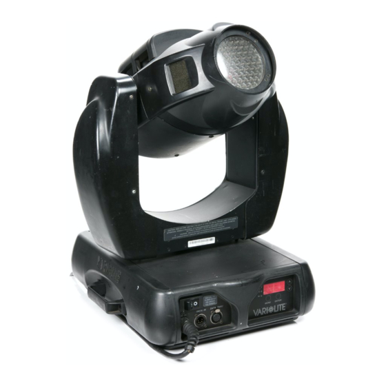
❋ VARI LITE® - VL2000™ S ’ UMINAIRE ANUAL VL2000 Spot Luminaire The following illustration shows the major luminaire components and controls. Removable Lamp Assembly Truss Hook (to access lamp for replacement) Bracket Assembly Upper Enclosure Assembly AC Input Cable... -
Page 12: Led Indicators
ESCRIPTION OMPONENTS LED Indicators The LED indicators report the status of power and data to the luminaire. Indicates DC power is being supplied via AC Input when lit Indicates data is being transmitted when flashing Indicates data is being received when flashing fast; when flashing in 2 sec. - Page 13 ❋ VARI LITE® - VL2000™ S ’ UMINAIRE ANUAL Notes 02-May-03 02 .9 673 .00 01 D...
-
Page 14: Chapter 2. Installation
HAPTER Installation This chapter contains instructions for installation of the luminaire. It includes connecting power and data, along with instructions for powering up the luminaire for the first time and addressing it within your system. • Power and Data Cabling Requirements •... -
Page 15: Power And Data Cabling Requirements
❋ VARI LITE® - VL2000™ S ’ UMINAIRE ANUAL Power and Data Cabling Requirements Power The luminaire requires standard AC power distribution from 100-240 VAC, 50/60 Hz. Three amps to twelve amps will be required depending on the AC supply voltage and product model. -
Page 16: Current Vs. Voltage
NSTALLATION OWER AND ABLING EQUIREMENTS Current vs. Voltage The following table provides the luminaire’s current draw at specific voltages. Current is calculated with the lamp on and all motors sequencing. Table 2-1: Current vs. Voltage Voltage @ 60Hz Current 90.0 11.8 100.0 10.6... -
Page 17: Data Cables
❋ VARI LITE® - VL2000™ S ’ UMINAIRE ANUAL Data Cables The luminaire is equipped with two, 5-pin XLR connectors for DATA IN and DATA THRU (out) applications. DATA IN requires a 5-pin, female XLR connector and DATA THRU requires a 5-pin, male XLR connector. -
Page 18: Recommended Cable Types/Manufacturers
NSTALLATION OWER AND ABLING EQUIREMENTS Recommended Cable Types/Manufacturers These are only a few of the suitable cable types. Any quality EIA485, twisted pair, 120 ohm, shielded cable will also work. ∗ Type Pairs Jacket Temp (F) ZΩ Belden Cables 1215A IBM Type 6 Office cable 1269A... -
Page 19: Male Termination Connector
5-pin, male XLR connector. pins 2 & 3, and 4 & 5 • Two 1/4W 5% 120 ohm resistors. Note: A male termination connector is available as an accessory from Vari-Lite. See “Replacement Items/Accessories” on page Loopback Connector When transferring software versions from luminaire to luminaire, a loopback connector is required at the first luminaire in the data link. -
Page 20: Installation Procedures
NSTALLATION NSTALLATION ROCEDURES Installation Procedures Installing Lamp In the event the lamp was packed separately during shipment, it will be necessary to install in the luminaire before use. WARNING: Ensure that power is removed from luminaire when installing lamp. CAUTION: Wear cotton gloves or other covering while installing lamp. Touching lamp glass with bare fingers will leave oil and may cause the lamp to explode or reduce lamp life. -
Page 21: Hanging The Luminaire
ANUAL Hanging the Luminaire The VL2000 spot luminaire can be hung horizontally or vertically from any structure designed to work with the type of load created by this moving luminaire. Two mounting bracket assemblies (provided) are used to attach truss hooks or other mounting hardware as required. Many compatible truss hooks are available from different manufacturers for your particular needs. - Page 22 NSTALLATION NSTALLATION ROCEDURES Step 3. While pulling up on locking mechanism release, fit keyed holes onto raised mounting buttons at bottom of enclosure. Slide forward and release locking mechanism to lock in place. Ensure brackets are locked securely. (Always face brackets in same direction as shown.) WARNING: Ensure that the bracket locking mechanism is fully seated after the bracket is installed on the luminaire.
- Page 23 ❋ VARI LITE® - VL2000™ S ’ UMINAIRE ANUAL Installing in Truss: Step 1. Using two people, lift luminaire into mounting position. Step 2. Secure in place with truss hook. Ensure truss hook hardware that locks hook in place (e.g.
-
Page 24: Floor Mounting The Luminaire
NSTALLATION NSTALLATION ROCEDURES Floor Mounting the Luminaire The luminaire enclosure is sufficient to stabilize the luminaire in a floor installation, provided that the mounting surface is flat and sturdy. Connecting Data and Power A maximum of 32 luminaires may be connected in any one DMX data link. Note: This maximum limit applies to the luminaire "daisy chain"... -
Page 25: Powering Up
❋ VARI LITE® - VL2000™ S ’ UMINAIRE ANUAL Powering Up Power-Up Procedure Since Lamp On is the default state, the lamp will strike when the luminaire is powered up for the first time. When AC power is applied, the luminaire will immediately begin a calibration sequence that steps it through full pan and tilt movements. -
Page 26: Align Lamp For Flat Field
OWERING Align Lamp for Flat Field The design of the VL2000 spot luminaire optical system is based on a flat field. A flat field is one where there is no detectable hot spot. After a new lamp is installed, it will be necessary to align the lamp to optimize the beam for the flat field. -
Page 27: Set Dmx Mode
❋ VARI LITE® - VL2000™ S ’ UMINAIRE ANUAL Set DMX Mode The luminaire provide four modes for DMX operation. The mode is set using the Menu Display. • 8-bit Standard - provides one 8-bit DMX channel for control of each luminaire function. -
Page 28: Addressing
NSTALLATION DDRESSING Addressing Program Starting Address The address setting for DMX console or Virtuoso console controlled systems is entered using the Menu Display. (Refer to “Menu System” chapter on page 47 for detailed instructions.) The luminaire retains the DMX and Virtuoso addresses that are stored even if power is removed. Note: Refer to your console operating instructions for specific information regarding its addressing requirements. - Page 29 ❋ VARI LITE® - VL2000™ S ’ UMINAIRE ANUAL Notes 02-May-03 02 .9 673 .00 01 D...
-
Page 30: Chapter 3. Operation
HAPTER Operation This chapter contains instructions for operating the luminaire using DMX control and for updating the internal software. • Color/Gobo Control • DMX Modes • DMX Mapping • Luminaire Timing • Updating Software 02.96 73.000 1 D 02-May-03... -
Page 31: Color/Gobo Control
❋ VARI LITE® - VL2000™ S ’ UMINAIRE ANUAL Color/Gobo Control Color/Gobo Wheel Positions The standard configurations for color and fixed gobo wheels Wheel 1 - Colors (Behind plate) are: all color filters installed on Wheel 1 (wheel nearest lamp) and all gobos installed on Wheel 2 (wheel nearer to front lens). - Page 32 PERATION OLOR ONTROL Standard Gobos - Wheel 2 (Fixed Gobo Wheel) Dust Medium Breakup Circles Pebbles Night Sky Leaves Block Wave Alpha Vertical Liquid Tribal Breakup Rays Bars Breakup Breakup Figure 3-3: Standard Gobos - Wheel 2 (Fixed Gobo Wheel) Standard Rotating Gobos open 5 Facet Prism...
-
Page 33: Dmx Modes
❋ VARI LITE® - VL2000™ S ’ UMINAIRE ANUAL DMX Modes 8-Bit and 16-Bit Modes These tables assume a DMX start address of 1. When a different starting address is used, this address becomes channel 1 function and other functions follow in sequence. -
Page 34: Dmx Mapping
: DMX M PERATION APPING DMX Mapping Color and Gobo Control Color/Gobo Wheels Table 3-1: DMX Map For Color/Gobo Wheels % Value DMX (0-255) Wheel Position Open Frame 1 Half Frame Full Frame 2 Half Frame 02.96 73.000 1 D 02-May-03... - Page 35 ❋ VARI LITE® - VL2000™ S ’ UMINAIRE ANUAL Table 3-1: DMX Map For Color/Gobo Wheels (Continued) % Value DMX (0-255) Wheel Position Full Frame 3 Half Frame Full Frame 4 Half Frame Full Frame 5 02-May-03 02 .9 673 .00 01 D...
- Page 36 : DMX M PERATION APPING Table 3-1: DMX Map For Color/Gobo Wheels (Continued) % Value DMX (0-255) Wheel Position Half Frame Full Frame 6 Half Frame Full Frame 7 Half Frame 02.96 73.000 1 D 02-May-03...
- Page 37 ❋ VARI LITE® - VL2000™ S ’ UMINAIRE ANUAL Table 3-1: DMX Map For Color/Gobo Wheels (Continued) % Value DMX (0-255) Wheel Position Full Frame 8 Half Frame Full Frame 9 Half Frame 02-May-03 02 .9 673 .00 01 D...
- Page 38 : DMX M PERATION APPING Table 3-1: DMX Map For Color/Gobo Wheels (Continued) % Value DMX (0-255) Wheel Position Full Frame 10 Half Frame Full Frame 11 Half Frame Full Frame 12 02.96 73.000 1 D 02-May-03...
- Page 39 ❋ VARI LITE® - VL2000™ S ’ UMINAIRE ANUAL Table 3-1: DMX Map For Color/Gobo Wheels (Continued) % Value DMX (0-255) Wheel Position Half Frame Spin F CCW Spin M CCW Spin S CCW Stop Stop Stop Spin S CW 02-May-03 02 .9 673 .00 01 D...
- Page 40 : DMX M PERATION APPING Table 3-1: DMX Map For Color/Gobo Wheels (Continued) % Value DMX (0-255) Wheel Position Spin M CW Spin F CW Rotating Gobo Index/Rotation Table 3-2: DMX Map for Gobo Index/Rotation % Value DMX (0-255) Wheel Position 0-84 0-215 Index Position...
-
Page 41: Beam Control
❋ VARI LITE® - VL2000™ S ’ UMINAIRE ANUAL Beam Control Beam Iris Table 3-4: DMX Map For Beam Iris % Value DMX Value Action Closed Open Edge Table 3-5: DMX Map For Edge % Value DMX Value Action Blooms In... -
Page 42: Luminaire Timing
PERATION UMINAIRE IMING Luminaire Timing Luminaire Timing Channel Information Timing channel control improves the timed moves of certain groups of parameters. We provide three timing channels, one for Focus (Pan and Tilt), one for color parameters and one for beam parameters. Timing channels support time values of up to six minutes. - Page 43 ❋ VARI LITE® - VL2000™ S ’ UMINAIRE ANUAL Table 3-9: Timing Channels Map % Value = Seconds Full Speed 02-May-03 02 .9 673 .00 01 D...
- Page 44 PERATION UMINAIRE IMING Table 3-9: Timing Channels Map (Continued) % Value = Seconds 10.2 10.4 10.6 02.96 73.000 1 D 02-May-03...
- Page 45 ❋ VARI LITE® - VL2000™ S ’ UMINAIRE ANUAL Table 3-9: Timing Channels Map (Continued) % Value = Seconds 02-May-03 02 .9 673 .00 01 D...
- Page 46 PERATION UMINAIRE IMING Table 3-9: Timing Channels Map (Continued) % Value = Seconds 02.96 73.000 1 D 02-May-03...
- Page 47 ❋ VARI LITE® - VL2000™ S ’ UMINAIRE ANUAL Table 3-9: Timing Channels Map (Continued) % Value = Seconds 02-May-03 02 .9 673 .00 01 D...
- Page 48 PERATION UMINAIRE IMING Table 3-9: Timing Channels Map (Continued) % Value = Seconds 02.96 73.000 1 D 02-May-03...
-
Page 49: Control Channel Functions
❋ VARI LITE® - VL2000™ S ’ UMINAIRE ANUAL Table 3-9: Timing Channels Map (Continued) % Value = Seconds Follows Cue Data Control Channel Functions The following control actions must be accomplished with zero time transition or with timing disabled. -
Page 50: Updating Software
The VL Download.exe program allows you to transfer new versions of the operating software (.bin files) to the luminaires via the PC. The VL Download.exe and current .bin files are available from the Product Downloads page at www.vari-lite.com. Instructions for installing the program on your PC are also available on the Product Downloads page. -
Page 51: Reprogramming Procedure
19. (Programming more than 32 luminaires will require programming in batches of 32 or less.) To update luminaire software: Step 1. From Product Downloads page at www.vari-lite.com, download and install the VLDownload.exe program and required .bin files onto your PC (following instructions at the website). - Page 52 PERATION PDATING OFTWARE Note: Version dates shown in this graphic are for illustration purposes only and may not correspond to the version you are downloading. Click to download all Click to download specific software listed software versions version to connected luminaire(s) to connected luminaire(s) Lists the specific versions of software that have been...
-
Page 53: Transferring Software From Luminaire To Luminaire
❋ VARI LITE® - VL2000™ S ’ UMINAIRE ANUAL Verify software version at luminaire: Step 1. At Menu Display, press [Menu]. Step 2. Press [Up] / [Down] arrows until Fixt appears. Press [Enter]. Step 3. Press [Up] / [Down] arrows until Ver appears. Press [Enter]. - Page 54 PERATION PDATING OFTWARE Step 3. At master luminaire Menu Display, press [Menu]. Step 4. Press [Up] / [Down] arrows until Fixture appears. Step 5. Press [Up] / [Down] arrows until Download appears. Press [Enter]. Step 6. OK? will be displayed. Press [Enter] to accept. Step 7.
- Page 55 ❋ VARI LITE® - VL2000™ S ’ UMINAIRE ANUAL Notes 02-May-03 02 .9 673 .00 01 D...
-
Page 56: Chapter 4. Menu System
HAPTER Menu System This chapter contains instructions for operating the luminaire using the Menu Display feature. • Operation • Display TestMapping • Cues and Sequences • Self Tests 02.96 73.000 1 D 02-May-03... -
Page 57: Operation
❋ VARI LITE® - VL2000™ S ’ UMINAIRE ANUAL Operation What Is the Menu System? The menu system is a programmable set of commands used to configure, address, operate, and test the luminaire. The menu system is controlled at the Menu Display available at the enclosure input panel. -
Page 58: Display Orientation
YSTEM PERATION To enter the menu system, first press [Menu]. The functions displayed will be 1st level functions. Scroll through the 1st level functions by pressing [Up] / [Down] arrows. Once the desired function appears in the display, press [Enter]. You are now at the 2nd level. Once again, press the [Up] / [Down] arrows to scroll through 2nd level functions. -
Page 59: Default State
❋ VARI LITE® - VL2000™ S ’ UMINAIRE ANUAL Default State The menu display’s default state during normal operation is to display the address (Virtuoso or DMX). After 10 seconds of inactivity at the display, it will change to the default state. -
Page 60: Shortcuts
YSTEM PERATION Shortcuts A few button combinations are provided as shortcuts for frequently used menu functions. These shortcuts are as follows: • Pressing [Enter] and [Up] at the same time = Lamp On • Pressing [Enter] and [Down] at the same time = Lamp Off •... -
Page 61: Menu System Overview
❋ VARI LITE® - VL2000™ S ’ UMINAIRE ANUAL Menu System Overview The following is a graphic representation of the entire menu system. value Addr Tilt value value Whl1 value VIRT value Whl2 value Iris value Dimm value LAMP POWR... -
Page 62: Menu System Functions
YSTEM PERATION Menu System Functions Table 4-1: Menu System Chart 1st Level 2nd Level 3rd Level 4th Level 5thLevel Addr DMX DMX Address XXX Address value Address VIRT Virtuoso Address XXXX. Address value LAMP Lamp Options POWR Lamp Power ON (default) System Configuration P UP Lamp Power-up State... - Page 63 ❋ VARI LITE® - VL2000™ S ’ UMINAIRE ANUAL Table 4-1: Menu System Chart (Continued) 1st Level 2nd Level 3rd Level 4th Level 5thLevel Fixt STAT Status/Error Display Scrolls error messages * or displays OK Cal Recalibrate Modl Luminaire Model Type...
- Page 64 YSTEM PERATION Table 4-1: Menu System Chart (Continued) 1st Level 2nd Level 3rd Level 4th Level 5thLevel FLTM Follow Time XXX.X Data Stor Store Cue XX Cue # to Store Processing (Not editable – given next cue ID in list) Mod Modify Cue XX List of Cues Del Delete Cue...
- Page 65 ❋ VARI LITE® - VL2000™ S ’ UMINAIRE ANUAL Table 4-1: Menu System Chart (Continued) 1st Level 2nd Level 3rd Level 4th Level 5thLevel Test (cont.) FGob Fixed Gobo Wheel FG 1 Fixed Gobo Wheel Press [Menu] to Test stop tests...
-
Page 66: Function Definitions
YSTEM PERATION Function Definitions Each menu item is listed in the first column by its display abbreviation. The abbreviations appear in alphabetical order as opposed to their position in the menu display sequence for easy reference. Table 4-2: Menu Fuction Definitions Display Definition Purpose... - Page 67 ❋ VARI LITE® - VL2000™ S ’ UMINAIRE ANUAL Table 4-2: Menu Fuction Definitions (Continued) Display Definition Purpose Accesses functions for setting DMX mode or pan/tilt options (1st level menu) or sets starting address for luminaire in DMX systems (Addr).
- Page 68 YSTEM PERATION Table 4-2: Menu Fuction Definitions (Continued) Display Definition Purpose MODE DMX Mode Accesses functions for setting DMX mode to standard or enhanced 8-bit or 16-bit. Modl Model Displays model number of luminaire. For example, 2413 (VL2413). Move Move Enables and disables pan and tilt movement and auto-correction.
- Page 69 ❋ VARI LITE® - VL2000™ S ’ UMINAIRE ANUAL Table 4-2: Menu Fuction Definitions (Continued) Display Definition Purpose Tilt Tilt Specifies tilt function for manual control (Man) or tilt encoder for testing (Test). Time Timing Data Allows manual setting of timing values for dimmer/intensity, focus, color, and beam.
-
Page 70: Cues And Sequences
YSTEM UES AND EQUENCES Cues and Sequences Overview The luminaire has the ability to store and playback cues independent of a console. Cues are stored as numbers from 1 to 99 by using the Cue (Cue Processing) functions available in the menu system. This also allows you to create your own test sequences to be played back on a group of luminaires. -
Page 71: Cue Operations
❋ VARI LITE® - VL2000™ S ’ UMINAIRE ANUAL Cue Operations The following section provides instructions for performing cue, sequence, and playback operations. Note: The Mod, Del, PCue, PSEQ commands will all display "---" if no cues have been stored. - Page 72 YSTEM UES AND EQUENCES To store a cue: Step 1. Press [Menu]. Step 2. Press [Up] / [Down] arrows until Cue appears. Press [Enter]. Step 3. Press [Up] / [Down] arrows until Stor appears. Press [Enter]. The number displayed is the cue number to be stored.
- Page 73 ❋ VARI LITE® - VL2000™ S ’ UMINAIRE ANUAL To change the follow time in a sequence: The follow time is stored for each cue individually. Step 1. Select cue to be changed from PCue. Step 2. Go to Mod to modify active cue and press [Enter] to save the change.
-
Page 74: Self Tests
YSTEM ESTS Self Tests Running Parameter Tests The luminaire is capable of running self tests by using the TEST menu functions. For complete details and values for each test refer to “Diagnostic Tests” on page Note: After 10 seconds of inactivity, the menu display will change to the default state showing the address. - Page 75 ❋ VARI LITE® - VL2000™ S ’ UMINAIRE ANUAL Movement Disable The Movement option allows pan and tilt to be disabled so that the luminaire can be placed in any position for testing without movement occurring. In order to regain full control of the luminaire, Movement will need to be enabled after testing.
-
Page 76: Diagnostic Tests
YSTEM ESTS Diagnostic Tests The following diagnostic tests are available in the test menu. Time is specified for each action in the test, and the total time equals the time it takes to complete each action. If the time is zero the luminaire will perform the test at full speed. - Page 77 ❋ VARI LITE® - VL2000™ S ’ UMINAIRE ANUAL Table 4-3: Diagnostic DMX Values Parameters Test Name Inde Pan* Tilt* Iris Edge time/total time ALL1 65535 65535 ALL2 65535 65535 65535 65535 7/7 (P/T only) 65535 65535 7/7 (P/T only)
- Page 78 YSTEM ESTS Table 4-3: Diagnostic DMX Values (Continued) Parameters Test Name Inde Pan* Tilt* Iris Edge time/total time ALL2 45167 27000 (cont.) 45167 27000 45167 27000 45167 27000 45167 27000 45167 27000 45167 27000 45167 27000 45167 27000 45167 27000 45167 27000 45167...
- Page 79 ❋ VARI LITE® - VL2000™ S ’ UMINAIRE ANUAL Table 4-3: Diagnostic DMX Values (Continued) Parameters Test Name Inde Pan* Tilt* Iris Edge time/total time Pan3 33511 54957 22227 54957 35511 54957 22227 54957 44423 54957 39401 54957 44423 54957...
- Page 80 YSTEM ESTS Table 4-3: Diagnostic DMX Values (Continued) Parameters Test Name Inde Pan* Tilt* Iris Edge time/total time Dim3 45167 27000 0/0.5 45167 27000 0/0.5 45167 27000 0/0.5 45167 27000 0/0.5 45167 27000 0/0.5 45167 27000 0/0.5 45167 27000 0/0.5 45167 27000 0/0.5...
- Page 81 ❋ VARI LITE® - VL2000™ S ’ UMINAIRE ANUAL Table 4-3: Diagnostic DMX Values (Continued) Parameters Test Name Inde Pan* Tilt* Iris Edge time/total time Cwl1 45167 27000 45167 27000 45167 27000 45167 27000 45167 27000 45167 27000 45167 27000...
- Page 82 YSTEM ESTS Table 4-3: Diagnostic DMX Values (Continued) Parameters Test Name Inde Pan* Tilt* Iris Edge time/total time FG 1 45167 27000 45167 27000 45167 27000 45167 27000 45167 27000 45167 27000 45167 27000 45167 27000 45167 27000 45167 27000 45167 27000 45167...
- Page 83 ❋ VARI LITE® - VL2000™ S ’ UMINAIRE ANUAL Table 4-3: Diagnostic DMX Values (Continued) Parameters Test Name Inde Pan* Tilt* Iris Edge time/total time RG 1 45167 27000 45167 27000 45167 27000 45167 27000 45167 27000 45167 27000 RG 2...
- Page 84 YSTEM ESTS Table 4-3: Diagnostic DMX Values (Continued) Parameters Test Name Inde Pan* Tilt* Iris Edge time/total time Zm 1 45167 27000 45167 27000 45167 27000 45167 27000 Zm 3 45167 27000 45167 27000 45167 27000 45167 27000 45167 27000 45167 27000 *Pan and Tilt values are 16-bit DMX and will be different from the values in the Man control display.
- Page 85 ❋ VARI LITE® - VL2000™ S ’ UMINAIRE ANUAL Notes 02-May-03 02 .9 673 .00 01 D...
-
Page 86: Appendix A. Troubleshooting And Maintenance
PPENDIX Troubleshooting and Maintenance This appendix provides instructions for troubleshooting and performing routine maintenance which may be necessary during the life of the luminaire. • Troubleshooting • Routine Maintenance WARNING: All maintenance procedures are to be performed with power removed from the luminaire. -
Page 87: Troubleshooting
❋ VARI LITE® - VL2000™ S ’ UMINAIRE ANUAL Troubleshooting Error Messages If a problem occurs during luminaire calibration, at the end of the calibration sequence the Menu Display will cycle through any applicable error message(s), one a time until the end of the list is reached. -
Page 88: Troubleshooting Guide
CAUTION: Some troubleshooting is included for reference only. Performing remedies marked by gray areas will void product warranty. Refer to the Vari-Lite Limited Warranty card included with the product. - Page 89 ❋ VARI LITE® - VL2000™ S ’ UMINAIRE ANUAL Table A-2: Troubleshooting Guide (Continued) Error Display Description Possible Cause and Remedy B1M3 Aux Board 1, Motor 3, Wheel 1 power not connected, motor not moving Whl1 Wheel 1, - Connect wheel 1 power at motor...
- Page 90 ROUBLESHOOTING AND AINTENANCE Table A-2: Troubleshooting Guide (Continued) Error Display Description Possible Cause and Remedy BRD1 Aux Board 1 Communication Aux input connector (J5) not connected to either aux Failure board COMM - Connect aux input connector (J5) to either aux board Jumper/bridge connector (J1) between aux boards not connected...
- Page 91 ❋ VARI LITE® - VL2000™ S ’ UMINAIRE ANUAL Table A-2: Troubleshooting Guide (Continued) Error Display Description Possible Cause and Remedy TILT Tilt Sensor Not Found EOT flag attached to large pulley is not engaging the EOT sensor SENS - Ensure flag is attached to the large pulley...
-
Page 92: Routine Maintenance
ROUBLESHOOTING AND AINTENANCE Routine Maintenance Lamp Replacement WARNING: Remove power from luminaire before performing maintenance. Tools: Screwdriver, slotted Cotton gloves To replace lamp: Step 1. Remove power from luminaire. WARNING: Lamps will be extremely HOT after operation. Allow lamp to cool before replacing. Step 2. - Page 93 ❋ VARI LITE® - VL2000™ S ’ UMINAIRE ANUAL CAUTION: Wear cotton gloves or other covering while servicing lamp. Touching lamp glass with bare fingers will leave oil and may cause the lamp to explode or reduce lamp life. If required, use alcohol and cotton cloth to thoroughly clean glass portion of lamp.
-
Page 94: Color Filter Replacement
ROUBLESHOOTING AND AINTENANCE Color Filter Replacement WARNING: Remove power from luminaire before performing maintenance. Tools: Screwdriver, Phillips #2 Cotton gloves To remove and replace a color filter: Step 1. Remove power from luminaire. Step 2. At removable cover, using #2 Phillips screwdriver, turn two captive screws one-quarter turn and remove cover. - Page 95 ❋ VARI LITE® - VL2000™ S ’ UMINAIRE ANUAL Note: In some cases it is easier to slide bulkhead partially out of head assembly to access color filters. To do this, use #2 Phillips screwdriver to turn captive screw one-quarter turn and slide bulkhead upward.
-
Page 96: Fixed Gobo Replacement
ROUBLESHOOTING AND AINTENANCE Fixed Gobo Replacement WARNING: Remove power from luminaire before performing maintenance. Tools: Screwdriver, Phillips #2 Cotton gloves To remove and replace a fixed wheel gobo: Step 1. Remove power from luminaire. Step 2. At removable cover, using #2 Phillips screwdriver, turn two captive screws one-quarter turn and remove cover. - Page 97 ❋ VARI LITE® - VL2000™ S ’ UMINAIRE ANUAL CAUTION: Do not touch gobos with bare fingers. Wear cotton gloves or other covering while replacing. Clean with glass cleaner and soft cloth if required. Note: In some cases it is easier to slide bulkhead partially out of head assembly to access gobos. To do this, use #2 Phillips screwdriver to turn captive screw one-quarter turn and slide bulkhead upward.
-
Page 98: Rotating Gobo Replacement
ROUBLESHOOTING AND AINTENANCE Rotating Gobo Replacement WARNING: Remove power from luminaire before performing maintenance. Tools: Screwdriver, Phillips #2 Hook and Pick tool (or small slotted screwdriver) Cotton gloves To remove and replace a rotating gobo: Step 1. Remove power from luminaire. Step 2. - Page 99 ❋ VARI LITE® - VL2000™ S ’ UMINAIRE ANUAL Step 3. At rotating gobo wheel, rotate until required gobo/filter is accessible. Step 4. Locate end of coiled spring which is fitted under carrier tab. Using hook and pick tool or small slotted screwdriver, push end of spring from under tab until it is free.
-
Page 100: Cleaning Optical Lenses And Filters
ROUBLESHOOTING AND AINTENANCE Cleaning Optical Lenses and Filters WARNING: Remove power from luminaire before performing maintenance. The front lens, color filters, and gobos may require cleaning after extended use. A common glass cleaner can be used along with a soft, lint-free cloth to clean these components. CAUTION: Do not continuously rub filters or it may damage or remove the optical coating.
Need help?
Do you have a question about the VL2000 and is the answer not in the manual?
Questions and answers