
Subscribe to Our Youtube Channel
Related Manuals for Vari Lite VL4000


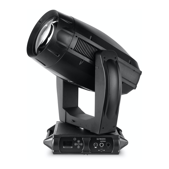
Summary of Contents for Vari Lite VL4000
- Page 1 22 April 2015 (Preliminary Release Version) VL4000 BeamWash Luminaire Service Manual...
- Page 2 This manual is for informational use only and is subject to change without notice. Philips Vari-Lite assumes no responsibility or liability for any claims resulting from errors or inaccuracies that may appear in this manual. Version as of: 22 April 2015 (Preliminary Release Version) Part number: 02.9704.6010 0 VL4000 BeamWash Luminaire Service Manual ©2015, Vari-Lite, a Philips group company. All Rights Reserved.
- Page 3 OREWORD How To Obtain Warranty Service A copy of the Vari-Lite Limited Warranty was included in the shipping package for this VARI❋LITE product. To obtain warranty service, please contact customer service at 1-877-VARI-LITE (1-877-827-4548), +1-214-647-7880, or entertainment.service@philips.com and request a Return Material Authorization (RMA) for warranty service.
- Page 4 ❋ VARI LITE - VL4000 B UMINAIRE ERVICE ANUAL Compliance Notice This equipment has been tested and found to comply with the limits for a Class A digital device pursuant to Part 15 of FCC Rules. These limits are designed to provide reasonable protection against harmful interference when this equipment is operated in a commercial environment.
- Page 5 WARNING: INSTRUCTIONS FOR CONTINUED PROTECTION AGAINST FIRE 1. VARI❋LITE luminaires have been designed for use with specific lamp types. VL4000 BeamWash Luminaires is supplied with an 1200W Philips MSR Gold FastFit lamp or other lamps as approved by Vari-Lite. Installing another type of lamp not approved by Vari-Lite may be hazardous.
- Page 6 ❋ VARI LITE - VL4000 B UMINAIRE ERVICE ANUAL WARNING: INSTRUCTIONS FOR CONTINUED PROTECTION AGAINST EXCESSIVE EXPOSURE TO UV RADIATION 1. Many VARI❋LITE luminaires use a lamp that produces UV radiation. DO NOT look directly at lamp. 2. It is hazardous to operate luminaires without lens or shield. Shields, lenses, or ultraviolet screens shall be changed if they have become visibly damaged to such an extent that their effectiveness is impaired.
- Page 7 OREWORD Sicherheitshinweise Es ist äußerst wichtig, ALLE Sicherheitsinformationen und -hinweise in diesem Handbuch und dem beiliegenden Informationsmaterial zu lesen, bevor Sie die hierin beschriebenen Produkte installieren bzw. bedienen. Halten Sie bei der Installation und dem Einsatz dieses Produkts alle Warnhinweise und Vorsichtsmaßnahmen ein.
- Page 8 ❋ VARI LITE - VL4000 B UMINAIRE ERVICE ANUAL WARNUNG: HINWEISE ZUM SCHUTZ GEGEN ÜBERHÖHTE UV-STRAHLUNG 1. Viele VARI❋LITE -Scheinwerfer verwenden die Lampentyp, der UV-Strahlen abgibt. SCHAUEN SIE NICHT direkt in die Lampe. 2. Es ist gefährlich, Leuchten ohne Linsen oder Blenden zu bedienen. Blenden, Linsen oder Ultraviolettschirme müssen ausgetauscht werden, sofern deren Schutzwirkung durch sichtbare...
- Page 9 OREWORD Notes de sécurité Avant de procéder à l’installation des produits décrits dans ce guide et de les mettre en marche, il est extrêmement important de lire TOUS les renseignements et TOUTES les directives de sécurité contenues dans ce guide ainsi que toute documentation jointe. Tenir compte de tous les avertissements et suivre toutes les précautions pendant l’installation et l’utilisation de cet appareil.
- Page 10 ❋ VARI LITE - VL4000 B UMINAIRE ERVICE ANUAL AVERTISSEMENT: DIRECTIVES POUR SE PROTÉGER CONTRE UNE EXPOSITION EXCESSIVE AUX RAYONS UV 1. Plusieurs luminaires VARI❋LITE utilisent une lampe qui produit des rayons UV. NE PAS fixer son regard sur la lampe.
- Page 11 OREWORD Aviso sobre Seguridad Es muy importante leer TODA la información e instrucciones sobre seguridad que se indica en este manual así como en los documentos adjuntos antes de instalar y operar los productos descritos. Se debe prestar atención a todos los avisos y advertencias durante la instalación y uso de este producto. Los símbolos de seguridad usados en este manual son los siguientes: CUIDADO, indica posibles daños al producto.
- Page 12 ❋ VARI LITE - VL4000 B UMINAIRE ERVICE ANUAL ADVERTENCIA: INSTRUCCIONES PARA PROTECCIÓN CONTINUA CONTRA LA EXPOSICIÓN EXCESIVA DE RADIACIÓN ULTRA VIOLETA 1. Muchas luminarias VARI❋LITE usan un tipo de lámpara que produce radiación UV. NO mire directamente a la lámpara.
- Page 13 OREWORD 02.97 04.601 0 0...
- Page 14 ❋ VARI LITE - VL4000 B UMINAIRE ERVICE ANUAL 0 2.9704 .6 010 0...
-
Page 15: Table Of Contents
ABLE OF ONTENTS Table of Contents Introduction About This Manual ........................1 Additional Documentation......................1 Customer Service ........................2 Technical Bulletins and Notices....................2 Chapter 1. Description Features Product Features........................4 Technical Specifications ......................5 Components External Luminaire Components ....................6 Head and Yoke Components ..................... - Page 16 ERVICE ANUAL Chapter 3. Illustrated Parts Breakdown Drawing Trees VL4000 BeamWash Luminaire (Part 1) ................. 28 VL4000 BeamWash Luminaire (Part 2) ................. 29 VL4000 BeamWash Luminaire (Part 3) ................. 30 VL4000 BeamWash Luminaire (Part 4) ................. 31 VL4000 BeamWash Luminaire (Part 5) ................. 32 VL4000 BeamWash Luminaire (Part 6) .................
- Page 17 VL4000 Pan / Tilt Cable Assembly ..................140 VL4000 Color Power Distribution Cable Assembly ............141 VL4000 Lamp Base & Tip Fan Extension Cable Assembly ..........142 VL4000 Data Network Extension Cable Assembly ............. 143 VL4000 Color Bulkhead 1 Cable Assembly................. 144 VL4000 Color Bulkhead 2 Cable Assembly.................
- Page 18 VL4000 Tilt with Shield Cable Assembly ................158 VL4000 BeamWash Power Dist Cable Assembly ..............159 VL4000 Main from MCB Data Cable Assembly ..............160 VL4000 Main to Bulkheads Data Cable Assembly .............. 161 VL4000 BeamWash Inlet Fan Extension Cable Assembly........... 162 VL4000 Ballast to Ignitor Cable Assembly................
-
Page 19: Introduction
ANUAL Introduction About This Manual This manual provides descriptions, repair procedures, and illustrated parts breakdowns for the VL4000 BeamWash Luminaire. The manual is intended for use by Vari-Lite personnel and Authorized VARI❋LITE Service Centers and technicians only. WARNING: It is important to read ALL accompanying safety and installation instructions to avoid damage to the product and potential injury to yourself or others. -
Page 20: Customer Service
❋ VARI LITE - VL4000 B UMINAIRE ERVICE ANUAL Customer Service Our Goal At Vari-Lite, we are committed to providing you the highest quality in customer service. Our comprehensive resources are available to help your business succeed and ensure you get the full benefit of being a Vari-Lite customer. -
Page 21: Chapter 1. Description
HAPTER Description This chapter contains descriptions of luminaire features and components. • Features • Components 02.97 04.601 0 0... -
Page 22: Features
ANUAL Features Product Features All VL4000 BeamWash Luminaires have the following standard features: Color System A three filter CYM cross fading system capable of extremely smooth movements at both slow and fast speeds, and a variable CTO color temperature correction system. -
Page 23: Technical Specifications
1200W Short Arc Lamp, Philips MSR Gold FastFit. Technical Specifications For additional technical specifications and information, please refer to VL4000 BeamWash Luminaire User’s Manual (02.9704.6002) and the product specification sheet. These documents can be found in the product downloads section of the Vari-Lite web site at www.vari-lite.com. -
Page 24: Components
❋ VARI LITE - VL4000 B UMINAIRE ERVICE ANUAL Components External Luminaire Components The following illustration shows the external luminaire components and controls. Head Assembly Backcap Assembly Houses color system, gobos, animation Provides access to lamp for replacement wheel, strobe, iris and optics mechanisms and provides controls for beam adjustment. -
Page 25: Head And Yoke Components
OMPONENTS EAD AND OMPONENTS Head and Yoke Components The following illustration shows the major sub-assemblies which are located in the luminaire head and yoke assemblies. Gobo/Animation Assembly Head Cover Contains two rotating gobo / effects wheels, (attached by tether) one rotating animation wheel, and iris mechanism Backend Assembly Color Module Assembly... -
Page 26: Enclosure Components
❋ VARI LITE - VL4000 B UMINAIRE ERVICE ANUAL Enclosure Components The following illustration shows the major sub-assemblies which are located in the luminaire enclosure assembly. (Yoke and head assemblies not shown for clarity.) Enclosure Top Covers Pan Tube Assembly... -
Page 27: Chapter 2. Routine Maintenance
HAPTER Routine Maintenance This chapter contains test, service, and standard maintenance procedures. • Equipment Handling • Troubleshooting • Routine Maintenance Note: This manual is a preliminary release version. Additional maintenance procedures and information will be released in an updated version of the manual. WARNING: All maintenance procedures are to be performed with power removed from the luminaire. -
Page 28: Equipment Handling
❋ VARI LITE - VL4000 B UMINAIRES ERVICE ANUAL Equipment Handling Below are some basic tips and information on handling luminaires and their associated components. Locations/Use VARI❋LITE luminaires are designed for dry locations only. Exposure to rain or moisture (including, but not limited to, fog machines, misters, etc.,) may damage luminaire. -
Page 29: Solid State Electronics
QUIPMENT ANDLING OLID TATE LECTRONICS • If the luminaire will be dimmed out for more than two hours, the lamp should be doused. Solid State Electronics Electrostatic Discharge (ESD) Electrostatic discharge (ESD) presents a significant danger to solid state electronic components (semiconductor devices and PC board assemblies). -
Page 30: Troubleshooting
To review the error messages again, it will be necessary to access them using the Status function. Also, the VL4000 BeamWash Luminaire stores error messages in a log file within the luminaire. The log file can be downloaded from the fixture’s USB port as described in "USB Logging"... -
Page 31: Troubleshooting Guide
ROUBLESHOOTING ROUBLESHOOTING UIDE Troubleshooting Guide If a problem is suspected, first try recalibrating the luminaire to prompt an error message. The chart below provides possible causes and remedies for various error messages and/or symptoms. CAUTION: Some troubleshooting is included for reference only. Performing remedies may void product warranty. -
Page 32: Routine Maintenance
❋ VARI LITE - VL4000 B UMINAIRES ERVICE ANUAL Routine Maintenance Lamp Removal and Installation WARNING: Disconnect fixture before relamping. Déconnectez le projecteur avant que le changement de lampe. CAUTIONS & WARNINGS • Wear cotton gloves or other covering while installing lamp. Touching lamp glass with bare fingers will leave oil and may cause the lamp to explode or reduce lamp life. - Page 33 OUTINE AINTENANCE EMOVAL AND NSTALLATION Step 6. Remove replacement lamp from shipping box. Step 7. As shown in Figure 2-2, align replacement lamp tabs with lamp socket. Align tabs of lamp with socket when installing Lamp* NOTE: * "Bow" of lamp must be oriented with "Slot"...
-
Page 34: Fixed Color Wheel Filter Removal And Installation
❋ VARI LITE - VL4000 B UMINAIRES ERVICE ANUAL Fixed Color Wheel Filter Removal and Installation To remove and replace fixed color filters: Step 1. Before removing power from luminaire, move Edge towards front of luminaire with control console or via luminaire menu system. - Page 35 OUTINE AINTENANCE IXED OLOR HEEL ILTER EMOVAL AND NSTALLATION Step 4. At fixed color wheel, slowly rotate wheel by hand until filter to be removed is visible on assembly as shown in Figure 2-5. Step 5. At filter to be removed, (1) press filter out of fixed color wheel with fingers and (2) guide filter up and away from fixed color wheel.
-
Page 36: Rotating Gobo Removal And Installation
ERVICE ANUAL Rotating Gobo Removal and Installation CAUTION: VL4000 BeamWash Luminaires accept glass gobos only. Use of metal gobos in these luminaires may damage gobo assembly and will void the luminaire warranty. To remove and replace rotating gobos: Step 1. Before removing power from luminaire, move Edge towards front of luminaire with control console or via luminaire menu system. - Page 37 OUTINE AINTENANCE OTATING EMOVAL AND NSTALLATION CAUTION: Wear protective gloves or other protective covering while handling gobos to avoid leaving fingerprints. If dirty, clean with isopropyl alcohol and a soft, lint-free cloth. Note: For the standard load of rotating gobos, refer to “Rotating Gobo Wheel 1”...
- Page 38 Rear of gobo is the REFLECTIVE side and MUST be towards lamp. VL4000 BeamWash Luminaires accept glass gobos only. Use of metal gobos in these luminaires may damage gobo assembly and will void the luminaire warranty.
-
Page 39: Animation Wheel Removal And Installation
OUTINE AINTENANCE NIMATION HEEL EMOVAL AND NSTALLATION Animation Wheel Removal and Installation To remove and replace animation wheel: Step 1. Before removing power from luminaire, move Edge towards front of luminaire with control console or via luminaire menu system. WARNING: Remove power from luminaire and allow luminaire to cool completely before performing this procedure. - Page 40 ❋ VARI LITE - VL4000 B UMINAIRES ERVICE ANUAL CAUTION: Be careful not to lose belt bearing, washer, screw or post. These will be required for reassembly and installation. Step 6. Slip belt off of animation wheel. Remove wheel. See Detail...
-
Page 41: Prism Removal And Installation
OUTINE AINTENANCE RISM EMOVAL AND NSTALLATION Prism Removal and Installation To remove and replace prism: Step 1. Before removing power from luminaire, move Edge towards front of luminaire with control console or via luminaire menu system. WARNING: Remove power from luminaire and allow luminaire to cool completely before performing this procedure. - Page 42 ❋ VARI LITE - VL4000 B UMINAIRES ERVICE ANUAL Step 6. As indicated in Figure 2-13 remove two screws securing prism to arm. IMPORTANT! Be careful not to lose removed screws. These will be required for reassembly and installation. Step 7. Install new prism using screws removed in previous step.
-
Page 43: Cleaning Optical Lenses And Filters
OUTINE AINTENANCE LEANING PTICAL ENSES AND ILTERS Cleaning Optical Lenses and Filters WARNING: Remove power from luminaire before performing maintenance. WARNING: Acetone is a harsh cleaning agent and solvent. Acetone is very flammable. Please handle acetone according to manufacturer’s safety instructions and precautions. The front lens, optics/color filters, and reflector may require cleaning after extended use. - Page 44 ❋ VARI LITE - VL4000 B UMINAIRES ERVICE ANUAL Notes 02 .9 704.60 10 0...
- Page 45 HAPTER Illustrated Parts Breakdown This chapter contains illustrated parts breakdowns for all VL4000 BeamWash Luminaire assemblies. • Drawing Trees • Principle of Operation • Top Assembly • Head Assembly • Yoke Assembly • Enclosure Assembly • Cable Assemblies 02.97 04.601 0 0...
-
Page 46: Drawing Trees
Tilt Motor with Pulley Assembly 21.9704.0764 Rev. A Continued on “VL4000 BeamWash Luminaire (Part 2)” on page Tilt Belt Tension Rollers Assembly 21.9704.1760 Rev. A Figure 3-1: VL4000 BeamWash Luminaire Subassembly Drawing Tree Part 1 02 .9 704.60 10 0... -
Page 47: Vl4000 Beamwash Luminaire (Part 2)
25.9687.0020 Rev. A Continued on “VL4000 BeamWash Luminaire (Part 3)” on page Back End Assembly 21.9704.6615 Rev. F Continued on “VL4000 BeamWash Luminaire (Part 5)” on page Figure 3-2: VL4000 BeamWash Luminaire Subassembly Drawing Tree Part 2 02.97 04.601 0 0... -
Page 48: Vl4000 Beamwash Luminaire (Part 3)
Extension Cable Assembly 25.9704.1805 Rev. A 25.9704.6601 Rev. B VL4000 Chassis to Yoke Cable VL4000 Ballast to Ignitor Cable Assembly Assembly 25.9704.0716 Rev. B 25.9704.1702 Rev. A Figure 3-3: VL4000 BeamWash Luminaire Subassembly Drawing Tree Part 3 02 .9 704.60 10 0... -
Page 49: Vl4000 Beamwash Luminaire (Part 4)
VL4000 BeamWash Gobo Bulkhead 1 Cable Assembly 25.9704.6200 Rev. C VL4000 BeamWash Gobo Bulkhead 2 Cable Assembly 25.9704.6201 Rev. C VL4000 Data Network Extension Cable Assembly 25.9704.0711 Rev. B Figure 3-4: VL4000 BeamWash Luminaire Subassembly Drawing Tree Part 4 02.97 04.601 0 0... -
Page 50: Vl4000 Beamwash Luminaire (Part 5)
Back End Assembly 21.9704.6615 Rev. F Lamp Cover Assembly 21.9704.0632 Rev. B Reflector Assembly 21.9704.6619 Rev. A VL4000 BeamWash Lamp Socket Cable Assembly 25.9704.7701 Rev. A Figure 3-5: VL4000 BeamWash Luminaire Subassembly Drawing Tree Part 5 02 .9 704.60 10 0... -
Page 51: Vl4000 Beamwash Luminaire (Part 6)
25.9704.0711 Rev. B Assembly 25.9704.0402 Rev. A VL4000 Color A to Color B Cable Assembly VL4000 Color Bulkhead 4 Cable 25.9704.0712 Rev. A Assembly 25.9704.0403 Rev. A Figure 3-6: VL4000 BeamWash Luminaire Subassembly Drawing Tree Part 6 02.97 04.601 0 0... -
Page 52: Principle Of Operation
❋ VARI LITE - VL4000 B UMINAIRE ERVICE ANUAL Principle of Operation VL4000 BeamWash Functional Block Diagram VL4000 BeamWash Prism Prism Rotate Rotate Luminaire Functional Sensor Block Diagram Rotating Rotating Rotating Rotating Gobo 2 Gobo 1 Gobo 2 Gobo 1... -
Page 53: Top Assembly
02.8406.0001 TAG, LAMP NOTICE 02.8700.0001 CARD, PRODUCT REGISTRATION 02.9704.0002 UNPACK/QUICKSTART GUIDE, VL4000 BEAMWASH 07.9704.0002 CARDBOARD SHIPPING BOX, VL4000 BEAMWASH (not shown) 22.9704.0835 FAB ASSY, BRACKET TRUSS HOOK 25.9704.0862 POWERCON, NEUTRIK NAC3FX (TRUE1) 41.9704.6010 GOBO ASSY, STACKED OVALS (POS 1-2) 41.9704.4428 GOBO ASSY, CHOPPED (POS 1-3) 41.9704.4429... - Page 54 Dot Buffet Quadcone, Red Figure 3-7: Included Items Kit, VL4000 BeamWash Luminaire Note: * = Do not handle lamp with bare hands. When handling, it is best to wear clean cotton gloves in order to keep the lamp’s glass as dirt and grease free as possible.
-
Page 55: Vl4000 Beamwash Luminaire
ASSY, COLOR MODULE 22.9704.6670 ASSY, HEAD COVER, VL4000 BEAMWASH 22.9704.6732 ASSY, YOKE ARM COVER, VL4000 BEAMWASH 28.9704.0002 INCLUDED ITEM KIT, VL4000 BEAMWASH (NOT SHOWN) 53.6543.0001 SCREW, 6-32 X 3/8" PPB 53.6558.0010 SCRE, 6-32 X 1/4" LZ PPZ SEMS-EXT WSHR 53.6614.0001 SCREW, 6-32 X 5/8"... - Page 56 ❋ VARI LITE - VL4000 B UMINAIRE ERVICE ANUAL VL4000 BeamWash Luminaire (continued) (x2) (x16) (x2) (x2) (x2) (x4) 14 Ref. (x2) Figure 3-8: VL4000 BeamWash Luminaire 02 .9 704.60 10 0...
-
Page 57: Vl4000 Beamwash Generic Luminaire Assembly
ASSY, STABILIZER 21.9704.6600 ASSY, HEAD FRAME 21.9704.6700 ASSY, YOKE 25.9704.1602 CABLE ASSY, VL4000 FAN EXT, LAMP BASE & TIP (not shown) 25.9704.0708 CABLE ASSY, VL4000 PWR DIST OUTPUT, COLOR (not shown) 25.9704.2717 CABLE ASSY, VL4000 TILT WITH SHIELD (not shown) 25.9704.6705 CABLE ASSY, VL4000 BW PWR DIST OUTPUT MAIN (not shown) 25.9704.6713... - Page 58 ❋ VARI LITE - VL4000 B UMINAIRE ERVICE ANUAL Item Qty. Description 55.6503.0004 WASHER, #8 FLAT ZINC 02 .9 704.60 10 0...
- Page 59 ENERIC UMINAIRE SSEMBLY VL4000 BeamWash Generic Luminaire Assembly (continued) (x2) (x2) (x4) (x6) (x4) (x3)* (x2)*, (x2) (x4)* (x2) (x16)* (x5)* *APPLY LOCTITE 242 TO THREADS PRIOR TO INSTALLATION. Figure 3-9: VL4000 BeamWash Generic Luminaire Assembly 02.97 04.601 0 0...
-
Page 60: Vl4000 Beamwash Head Cover Assembly
LANYARD, NYLON COATED, 8" LG 10.9704.6670 COVER, HEAD, TOP/BOTTOM 53.5655.0250 SCREW, #6 X 1/4" PPZ PLASTIC THD 53.6685.0500 SCREW, #6-32 X 1/2" PPB CAPTIVE 55.2011.0003 SNAP, SPRING 3/16" EYE DIA S (x4) Figure 3-10: VL4000 BeamWash Head Cover Assembly 02 .9 704.60 10 0... -
Page 61: Vl4000 Beamwash Yoke Arm Cover Assembly
VL4000 BeamWash Yoke Arm Cover Assembly 22.9704.6732 Rev. A Refer to Figure 3-11 Item Qty. Description 10.9704.6732 COVER, YOKE ARM, BEAMWASH 53.2008.0008 NUT, #8 PUSH 53.6521.0001 SCREW, 8-32 X 1/2 PPB (x4) (x4) Figure 3-11: VL4000 BeamWash Yoke Arm Cover Assembly 02.97 04.601 0 0... -
Page 62: Stabilizer Assembly
❋ VARI LITE - VL4000 B UMINAIRE ERVICE ANUAL Stabilizer Assembly 21.9704.1767 Rev. A Refer to Figure 3-12 Item Qty. Description 10.9704.1762 BRACKET, STABILIZER 10.9704.1757 STABILIZER, TILT, 1.600" SHAFT DIA 53.6610.0003 SCREW, 6-32 X 7/16" PPZ 55.6568.0075 SPRING, EXTN, 0.375" OD, 1.0" LG 0.041" WIRE DIA Figure 3-12: Stabilizer Assembly 02 .9 704.60 10 0... -
Page 63: Back Cover Assembly
SSEMBLY OVER SSEMBLY Back Cover Assembly 21.9704.6671 Rev. A Refer to Figure 3-13 Item Qty. Description 10.9704.0671 COVER, HEAD, REAR 53.6614.0001 SCREW, 6-32 X 5/8", PPB 55.6538.0002 WASHER, #6 NYLON, NATURAL 55.6879.0006 WASHER, #6, SELF RETAINING, 0.032 THK, NYLON (x6) (x6) (x6) Figure 3-13: Back Cover Assembly... - Page 64 ❋ VARI LITE - VL4000 B UMINAIRE ERVICE ANUAL Notes 02 .9 704.60 10 0...
-
Page 65: Head Assembly
ASSY, VL4K TILT MAGNET 22.9704.6605 ASSY, SIDE RAIL, RIGHT 22.9704.6608 ASSY, SIDE RAIL, LEFT 23.9704.0003 FAN ASSY, VL4000 LAMP TIP AND BASE 24.9704.2909 BOARD, 12V REGULATOR/DISTRO 53.5655.0251 SCREW, 6-20 X 1/4" PFZ THREAD FORMING 53.6545.0003 SCREW, 8-32 X 3/8" PFZ 53.6552.0001... - Page 66 ❋ VARI LITE - VL4000 B UMINAIRE ERVICE ANUAL Head Frame Assembly (continued) (x3) (x2) (x4) (x4)* (x4) (x4) (x2) (x8)* (x8) (x4) (x3) (x2) *APPLY LOCTITE 242 TO THREADS PRIOR TO INSTALLATION. Figure 3-14: Head Frame Assembly 02 .9 704.60 10 0...
-
Page 67: Vl4000 Beamwash Optics Assembly
ASSY, LENS GROUP 3, VL4000 BEAMWASH 24.9704.1913 #BD, 7-WAY MOTOR DRIVER 25.9687.0020 SWITCH, SLOTTED OPTICAL 25.9704.6100 CABLE ASSY, VL4000 BW OPTICS BLKHD CABLE (NOT SHOWN) 53.6513.0032 SCREW, M3 X 0.5 X 10 MM LG PPZ SEMS 53.6522.0004 SCREW, 6-32 X 1/4" SOC HD 53.6523.0001 SCREW, 6-32 X 3/8", SCB... - Page 68 ❋ VARI LITE - VL4000 B UMINAIRE ERVICE ANUAL Item Qty. Description 53.6575.0009 SCREW, 8-32 X 3/8" PPB SEMS 53.6599.0001 SCREW, 4-40 X 3/8" PFZ 53.6601.0002 SCREW, 4-40 X 3/16" PTZ 53.6608.0001 SCREW, 6-32 X 3/8" PFB 53.6682.0002 SCREW, 4-40 X 1/4" PPZ SEMS 53.6682.0022...
- Page 69 **APPLY APPROX 1.25" BEAD OF RTV TO INTERSECTION OF BAFFLE AND LENS GROUP 1 APPROX LOCATION MIDWAY BETWEEN TWO MOUNTING SCREWS AS SHOWN AFTER BAFFLE INSTALLATION. ALLOW TO AIR CURE. Figure 3-15: VL4000 BeamWash Optics Assembly (Part 1) 02.97 04.601 0 0...
- Page 70 AND ARE PRESSED ALL THE WAY UP AGAINST THE (x2) BULKHEAD BEFORE TIGHTENING THE MOUNTING SCREW. THIS 35 Ref WILL SET THE PROPER POSITION FOR LENS CALIBRATION. (x7)* Figure 3-16: VL4000 BeamWash Optics Assembly (Part 2) 02 .9 704.60 10 0...
-
Page 71: Edge Lens Motor Assembly
SSEMBLY OTOR SSEMBLY Edge Lens Motor Assembly 21.9704.6185 Rev. E Refer to Figure 3-17 Item Qty. Description 10.9678.1131 FORWARD PULLEY SHAFT, BEARING 10.9704.1212 MOTOR PULLEY W/ FLANGES 10.9704.6185 MOUNT PLATE, BELT DRIVE 21.9704.0330 ASSY, DAMPER, MOTOR SHAFT, 5 MM 44.9704.1216 MOTOR, SIZE 17, 24 MM SHAFT, HIGH TORQUE 53.5560.0187 SCREW, SET 8-32 X 3/16"... -
Page 72: 5Mm Motor Shaft Damper Assembly
❋ VARI LITE - VL4000 B UMINAIRE ERVICE ANUAL 5mm Motor Shaft Damper Assembly 21.9704.0330 Rev. B Refer to Figure 3-18 Item Qty. Description 55.6568.0113 COMPRESSION SPRING 10.9698.0335 DAMPER, MOTOR SHAFT, 5MM 53.6556.0001 SCREW, 4-40 X 3/4" PPZ .200 REF INITIAL SETTING Figure 3-18: 5mm Motor Shaft Damper Assembly 02 .9 704.60 10 0... -
Page 73: Zoom Lens Motor Assembly
SSEMBLY OTOR SSEMBLY Zoom Lens Motor Assembly 21.9704.6195 Rev. D Refer to Figure 3-19 Item Qty. Description 10.9678.1131 FORWARD PULLEY SHAFT, BEARING 10.9704.1212 MOTOR PULLEY W/ FLANGES 10.9704.6195 MOUNT PLATE, BELT DRIVE 21.9704.0330 ASSY, DAMPER, MOTOR SHAFT, 5 MM 44.9704.1216 MOTOR, SIZE 17, 24 MM SHAFT, HIGH TORQUE 53.5560.0187 SCREW, SET 8-32 X 3/16"... -
Page 74: Lenticular With Motors Assembly
❋ VARI LITE - VL4000 B UMINAIRE ERVICE ANUAL Lenticular with Motors Assembly 21.9704.6310 Rev. C Refer to Figure 3-20 Item Qty. Description 10.9704.0240 SPACER, 0.197" ID, 0.250" OD, 0.032" THK 10.9704.1233 PULLEY, 16 GRV, 0.125" WD, ANIMATION ARM DRIVE 10.9704.6315... - Page 75 SSEMBLY ENTICULAR WITH OTORS SSEMBLY Lenticular with Motors Assembly (continued) Note, connector for item 13 on this side. (x4)* (x3) (x2) (x2) See Detail (x2)* Item 8 Detail (x4) (x2) *APPLY LOCTITE 242 TO THREADS PRIOR TO INSTALLATION. Figure 3-20: Lenticular with Motors Assembly 02.97 04.601 0 0...
-
Page 76: Lenticular Arm Assembly
❋ VARI LITE - VL4000 B UMINAIRE ERVICE ANUAL Lenticular Arm Assembly 21.9704.6315 Rev. B Refer to Figure 3-21 Item Qty. Description 10.9704.0238 ROLLER, TENSION ADJUST, ANIMATION WHEEL 10.9704.6311 ARM, LENTICULAR 10.9704.6313 INDEX PULLEY, LENTICULAR 10.9704.6322 FLAG, LENTICULAR 10.9704.6362 TEFLON BEARING, BORE, LENTICULAR 10.9704.6391... - Page 77 SSEMBLY ENTICULAR SSEMBLY Lenticular Arm Assembly (continued) (x2) (x2) (x3)* (x3)* *APPLY LOCTITE 242 TO THREADS PRIOR TO INSTALLATION. Figure 3-21: Lenticular Arm Assembly 02.97 04.601 0 0...
-
Page 78: Prism Assembly
❋ VARI LITE - VL4000 B UMINAIRE ERVICE ANUAL Prism Assembly 21.9704.6330 Rev. C Refer to Figure 3-22 Item Qty. Description 10.9704.0233 DRIVE PULLEY, ANIMATION/FIXED COLOR 10.9704.0240 SPACER, 0.197" ID, 0.250" OD, 0.032" THK 10.9704.1233 PULLEY, 16 GRV, 0.125" WD, ANIMATION ARM DRIVE 10.9704.6173... - Page 79 SSEMBLY RISM SSEMBLY Prism Assembly (continued) (x2)* (x4)* (x2) (x2) (x2) (x2) (x3) See Detail (x2) Position connector this side. Item 9 Detail (x5)* *APPLY LOCTITE 242 TO THREADS PRIOR TO INSTALLATION. Figure 3-22: Prism Assembly 02.97 04.601 0 0...
-
Page 80: Prism Arm Assembly
❋ VARI LITE - VL4000 B UMINAIRE ERVICE ANUAL Prism Arm Assembly 21.9704.6335 Rev. B Refer to Figure 3-23 Item Qty. Description 10.9704.6313 INDEX PULLEY, LENTICULAR 10.9704.6321 ARM, PRISM 10.9704.6324 FLAG, ANIMATION ARM 10.9704.6327 COUPLER, PRISM ARM 21.9704.6395 ASSY, 5-FACET LINEAR PRISM, INTERCHANGEABLE 53.5564.0188... -
Page 81: Wash Assembly
SSEMBLY SSEMBLY Wash Assembly 21.9704.6355 Rev. F Refer to Figure 3-24 Item Qty. Description 10.9704.6317 INDEX PULLEY, ARM 10.9704.6319 CLAMP, WASH GLASS 10.9704.6320 PULLEY FLANGE, WASH 10.9704.6351 ARM, WASH 42.9704.6155 GLASS, WASH 53.6559.0001 SCREW, 4-40 X 1/4" PFZ 53.6659.0006 SCREW, 2-56 X 3/16" PPZ 53.6659.0012 SCREW, 2-56 X 1/8"... -
Page 82: Wash Arm Motor Assembly
❋ VARI LITE - VL4000 B UMINAIRE ERVICE ANUAL Wash Arm Motor Assembly 21.9704.6360 Rev. B Refer to Figure 3-25 Item Qty. Description 10.9704.1233 PULLEY, 16 GRV, 0.125" WD, ANIMATION ARM DRIVE 10.9704.6325 ARM STOP MOUNT 10.9704.6352 FROST PIVOT MOTOR MOUNT 25.9687.0020... -
Page 83: Slotted Optical Switch
SSEMBLY LOTTED PTICAL WITCH Slotted Optical Switch 25.9687.0020 Rev. A Refer to Figure 3-26 Note: This part is only available as an assembly. Shown for reference only. Item Qty. Description 25.9687.0020 SWITCH, SLOTTED OPTICAL Figure 3-26: Slotted Optical Switch 02.97 04.601 0 0... -
Page 84: Back End Assembly
ASSY, LAMP SOCKET PLATE 22.9704.1620 FIN ASSY, EXHAUST, TRI-BEND 22.9704.2636 DUCT ASSY, LAMP TIP 25.9704.7701 CABLE ASSY, VL4000 BW LAMP SOCKET (NOT SHOWN) 53.6522.2500 SCREW, 6-32 X 1/4" HEX MACH, ZINC 53.6558.0003 SCREW, 6-32 X 3/8" PPZ PLASTIC THD 53.6558.0009 SCREW, 6-32 X 3/8"... - Page 85 SSEMBLY SSEMBLY Back End Assembly (continued) (x2) (x2) (x4)* 18 Ref 18 Ref (x8) (x6) (x2), (x2) (x3) (x2) 18 Ref (x2) (x4) 23 Ref (x3) (x18) (x3) *APPLY LOCTITE 242 TO THREADS PRIOR TO INSTALLATION. Figure 3-27: Back End Assembly 02.97 04.601 0 0...
-
Page 86: Reflector Assembly
❋ VARI LITE - VL4000 B UMINAIRE ERVICE ANUAL Reflector Assembly 21.9704.6619 Rev. A Refer to Figure 3-28 Item Qty. Description 10.9704.0618 CLIP, REFLECTOR MOUNT 10.9704.6617 REFLECTOR MOUNT PLATE 42.9704.0151 REFLECTOR, RETRO 42.9704.6150 REFLECTOR, PRIMARY, SMOOTH 53.6525.0188 SCREW, 6-32 X 3/16" LG PPZ... -
Page 87: Lamp Cover Assembly
SSEMBLY OVER SSEMBLY Lamp Cover Assembly 21.9704.0632 Rev. B Refer to Figure 3-29 Item Qty. Description 10.9638.0233 TETHER, REMOVABLE COVER 10.9704.1630 HEAD COVER, LAMP SOCKET 53.5655.0250 SCREW, #6 X 1/4" LG PLASTIC THREADING 55.2233.2003 DZUS RAPIER, 1/4-TURN STUD RETAINER, 5 MM 55.2233.2005 DZUS RAPIER, 1/4-TURN STUD, 5 MM, 12 MM LG (x2) - Page 88 ❋ VARI LITE - VL4000 B UMINAIRE ERVICE ANUAL Notes 02 .9 704.60 10 0...
-
Page 89: Gobo/Animation Module Assembly
SHAFT ASSY, GOBO WHEEL 1 22.9704.0264 SHAFT ASSY, GOBO WHEEL 2 23.9704.0005 FAN ASSY, VL4000 INLET AND GOBO 25.9704.6200 CABLE ASSY, VL4000 BW GOBO BULKHEAD, CABLE 1 25.9704.6201 CABLE ASSY, VL4000 BW GOBO BULKHEAD, CABLE 2 25.9704.0711 CABLE ASSY, VL4000 DATA NETWORK EXTENSION 44.9704.0209 MOTOR, SIZE 15, 5 X 17 MM SHAFT 02.97 04.601 0 0... - Page 90 ❋ VARI LITE - VL4000 B UMINAIRE ERVICE ANUAL Item Qty. Description 44.9704.0217 MOTOR, SIZE 17, 24 MM SHAFT, SHORT STACK 53.6513.0019 SCREW, M3 X .5 X 5 MM LG, PPB, METRIC 53.6513.0008 SCREW, M3 X .5 X 5 MM LG, PFB, METRIC 53.6513.0023...
- Page 91 SSEMBLY NIMATION ODULE SSEMBLY Gobo/Animation Module Assembly (continued) (x2) (x4) (x2) 49 Ref* (x3) (x3)* (x2) (x2) (x4) (x3) (x8)* 46 Ref (x9)* 45 Ref (x2) 29 Ref* (x2)* (x6)* 35 Ref* (x4) *APPLY LOCTITE 242 TO THREADS PRIOR TO INSTALLATION. Figure 3-30: Gobo/Animation Module Assembly (Part 1) 02.97 04.601 0 0...
- Page 92 ❋ VARI LITE - VL4000 B UMINAIRE ERVICE ANUAL Gobo/Animation Module Assembly (continued) (x3) See Detail (x2) Item 3 Detail *APPLY LOCTITE 242 TO THREADS PRIOR TO INSTALLATION. Figure 3-31: Gobo/Animation Module Assembly (Part 2) 02 .9 704.60 10 0...
- Page 93 SSEMBLY NIMATION ODULE SSEMBLY Gobo/Animation Module Assembly (continued) (x5) (x2) 40 Ref* (x2) (x6)* 38 Ref (x2) (x4) *APPLY LOCTITE 242 TO THREADS PRIOR TO INSTALLATION. Figure 3-32: Gobo/Animation Module Assembly (Part 3) 02.97 04.601 0 0...
- Page 94 ❋ VARI LITE - VL4000 B UMINAIRE ERVICE ANUAL Gobo/Animation Module Assembly (continued) (x2) (x8)* *APPLY LOCTITE 242 TO THREADS PRIOR TO INSTALLATION. Figure 3-33: Gobo/Animation Module Assembly (Part 4) 02 .9 704.60 10 0...
-
Page 95: Gobo Wheel 1 Assembly
BEARING, TORQUE TUBE, 1.313 OD 54.9687.1253 BEARING, NPB, MR105ZZK13 55.2256.0001 MAGNET, 2:17 SMCO 2MM X 2MM X3MM LOCTITE #242, REMOVABLE (BY OTHERS) 10.9678.0250 MAGNET TAPE (NOT SHOWN) Note: For included gobos, refer to “Included Items Kit, VL4000 BeamWash” on page 02.97 04.601 0 0... - Page 96 ❋ VARI LITE - VL4000 B UMINAIRE ERVICE ANUAL Gobo Wheel 1 Assembly (continued) (x3)* Note, this slot is not used. (x4)* (x3) (x3)* Notes: *APPLY ONE DROP OF LOCTITE (ITEM 13) TO SCREW THREADS DURING INSTALLATION. CLEAN AREA AROUND MAGNET SLOT IN WHEEL THOROUGHLY WITH SOLVENT. INSTALL MAGNET (ITEM 12) INTO SLOT, SOUTH POLE FACING OUT, USING TAPE (ITEM 14).
-
Page 97: Gobo Wheel 2 Assembly
BEARING, NPB, MR105ZZK13 55.2256.0001 MAGNET, 2:17 SMCO 2MM X 2MM X3MM LOCTITE #242, REMOVABLE (NOT SHOWN - BY OTHERS) 10.9678.0250 MAGNET TAPE (NOT SHOWN) Note: For included gobos, refer to “Included Items Kit, VL4000 BeamWash” on page 02.97 04.601 0 0... - Page 98 ❋ VARI LITE - VL4000 B UMINAIRE ERVICE ANUAL Gobo Wheel 2 Assembly (continued) (x3)* 10** Note, this slot is not used. (x4)* (x3) (x3)* Notes: *APPLY ONE DROP OF LOCTITE (ITEM 13) TO SCREW THREADS DURING INSTALLATION. **CLEAN AREA AROUND MAGNET SLOT IN WHEEL THOROUGHLY WITH SOLVENT. INSTALL MAGNET (ITEM 10) INTO SLOT, SOUTH POLE FACING OUT, USING TAPE (ITEM 12).
-
Page 99: Gobo 1 Sensor Index Assembly
SSEMBLY ENSOR NDEX SSEMBLY Gobo 1 Sensor Index Assembly 21.9704.0230 Rev. B Refer to Figure 3-36 Item Qty. Description 10.9704.0232 GOBO WHEEL 1 SENSOR BRACKET 17.9704.0905 PCB ASSY, GOBO 1 INDEX SENSOR 24.9678.3240 BRD ASSY, GOBO POSITION 53.6659.0012 SCREW, 2-56 X 1/8" PPZ 55.2203.0001 SCREW, 4-40 X 1/4"... -
Page 100: Gobo 2 Sensor Index Assembly
❋ VARI LITE - VL4000 B UMINAIRE ERVICE ANUAL Gobo 2 Sensor Index Assembly 21.9704.0260 Rev. B Refer to Figure 3-37 Item Qty. Description 10.9704.0290 CLAMP, CONNECTOR, SENSOR BOARD 10.9704.0253 MOUNT, SENSOR BOARD, GOBO INDEX 53.2009.0006 NUT, 2-56 HEX NYLON LOCK SS 17.9704.0904... -
Page 101: Concurrent Animation Wheel Assembly
SSEMBLY ONCURRENT NIMATION HEEL SSEMBLY Concurrent Animation Wheel Assembly 21.9704.6353 Rev. E Refer to Figure 3-38 Item Qty. Description 10.9704.0240 SPACER, 0.197" ID, 0.250" OD, 0.032" THK 10.9704.0319 FLAG, ANIMATION ARM 10.9704.0372 SPACER, ROLLER, SHUTTER ROTATE 10.9704.0373 SPACER, ROLLER, SHUTTER ROTATE 10.9704.0375 SHIELD, BELT, ANIMATION 10.9704.1311... - Page 102 ❋ VARI LITE - VL4000 B UMINAIRE ERVICE ANUAL Concurrent Animation Wheel Assembly (continued) (x4) (x5) (x6) (x4)* (x4)* (x2)*/*** (x3)* (x2) *APPLY ONE DROP OF LOCTITE TO SCREW THREADS DURING INSTALLATION. **NOTE FLAG ORIENTATION. ***PRESS FIRMLY DOWN ON OUTSIDE PULLEY TO REMOVE ALL FREE SPACE IN PARTS STACK BEFORE TIGHTENING SET SCREWS IN OUTSIDE PULLEY.
-
Page 103: Animation Wheel 2 Motor Assembly
SSEMBLY NIMATION HEEL OTOR SSEMBLY Animation Wheel 2 Motor Assembly 21.9704.0332 Rev. D Refer to Figure 3-39 Item Qty. Description 10.9704.1308 MOTOR MOUNT, ANIMATION WHEEL 2 21.9687.2500 ASSY, SENSOR, COLOR BULKHEAD 21.9704.0239 ASSY, TENSION ADJUST, ANIMATION WHEEL 44.9704.1213 MOTOR, SIZE 14, SHAFT 24 MM LG 53.6513.0002 SCREW, M3 X 5 MM PFZ 53.6558.0009... -
Page 104: Front Gobo Bulkhead With Iris Assembly
❋ VARI LITE - VL4000 B UMINAIRE ERVICE ANUAL Front Gobo Bulkhead with Iris Assembly 21.9704.6505 Rev. C Refer to Figure 3-40 Item Qty. Description 10.9704.0218 SENSOR BRACKET, GOBO WHEEL 2 10.9704.0693 CLAMP, CONN, 5 DRIVER BOARD 10.9704.6234 BULKHEAD, FRONT, GOBO MODULE 21.9704.6272... - Page 105 SSEMBLY RONT ULKHEAD WITH SSEMBLY Front Gobo Bulkhead with Iris Assembly (continued) (x4)* (x4) (x2) (x6) (x2) (x2) *APPLY ONE DROP OF LOCTITE TO SCREW THREADS DURING INSTALLATION. Figure 3-40: Front Gobo Bulkhead with Iris Assembly 02.97 04.601 0 0...
-
Page 106: Iris Module Assembly
❋ VARI LITE - VL4000 B UMINAIRE ERVICE ANUAL Iris Module Assembly 21.9704.6272 Rev. C Refer to Figure 3-41 Item Qty. Description 10.9704.0254 MOTOR MOUNT, IRIS, SIZE 15 10.9704.6273 CLAMP, CABLE DRIVE 10.9704.6278 DRIVE PULLEY, IRIS, CABLE 10.9704.6282 APERTURE PLATE, GOBO BULKHEAD 10.9704.6284... - Page 107 SSEMBLY ODULE SSEMBLY Iris Module Assembly (continued) (x4)* (x3) (x2)* (x3)* (x2)** *APPLY ONE DROP OF LOCTITE TO SCREW (x4)* (x4)* THREADS DURING INSTALLATION. (x2) **CRIMP FERRULES ONTO ENDS OF CABLE WITH PLIERS TO SECURE. Figure 3-41: Iris Module Assembly 02.97 04.601 0 0...
- Page 108 ❋ VARI LITE - VL4000 B UMINAIRE ERVICE ANUAL Notes 02 .9 704.60 10 0...
-
Page 109: Color Module Assembly
SSEMBLY OLOR ODULE SSEMBLY Color Module Assembly 21.9704.7400 Rev. C Refer to Figure 3-42, Figure 3-43 Figure 3-44 Item Qty. Description 10.9704.0406 GUIDE ROD, COLOR FLAG 10.9704.0407 SLIDE, COLOR FLAG 10.9704.0408 SLIDE, COLOR FLAG, OPPOSITE 10.9704.0410 PULLEY, DRIVE, COLOR FLAG 10.9704.0434 STANDOFF, BULKHEAD, FIXED COLOR WHEEL 10.9704.0461... - Page 110 ERVICE ANUAL Item Qty. Description 25.9704.0400 CABLE ASSY, VL4000 COLOR BLKHED CABLE 1 (NOT SHOWN) 25.9704.0401 CABLE ASSY, VL4000 COLOR BLKHED CABLE 2 (NOT SHOWN) 25.9704.0402 CABLE ASSY, VL4000 COLOR BLKHED CABLE 3 (NOT SHOWN) 25.9704.0403 CABLE ASSY, VL4000 COLOR BLKHED CABLE 4 (NOT SHOWN) 25.9704.0711...
- Page 111 SSEMBLY OLOR ODULE SSEMBLY Color Module Assembly (continued) Blower Cyan Dimmer Strobe Fixed Colors Yellow Magenta Driver PCBs Refer to Figure 3-43 Refer to Figure 3-44 page 94 for this portion of page 95 for this portion of the assembly. the assembly.
- Page 112 ❋ VARI LITE - VL4000 B UMINAIRE ERVICE ANUAL Color Module Assembly (continued) (x10) (x4) (x4) (x16)* Dimmer (x2) (x10) (x5) (x5) (x5) (x2) (x4) (x6) (x6) (x2)* (x2) (x8) (x2) (x3) *APPLY LOCTITE 242 TO THREADS PRIOR TO INSTALLATION.
- Page 113 SSEMBLY OLOR ODULE SSEMBLY Color Module Assembly (continued) Assembly continued from Figure 3-43 on page 94. (x10) (x5) (x4) (x10)* (x3) (x4)* (x5) (x5) (x3) (x5) (x4) Cyan Magenta Yellow (x4) (x10) (x2) (x6) (x4)* (x6) (x2) (x2) (x5) (x2) *APPLY LOCTITE 242 TO THREADS PRIOR TO INSTALLATION.
-
Page 114: 210 Groove Belt Assembly
❋ VARI LITE - VL4000 B UMINAIRE ERVICE ANUAL 210 Groove Belt Assembly 21.9704.0411 Rev. B Refer to Figure 3-45 Item Qty. Description 10.9704.0442 CLAMP, COLOR BELT 53.6661.0003 SCREW, 0-80 X 3/16" LG PFSS 54.9704.0401 BELT, TIMING, MXL, 210 GRV, 125 WD, SIL/KEV... -
Page 115: Groove Belt Assembly
: 240 G SSEMBLY ROOVE SSEMBLY 240 Groove Belt Assembly 21.9704.0412 Rev. B Refer to Figure 3-46 Item Qty. Description 10.9704.0442 CLAMP, COLOR BELT 53.6661.0003 SCREW, 0-80 X 3/16" LG PFSS 54.9704.0402 BELT, TIMING, MXL, 240 GRV, 125 WD, SIL/KEV (x2) (x4) Figure 3-46: 240 Groove Belt Assembly... -
Page 116: Fixed Color Wheel Assembly
❋ VARI LITE - VL4000 B UMINAIRE ERVICE ANUAL Fixed Color Wheel Assembly 21.9704.0415 Rev. G Refer to Figure 3-47 Item Qty. Description 21.9704.0430 ASSY, FIXED COLOR WHEEL 1 21.9704.0435 ASSY, FIXED COLOR WHEEL 2 21.9704.0419 ASSY, MOTOR, FIXED COLOR 54.9698.0002... - Page 117 SSEMBLY IXED OLOR HEEL SSEMBLY Fixed Color Wheel Assembly (continued) (x2) (x2)* (x4)* (x2) (x4)* (x2) (x2) (x2), (x2) (x2) (x4)* (x2) (x3)* (x2) *APPLY LOCTITE 242 TO THREADS PRIOR TO INSTALLATION. Figure 3-47: Fixed Color Wheel Assembly 02.97 04.601 0 0...
-
Page 118: Fixed Color Wheel 1 Assembly
❋ VARI LITE - VL4000 B UMINAIRE ERVICE ANUAL Fixed Color Wheel 1 Assembly 21.9704.0430 Rev. D Refer to Figure 3-48 Item Qty. Description 10.9686.1478 MAGNET, PLANET GEAR INDEX 10.9704.0425 HUB, FIXED COLOR WHEEL 10.9704.0426 PLATE, COLOR WHEEL 10.9704.1431 SPRING PLATE, FIXED COLOR WHEEL 41.9704.0490... - Page 119 SSEMBLY IXED OLOR HEEL SSEMBLY Fixed Color Wheel 1 Assembly (continued) (x2) Congo Blue (x5)* Dark Fuchsia South Pole Kelly Green Orange Open (No Filter) *APPLY LOCTITE 242 TO THREADS PRIOR TO INSTALLATION.INSTALL MAGNET (ITEM 1) AND MAGNET TAPE (ITEM 12) USING LOCTITE 49 FLUSH TO FRONT SURFACE AS SHOWN WITH SOUTH POLE OF MAGNET FACING DIRECTION SHOWN.
-
Page 120: Fixed Color Wheel 2 Assembly
❋ VARI LITE - VL4000 B UMINAIRE ERVICE ANUAL Fixed Color Wheel 2 Assembly 21.9704.0435 Rev. E Refer to Figure 3-49 Item Qty. Description 10.9686.1478 MAGNET, PLANET GEAR INDEX 10.9704.0425 HUB, FIXED COLOR WHEEL 10.9704.0426 PLATE, COLOR WHEEL 10.9704.1431 SPRING PLATE, FIXED COLOR WHEEL 41.9704.0495... - Page 121 SSEMBLY IXED OLOR HEEL SSEMBLY Fixed Color Wheel 2 Assembly (continued) (x2) Blue Amber (x5)* Green South Pole Lavender Minus Green Open (No Filter) *APPLY LOCTITE 242 TO THREADS PRIOR TO INSTALLATION.INSTALL MAGNET (ITEM 1) AND MAGNET TAPE (ITEM 12) USING LOCTITE 49 FLUSH TO FRONT SURFACE AS SHOWN WITH SOUTH POLE OF MAGNET FACING DIRECTION SHOWN.
-
Page 122: Fixed Color Motor Assembly
❋ VARI LITE - VL4000 B UMINAIRE ERVICE ANUAL Fixed Color Motor Assembly 21.9704.0419 Rev. A Refer to Figure 3-50 Item Qty. Description 10.9704.0432 PLATE, MOTOR ADJUST, FIXED COLOR 10.9704.0465 SPACER, FIXED COLOR MOTOR 44.9704.0418 MOTOR, SIZE 17, SHAFT 0.55"... -
Page 123: Cross-Flow Blower Assembly
Figure 3-51 Item Qty. Description 10.9704.0455 MOUNT, BLOWER, COLOR 23.9704.1004 FAN ASSY, VL4000 COLOR BULKHEAD BLOWER 53.6527.0187 SCREW, 6-32 X 3/16" LG PPZ THD FORMING 55.6818.0002 STANDOFF, 45-DEG, NYLOC KURLY-LOC (x3) Figure 3-51: Cross-Flow Blower Assembly 02.97 04.601 0 0... -
Page 124: Left Strobe Assembly
❋ VARI LITE - VL4000 B UMINAIRE ERVICE ANUAL Left Strobe Assembly 21.9704.0431 Rev. G Refer to Figure 3-52 Item Qty. Description 10.9704.0420 MOUNT PLATE, STROBE 22.9704.0453 ASSY, STROBE BLADE 44.9687.1204 MOTOR, SIZE 17, SHAFT 0.455" 53.6682.0002 SCREW, 4-40 X 1/4" PPZ SEMS 55.6738.0005... - Page 125 SSEMBLY TROBE SSEMBLY Left Strobe Assembly (continued) (x2) *APPLY LOCTITE 242 TO THREADS PRIOR TO INSTALLATION. 0.035” BETWEEN HUB AND MOUNT SURFACE 0.311” NOTE CLOCKING OF MOTOR CONNECTOR Figure 3-52: Left Strobe Assembly 02.97 04.601 0 0...
-
Page 126: Right Strobe Assembly
❋ VARI LITE - VL4000 B UMINAIRE ERVICE ANUAL Right Strobe Assembly 21.9704.0432 Rev. D Refer to Figure 3-53 Item Qty. Description 10.9704.0420 MOUNT PLATE, STROBE 22.9704.0454 ASSY, STROBE BLADE 44.9687.1204 MOTOR, SIZE 17, SHAFT 0.455" 53.6559.0001 SCREW, 4-40 X 1/4" PFZ 55.6738.0005... - Page 127 SSEMBLY IGHT TROBE SSEMBLY Right Strobe Assembly (continued) NOTE MOTOR CONNECTOR CLOCKING *APPLY LOCTITE 242 TO THREADS PRIOR TO INSTALLATION. INSTALL ITEM 6 WITH HIGHLY REFLECTIVE SIDE TOWARD MOTOR. BEND TABS (A) OVER ENDS OF (x2) MOTOR MOUNT TO SECURE ENDS, TWO PLACES.
-
Page 128: Control Belt Idler Assembly
❋ VARI LITE - VL4000 B UMINAIRE ERVICE ANUAL Control Belt Idler Assembly 21.9704.5443 Rev. B Refer to Figure 3-54 Item Qty. Description 10.9704.5409 IDLER PULLEY, COLOR FLAG 10.9704.5423 IDLER SHAFT, PULLEY, COLOR BULKHEAD 10.9704.5428 IDLER BRACKET, COLOR BULKHEAD 53.6597.0001 SCREW, 4-40 X 3/16"... -
Page 129: Color Flags Sensor Board Assembly
SSEMBLY OLOR LAGS ENSOR OARD SSEMBLY Color Flags Sensor Board Assembly 21.9704.0440 Rev. B Refer to Figure 3-55 Item Qty. Description 04.9704.0403 LABEL, COLOR SENSOR BOARD 10.9704.0422 MOUNT BRACKET, SENSOR BOARD 24.9704.0903 PCB, QUAD COLOR OPTICAL SENSOR 55.2203.0001 SCREW, 4-40 X 1/4" PPZ (x2) (x2) *APPLY LABEL OVER SILKSCREEN DENOTING COLORS ON BOARD.. - Page 130 ❋ VARI LITE - VL4000 B UMINAIRE ERVICE ANUAL Notes 02 .9 704.60 10 0...
-
Page 131: Yoke Assembly Yoke Assembly
SSEMBLY SSEMBLY Yoke Assembly Yoke Assembly 21.9704.6700 Rev. B Refer to Figure 3-56 Item Qty. Description 10.9704.0736 SAFETY PLATE, PAN 10.9704.0743 BRACE, TILT LOCK 10.9704.0751 ROD, PAN LOCK 10.9704.0753 LEVER, PAN/TILT LOCK 10.9704.0754 SPRING, PAN/TILT LOCK 10.9704.0768 STANDOFF, TILT MOTOR 10.9704.1719 BASE REINFORCEMENT, YOKE 10.9704.1751... - Page 132 ❋ VARI LITE - VL4000 B UMINAIRE ERVICE ANUAL Yoke Assembly (continued) (x4) (x14) (x4) (x4) (x2) (x3)* (x6)* (x2) (x4)* (x3) (x4) (x2) (x4) (x2) (x8)* (x4)* (x7) (x12)* *APPLY LOCTITE 242 TO THREADS PRIOR TO INSTALLATION. Figure 3-56: Yoke Assembly...
-
Page 133: Double Rollers Tilt Motor Assembly
SSEMBLY OUBLE OLLERS OTOR SSEMBLY Double Rollers Tilt Motor Assembly 21.9704.1765 Rev. B Refer to Figure 3-57 Item Qty. Description 04.9704.0701 DIPSWITCH LABEL, TILT BOARD 10.9704.2705 TILT ENCODER BRACKET MOUNT 10.9704.2763 TILT MOTOR PLATE 17.9704.1911 SENSOR BOARD, TILT 21.9704.0764 ASSY, TILT MOTOR WITH PULLEY 21.9704.1760 TILT BELT TENSION ROLLERS 53.2200.0008... - Page 134 ❋ VARI LITE - VL4000 B UMINAIRE ERVICE ANUAL Double Rollers Tilt Motor Assembly (continued) (x2) (x2) (x2) (x3) (x3) (x4) (x4)* *APPLY LOCTITE 242 TO THREADS PRIOR TO INSTALLATION. Figure 3-57: Double Rollers Tilt Motor Assembly 02 .9 704.60 10 0...
-
Page 135: Tilt Motor With Pulley Assembly
SSEMBLY OTOR WITH ULLEY SSEMBLY Tilt Motor with Pulley Assembly 21.9704.0764 Rev. A Refer to Figure 3-58 Item Qty. Description 10.9698.1749 17T 2 MM TIMING PULLEY, WIDE BELT 44.9698.0680 MOTOR, 3 PHASE SZ 23 HI-TRQ, MOONS 53.5560.0187 SCREW, SET 8-32 X 3/16" L NOTES: APPLY ONE DROP OF LOCTITE 603 (BY OTHERS) TO SHAFT. -
Page 136: Tilt Belt Tension Rollers Assembly
❋ VARI LITE - VL4000 B UMINAIRE ERVICE ANUAL Tilt Belt Tension Rollers Assembly 21.9704.1760 Rev. A Refer to Figure 3-59 Item Qty. Description 53.6545.0010 8-32 X 1" UNDERCUT FLAT HEAD PHILLIPS 10.9704.2702 PLATE, BELT TENSION, TILT 10.9704.0766 ROLLER, TENSION ADJUST, TILT 10.9704.2701... -
Page 137: Enclosure Assembly Upper Enclosure Assembly
NCLOSURE SSEMBLY PPER NCLOSURE SSEMBLY Enclosure Assembly Upper Enclosure Assembly 21.9704.0800 Rev. Y Note: For this assembly, there are several breakout drawings for clarity. Each drawing is proceeded with a bill of materials (BOMs) for the parts of the section of the assembly shown. Refer to the following BOMs and their associated drawings: •... -
Page 138: Upper Enclosure Assembly - Part 1
❋ VARI LITE - VL4000 B UMINAIRE ERVICE ANUAL Upper Enclosure Assembly - Part 1 Refer to Figure 3-60 Item Qty. Description 10.9687.0840 MOUNTING BUTTON 10.9704.0802 PAN MODULE, THREADED SPACER 10.9704.0829 SAFETY HOOK 10.9704.0836 REINFORCING BRACKET, RIGHT 10.9704.0851 SAFETY HOOK COVER 10.9704.1811... - Page 139 NCLOSURE SSEMBLY PPER NCLOSURE SSEMBLY Upper Enclosure Assembly - Part 1 (continued) (x14) (x4) 14 (ref) (x2) (x4)* (x4)* 13 (ref) (x16)* (x8) (x4) (x8) (x8) (x8) (x2) *APPLY LOCTITE 242 TO THREADS PRIOR TO INSTALLATION. Figure 3-60: Upper Enclosure Assembly Part 1 02.97 04.601 0 0...
-
Page 140: Upper Enclosure Assembly - Part 2
❋ VARI LITE - VL4000 B UMINAIRE ERVICE ANUAL Upper Enclosure Assembly - Part 2 Refer to Figure 3-61 Item Qty. Description 10.9704.0804 UNTHREADED SPACER 21.9704.0840 PAN BEARING / PULLEY ASSY 21.9704.0870 PAN / FAN DRIVER BOARD 21.9704.1820 PAN ASSY MODULE 53.5808.0001... - Page 141 NCLOSURE SSEMBLY PPER NCLOSURE SSEMBLY Upper Enclosure Assembly - Part 2 (continued) (x4)* (x4)* (x2) (x2) (x2) (x2) (x4) Item 8 is same as item 17 in Figure 3-60. (x4)* *APPLY LOCTITE 242 TO THREADS PRIOR TO INSTALLATION. Figure 3-61: Upper Enclosure Assembly Part 2 02.97 04.601 0 0...
-
Page 142: Upper Enclosure Assembly - Part 3
❋ VARI LITE - VL4000 B UMINAIRE ERVICE ANUAL Upper Enclosure Assembly - Part 3 Refer to Figure 3-60 Item Qty. Description 04.9704.0892 LABEL, VL4000 BALLAST 04.9704.0893 LABEL, BALLAST DANGER WARNING 10.9678.0896 4.5-INCH AIR SEAL, UPPER ENCLOSURE 10.9704.0874 INSULATING DUCT, PFC 10.9704.1835... - Page 143 NCLOSURE SSEMBLY PPER NCLOSURE SSEMBLY Upper Enclosure Assembly - Part 3 (continued) (x2) (x4) (x2) (x2) (x4)* (x4) (x2) (x4) (x4) (x16) (x2) Ref Only - part of 20.9704.0002 (x4)* *APPLY LOCTITE 242 TO THREADS PRIOR TO INSTALLATION. Figure 3-62: Upper Enclosure Assembly Part 3 02.97 04.601 0 0...
-
Page 144: Upper Enclosure Assembly - Part 4
53.6543.0001 SCREW, 6-32 X 3/8" PPB 25.9704.1703 CABLE ASSY, VL4000 PAN/TILT (NOT SHOWN) 25.9704.2704 CABLE ASSY, VL4000 PAN/PWR DISTRO INPTU W/ SHIELD (NOT SHOWN) 25.9704.1800 CABLE ASSY, VL4000 PFC POWER INPUT (NOT SHOWN) 25.9704.1801 CABLE ASSY, VL4000 ENCLOSURE PFC OUTPUT W/ SHIELD (NOT SHOWN) 25.9704.0802... - Page 145 NCLOSURE SSEMBLY PPER NCLOSURE SSEMBLY Upper Enclosure Assembly - Part 4 (continued) (x2)** (x2) (x2) (x38) (x2) (x4) **APPLY LOCTITE 272 PRIOR TO INSTALLING. SCREW IN UNTIL SCREW HEAD TOUCHES COVER. DO NOT OVER TIGHTEN. Figure 3-63: Upper Enclosure Assembly Part 4 02.97 04.601 0 0...
-
Page 146: Side Mount Fan Assembly
❋ VARI LITE - VL4000 B UMINAIRE ERVICE ANUAL Side Mount Fan Assembly 21.9704.0810 Rev. E Refer to Figure 3-64 Item Qty. Description 10.9704.1817 UPPER ENCLOSURE SIDE WALL FAN MOUNT 22.9704.1850 FAN ASSY WITH RUBBER MOUNTS (NOTE: EACH ASSEMBLY IS 4... -
Page 147: Front Panel Assembly
NCLOSURE SSEMBLY RONT ANEL SSEMBLY Front Panel Assembly 21.9704.0825 Rev. G Refer to Figure 3-61 Item Qty. Description 10.9679.0850 BACKING PLATE, NEUTRIK 11.9704.0846 DISPLAY OVERLAY 10.9704.1815 FRONT PANEL 21.9704.0880 ASSY, MCB/DISPLAY 10.9704.0886 MCB BRACKET MOUNT 10.9704.1826 PAN ASSY, SUPPORT BRACKET 24.9664.4895 PCB ASSY, DMX INPUT 25.9704.0830... - Page 148 ❋ VARI LITE - VL4000 B UMINAIRE ERVICE ANUAL Front Panel Assembly (continued) (x2) (x2) (x6) Figure 3-65: Front Panel Assembly 02 .9 704.60 10 0...
-
Page 149: Side Mount Filter Holder Assembly
NCLOSURE SSEMBLY OUNT ILTER OLDER SSEMBLY Side Mount Filter Holder Assembly 21.9704.2815 Rev. C Refer to Figure 3-66 Item Qty. Description 10.9704.1842 AIR FILTER 10.9704.2819 SIDE FILTER GRILL 10.9704.3818 UPPER ENCLOSURE FILTER SIDE 53.2200.0006 NUT, 6-32 KEP SS (x2) (x6) Figure 3-66: Side Mount Filter Holder Assembly 02.97 04.601 0 0... -
Page 150: Pan Bearing / Pulley Assembly
❋ VARI LITE - VL4000 B UMINAIRE ERVICE ANUAL Pan Bearing / Pulley Assembly 21.9704.0840 Rev. F Refer to Figure 3-60 Item Qty. Description 10.9704.0863 BRACKET SUPPORT 10.9704.4891 BRACKET, STABILIZER, PAN 10.9704.1809 EXTENSION, PAN TUBE 53.6536.0001 SCREW, 4-40 X 1/2" PFZ 53.6609.0001... - Page 151 NCLOSURE SSEMBLY EARING ULLEY SSEMBLY Pan Bearing / Pulley Assembly (continued) (x2)* (x4)* (x2) (x5)* (x5)* *APPLY LOCTITE 242 TO THE THREADS OF ALL SCREWS PRIOR TO INSTALLATION. Figure 3-67: Pan Bearing / Pulley Assembly 02.97 04.601 0 0...
-
Page 152: Pan / Fan Driver Board Assembly
❋ VARI LITE - VL4000 B UMINAIRE ERVICE ANUAL Pan / Fan Driver Board Assembly 21.9704.0870 Rev. G Refer to Figure 3-64 Item Qty. Description 04.9704.0801 DIPSWITCH LABEL, PAN BOARD 10.9704.2837 SENSOR BOARD MOUNT PLATE 24.9704.1907 PAN DRIVER BOARD 52-0406 THERM PAD, VO GAP PAD ULT-SOFT, 0.45"... -
Page 153: Pan Module Assembly
NCLOSURE SSEMBLY ODULE SSEMBLY Pan Module Assembly 21.9704.1820 Rev. G Refer to Figure 3-69 Item Qty. Description 54.1255.0001 BEARING ASSY, BLACK FLUSH MOUNT 54.9698.0224 BELT, TIMING, S2M 210GRV 15 MM WIDE URTH/KVLR 10.9704.1867 BRIDGE, BELT TENSION ROLLERS 53.6505.0022 CARRIAGE BOLT, 3/8"-16 X 3/4" 53.2200.0008 NUT, 8-32 KEPS SS 53.2019.0004... - Page 154 ❋ VARI LITE - VL4000 B UMINAIRE ERVICE ANUAL Pan Module Assembly (continued) (x4)* (x2) (x6) (x2) (x2)* (x2) (x2)* *APPLY BLUE LOCTITE TO THE THREADS OF ALL SCREWS PRIOR TO INSTALLATION. Figure 3-69: Pan Module Assembly 02 .9 704.60 10 0...
-
Page 155: Upper Enclosure Cover Assembly
NCLOSURE SSEMBLY PPER NCLOSURE OVER SSEMBLY Upper Enclosure Cover Assembly 21.9704.0850 Rev. A Refer to Figure 3-70 Item Qty. Description 10.9704.0858 COVER LATCH SPRING 53.2200.0004 NUT, KEPS, 4-40 10.9704.0839 UPPER ENCLOSURE COVER (x4) (x2) Detail See Detail Figure 3-70: Upper Enclosure Cover Assembly 02.97 04.601 0 0... - Page 156 ❋ VARI LITE - VL4000 B UMINAIRE ERVICE ANUAL Notes 02 .9 704.60 10 0...
-
Page 157: Section Is For Reference Only
LVS Chassis Ground Cable Assembly 25.9687.0025 Rev. A Refer to Figure 3-71 Figure 3-71: VL4000 Pan / Tilt Cable Assembly Cables are only available as complete assemblies. The information contained in this Note: section is for reference only. 02.97 04.601 0 0... -
Page 158: Vl4000 Pan / Tilt Cable Assembly
VL4000 Pan / Tilt Cable Assembly 25.9704.1703 Rev. D Refer to Figure 3-72 Figure 3-72: VL4000 Pan / Tilt Cable Assembly Cables are only available as complete assemblies. The information contained in this Note: section is for reference only. 02 .9 704.60 10 0... -
Page 159: Vl4000 Color Power Distribution Cable Assembly
VL4000 Color Power Distribution Cable Assembly 25.9704.0708 Rev. D Refer to Figure 3-73 Figure 3-73: VL4000 Color Power Distribution Cable Assembly Cables are only available as complete assemblies. The information contained in this Note: section is for reference only. 02.97 04.601 0 0... -
Page 160: Vl4000 Lamp Base & Tip Fan Extension Cable Assembly
Assembly 25.9704.1602 Rev. B Refer to Figure 3-74 Figure 3-74: VL4000 Lamp Base & Tip Fan Extension Cable Assembly Cables are only available as complete assemblies. The information contained in this Note: section is for reference only. 02 .9 704.60 10 0... -
Page 161: Vl4000 Data Network Extension Cable Assembly
VL4000 Data Network Extension Cable Assembly 25.9704.0711 Rev. B Refer to Figure 3-75 Figure 3-75: VL4000 Data Network Extension Cable Assembly Cables are only available as complete assemblies. The information contained in this Note: section is for reference only. 02.97 04.601 0 0... -
Page 162: Vl4000 Color Bulkhead 1 Cable Assembly
VL4000 Color Bulkhead 1 Cable Assembly 25.9704.0400 Rev. A Refer to Figure 3-76 Figure 3-76: VL4000 Color Bulkhead 1 Cable Assembly Cables are only available as complete assemblies. The information contained in this Note: section is for reference only. 02 .9 704.60 10 0... -
Page 163: Vl4000 Color Bulkhead 2 Cable Assembly
VL4000 Color Bulkhead 2 Cable Assembly 25.9704.0401 Rev. A Refer to Figure 3-77 Figure 3-77: VL4000 Color Bulkhead 2 Cable Assembly Cables are only available as complete assemblies. The information contained in this Note: section is for reference only. 02.97 04.601 0 0... -
Page 164: Vl4000 Color Bulkhead 3 Cable Assembly
VL4000 Color Bulkhead 3 Cable Assembly 25.9704.0402 Rev. A Refer to Figure 3-78 Figure 3-78: VL4000 Color Bulkhead 3 Cable Assembly Cables are only available as complete assemblies. The information contained in this Note: section is for reference only. 02 .9 704.60 10 0... -
Page 165: Vl4000 Color Bulkhead 4 Cable Assembly
VL4000 Color Bulkhead 4 Cable Assembly 25.9704.0403 Rev. A Refer to Figure 3-79 Figure 3-79: VL4000 Color Bulkhead 4 Cable Assembly Cables are only available as complete assemblies. The information contained in this Note: section is for reference only. 02.97 04.601 0 0... -
Page 166: Vl4000 Color A To Color B Cable Assembly
VL4000 Color A to Color B Cable Assembly 25.9704.0712 Rev. A Refer to Figure 3-80 Figure 3-80: VL4000 Color A to Color B Cable Assembly Cables are only available as complete assemblies. The information contained in this Note: section is for reference only. -
Page 167: Vl4000 Pan / Power Distribution Input Cable Assembly
VL4000 Pan / Power Distribution Input Cable Assembly 25.9704.2704 Rev. A Refer to Figure 3-81 Figure 3-81: VL4000 Pan / Power Distribution Input Cable Assembly Cables are only available as complete assemblies. The information contained in this Note: section is for reference only. -
Page 168: Vl4000 Enclosure Pfc Input Cable Assembly
VL4000 Enclosure PFC Input Cable Assembly 25.9704.1800 Rev. A Refer to Figure 3-82 Figure 3-82: VL4000 Enclosure PFC Input Cable Assembly Cables are only available as complete assemblies. The information contained in this Note: section is for reference only. 02 .9 704.60 10 0... -
Page 169: Vl4000 Enclosure Pfc Output Cable Assembly
VL4000 Enclosure PFC Output Cable Assembly 25.9704.1801 Rev. A Refer to Figure 3-83 Figure 3-83: VL4000 Enclosure PFC Output Cable Assembly Cables are only available as complete assemblies. The information contained in this Note: section is for reference only. 02.97 04.601 0 0... -
Page 170: Vl4000 Dmx Cable Assembly
VL4000 DMX Cable Assembly 25.9704.0802 Rev. A Refer to Figure 3-84 Figure 3-84: VL4000 DMX Cable Assembly Cables are only available as complete assemblies. The information contained in this Note: section is for reference only. 02 .9 704.60 10 0... -
Page 171: Vl4000 Ballast Control Cable Assembly
VL4000 Ballast Control Cable Assembly 25.9704.0803 Rev. A Refer to Figure 3-85 Figure 3-85: VL4000 Ballast Control Cable Assembly Cables are only available as complete assemblies. The information contained in this Note: section is for reference only. 02.97 04.601 0 0... -
Page 172: Vl4000 Usb Interface Cable Assembly
VL4000 USB Interface Cable Assembly 25.9704.0804 Rev. A Refer to Figure 3-86 Figure 3-86: VL4000 USB Interface Cable Assembly Cables are only available as complete assemblies. The information contained in this Note: section is for reference only. 02 .9 704.60 10 0... -
Page 173: Vl4000 Thermal Control Cable Assembly
VL4000 Thermal Control Cable Assembly 25.9704.1805 Rev. A Refer to Figure 3-87 Figure 3-87: VL4000 Thermal Control Cable Assembly Cables are only available as complete assemblies. The information contained in this Note: section is for reference only. 02.97 04.601 0 0... -
Page 174: Vl4000 Chassis To Yoke Cable Assembly
VL4000 Chassis to Yoke Cable Assembly 25.9704.0716 Rev. B Refer to Figure 3-88 Figure 3-88: VL4000 Chassis to Yoke Cable Assembly Cables are only available as complete assemblies. The information contained in this Note: section is for reference only. 02 .9 704.60 10 0... -
Page 175: Vl4000 Ac Input Connector Assembly
VL4000 AC Input Connector Assembly 25.9704.0830 Rev. A Refer to Figure 3-89 Figure 3-89: VL4000 AC Input Connector Assembly Cables are only available as complete assemblies. The information contained in this Note: section is for reference only. 02.97 04.601 0 0... -
Page 176: Vl4000 Tilt With Shield Cable Assembly
VL4000 Tilt with Shield Cable Assembly 25.9704.2717 Rev. B Refer to Figure 3-90 Figure 3-90: VL4000 Tilt with Shield Cable Assembly Cables are only available as complete assemblies. The information contained in this Note: section is for reference only. 02 .9 704.60 10 0... -
Page 177: Vl4000 Beamwash Power Dist Cable Assembly
VL4000 BeamWash Power Dist Cable Assembly 25.9704.6705 Rev. D Refer to Figure 3-91 Figure 3-91: VL4000 BeamWash Power Dist Cable Assembly Cables are only available as complete assemblies. The information contained in this Note: section is for reference only. 02.97 04.601 0 0... -
Page 178: Vl4000 Main From Mcb Data Cable Assembly
VL4000 Main from MCB Data Cable Assembly 25.9704.6713 Rev. B Refer to Figure 3-92 Figure 3-92: VL4000 Main from MCB Data Cable Assembly Cables are only available as complete assemblies. The information contained in this Note: section is for reference only. -
Page 179: Vl4000 Main To Bulkheads Data Cable Assembly
VL4000 Main to Bulkheads Data Cable Assembly 25.9704.6714 Rev. B Refer to Figure 3-93 Figure 3-93: VL4000 Main to Bulkheads Data Cable Assembly Cables are only available as complete assemblies. The information contained in this Note: section is for reference only. -
Page 180: Vl4000 Beamwash Inlet Fan Extension Cable Assembly
Assembly 25.9704.6601 Rev. B Refer to Figure 3-94 Figure 3-94: VL4000 BeamWash Inlet Fan Extension Cable Assembly Cables are only available as complete assemblies. The information contained in this Note: section is for reference only. 02 .9 704.60 10 0... -
Page 181: Vl4000 Ballast To Ignitor Cable Assembly
VL4000 Ballast to Ignitor Cable Assembly 25.9704.1702 Rev. A Refer to Figure 3-95 Figure 3-95: VL4000 Ballast to Ignitor Cable Assembly Cables are only available as complete assemblies. The information contained in this Note: section is for reference only. 02.97 04.601 0 0... -
Page 182: Vl4000 Beamwash Gobo Bulkhead 1 Cable Assembly
VL4000 BeamWash Gobo Bulkhead 1 Cable Assembly 25.9704.6200 Rev. C Refer to Figure 3-96 Figure 3-96: VL4000 BeamWash Gobo Bulkhead 1 Cable Assembly Cables are only available as complete assemblies. The information contained in this Note: section is for reference only. -
Page 183: Vl4000 Beamwash Gobo Bulkhead 2 Cable Assembly
VL4000 BeamWash Gobo Bulkhead 2 Cable Assembly 25.9704.6201 Rev. C Refer to Figure 3-97 Figure 3-97: VL4000 BeamWash Gobo Bulkhead 2 Cable Assembly Cables are only available as complete assemblies. The information contained in this Note: section is for reference only. -
Page 184: Vl4000 Beamwash Optics Bulkhead Cable Assembly
VL4000 BeamWash Optics Bulkhead Cable Assembly 25.9704.6100 Rev. B Refer to Figure 3-98 Figure 3-98: VL4000 BeamWash Optics Bulkhead Cable Assembly Cables are only available as complete assemblies. The information contained in this Note: section is for reference only. 02 .9 704.60 10 0... -
Page 185: Vl4000 Beamwash Lamp Socket Cable Assembly
VL4000 BeamWash Lamp Socket Cable Assembly 25.9704.7701 Rev. A Refer to Figure 3-99 Figure 3-99: VL4000 BeamWash Lamp Socket Cable Assembly Cables are only available as complete assemblies. The information contained in this Note: section is for reference only. 02.97 04.601 0 0... - Page 186 ❋ VARI LITE - VL4000 B UMINAIRE ERVICE ANUAL Notes Cables are only available as complete assemblies. The information contained in this Note: section is for reference only. 02 .9 704.60 10 0...
-
Page 187: Appendix A. Technical Notices & Bulletins
VL4000 BeamWash Luminaire The following tables identify the current technical notices and bulletins associated with the VL4000 BeamWash Luminaire. These improvements have been incorporated into this manual (where applicable) and are available on the Vari-Lite web site at www.vari-lite.com. Please note that not all bulletins or notices are applicable to all versions of the fixtures included in this manual. - Page 188 VARI❋LITE - VL4000 B UMINAIRE ERVICE ANUAL Notes 02 .9 704.60 10 0...
- Page 190 Philips Vari-Lite 10911 Petal Street Dallas, Texas 75238 USA 1.877.VARI-LITE ❋ Fax 1.214.647.8038 www.vari-lite.com Date: 22 April 2015 (Preliminary Release Version) / Manual Part Number: 02.9704.6010 ©2014 Philips Vari-Lite, a Philips Group Company. All rights reserved.
Need help?
Do you have a question about the VL4000 and is the answer not in the manual?
Questions and answers