Table of Contents
Advertisement
Quick Links
Advertisement
Table of Contents
Troubleshooting

Subscribe to Our Youtube Channel
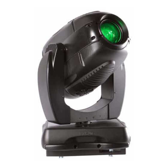
Related Manuals for Vari Lite VL3015


Summary of Contents for Vari Lite VL3015
- Page 2 This manual is for informational use only and is subject to change without notice. Philips Vari-Lite assumes no responsibility or liability for any claims resulting from errors or inaccuracies that may appear in this manual. Version as of: 14 November 2012 Part number: 02.9679.0010 0 VL3015 & VL3515 Spot Luminaires Service Manual ©2012, Vari-Lite, a Philips group company. All Rights Reserved.
- Page 3 OREWORD How To Obtain Warranty Service A copy of the Vari-Lite Limited Warranty was included in the shipping package for this VARI❋LITE product. To obtain warranty service, please contact customer service at 1-877-VARI-LITE (1-877-827-4548), +1-214-647-7880, or entertainment.service@philips.com and request a Return Material Authorization (RMA) for warranty service.
- Page 4 ❋ VARI LITE - VL3015 & VL3515 S UMINAIRES ERVICE ANUAL Compliance Notice This equipment has been tested and found to comply with the limits for a Class A digital device pursuant to Part 15 of FCC Rules. These limits are designed to provide reasonable protection against harmful interference when this equipment is operated in a commercial environment.
- Page 5 WARNING: INSTRUCTIONS FOR CONTINUED PROTECTION AGAINST FIRE 1. VARI❋LITE luminaires have been designed for use with specific lamp types. VL3015 & VL3515 Spot Luminaires require an Osram HMI 1200 W/S metal halide lamp. Installing another type of lamp may be hazardous.
- Page 6 ❋ VARI LITE - VL3015 & VL3515 S UMINAIRES ERVICE ANUAL WARNING: INSTRUCTIONS FOR CONTINUED PROTECTION AGAINST EXCESSIVE EXPOSURE TO UV RADIATION 1. Many VARI❋LITE luminaires use a lamp that produces UV radiation. DO NOT look directly at lamp. 2. It is hazardous to operate luminaires without lens or shield. Shields, lenses, or ultraviolet screens shall be changed if they have become visibly damaged to such an extent that their effectiveness is impaired.
- Page 7 OREWORD Sicherheitshinweise Es ist äußerst wichtig, ALLE Sicherheitsinformationen und -hinweise in diesem Handbuch und dem beiliegenden Informationsmaterial zu lesen, bevor Sie die hierin beschriebenen Produkte installieren bzw. bedienen. Halten Sie bei der Installation und dem Einsatz dieses Produkts alle Warnhinweise und Vorsichtsmaßnahmen ein.
- Page 8 ❋ VARI LITE - VL3015 & VL3515 S UMINAIRES ERVICE ANUAL WARNUNG: HINWEISE ZUM SCHUTZ GEGEN ÜBERHÖHTE UV-STRAHLUNG 1. Viele VARI❋LITE -Scheinwerfer verwenden die Lampentyp, der UV-Strahlen abgibt. SCHAUEN SIE NICHT direkt in die Lampe. 2. Es ist gefährlich, Leuchten ohne Linsen oder Blenden zu bedienen. Blenden, Linsen oder Ultraviolettschirme müssen ausgetauscht werden, sofern deren Schutzwirkung durch sichtbare...
- Page 9 OREWORD Notes de sécurité Avant de procéder à l’installation des produits décrits dans ce guide et de les mettre en marche, il est extrêmement important de lire TOUS les renseignements et TOUTES les directives de sécurité contenues dans ce guide ainsi que toute documentation jointe. Tenir compte de tous les avertissements et suivre toutes les précautions pendant l’installation et l’utilisation de cet appareil.
- Page 10 ❋ VARI LITE - VL3015 & VL3515 S UMINAIRES ERVICE ANUAL AVERTISSEMENT: DIRECTIVES POUR SE PROTÉGER CONTRE UNE EXPOSITION EXCESSIVE AUX RAYONS UV 1. Plusieurs luminaires VARI❋LITE utilisent une lampe qui produit des rayons UV. NE PAS fixer son regard sur la lampe.
- Page 11 OREWORD Aviso sobre Seguridad Es muy importante leer TODA la información e instrucciones sobre seguridad que se indica en este manual así como en los documentos adjuntos antes de instalar y operar los productos descritos. Se debe prestar atención a todos los avisos y advertencias durante la instalación y uso de este producto. Los símbolos de seguridad usados en este manual son los siguientes: CUIDADO, indica posibles daños al producto.
- Page 12 ❋ VARI LITE - VL3015 & VL3515 S UMINAIRES ERVICE ANUAL ADVERTENCIA: INSTRUCCIONES PARA PROTECCIÓN CONTINUA CONTRA LA EXPOSICIÓN EXCESIVA DE RADIACIÓN ULTRA VIOLETA 1. Muchas luminarias VARI❋LITE usan un tipo de lámpara que produce radiación UV. NO mire directamente a la lámpara.
- Page 13 OREWORD 02.96 79.001 0 0...
- Page 14 ❋ VARI LITE - VL3015 & VL3515 S UMINAIRES ERVICE ANUAL 0 2.9679 .0 010 0...
-
Page 15: Table Of Contents
VL3515 Spot Luminaire...................... 4 Technical Specifications ......................5 Components External Luminaire Components ....................6 VL3015 Spot Luminaire Head and Yoke Components............. 7 VL3515 Spot Luminaire Head and Yoke Components............. 8 Enclosure Components ......................9 Principles of Operation VL3015 Spot Luminaire Functional Block Diagram.............. 10 VL3515 Spot Luminaire Functional Block Diagram.............. - Page 16 Drawing Trees VL3015 Spot Luminaire ......................54 VL3515 Spot Luminaire ......................57 Top Assembly Included Items Kit, VL3015 Spot ................... 60 Included Items Kit, VL3515 Spot ................... 62 VL3015 Spot Luminaire ......................64 VL3515 Spot Luminaire ......................67 Generic Luminaire Assembly ....................70 Head Cover Assembly ......................
- Page 17 ABLE OF ONTENTS Fixed Color Wheel Assembly ....................97 Long Shaft Motor Assembly....................99 Rotating Gobo Wheel Assembly................... 100 Rotating Effects Wheel Assembly ..................101 Iris Sub-Assembly......................... 102 Color Sensor PCB #1 Mount Assembly ................104 Color Sensor PCB #2 Mount Assembly ................105 Gobo Wheel / Shutter Module Assembly ................
- Page 18 OT Switch 1 to OT Switch 2 Cable Assembly ..............185 Backcap Interlock to Thermal Switch 1 Cable Assembly ............ 186 Dual DC Fan, LVS to Yoke Cable Assembly ............... 187 Appendix A. Technical Bulletins VL3015 & VL3515 Spot Luminaires Technical Bulletins ........... 189 0 2.9679 .0 010 0...
-
Page 19: Introduction
About This Manual This manual provides descriptions, repair procedures, and illustrated parts breakdowns for all configurations of the VL3015 & VL3515 Spot Luminaires. The manual is intended for use by Vari- Lite personnel and Authorized VARI❋LITE Service Centers and technicians only. -
Page 20: Customer Service
❋ VARI LITE - VL3015 & VL3515 S UMINAIRES ERVICE ANUAL Customer Service Our Goal At Vari-Lite, we are committed to providing you the highest quality in customer service. Our comprehensive resources are available to help your business succeed and ensure you get the full benefit of being a Vari-Lite customer. -
Page 21: Chapter 1. Description
HAPTER Description This chapter contains descriptions of luminaire features and components. • Features • Components • Principles of Operation 02.96 79.001 0 0... -
Page 22: Features
ANUAL Features Standard Features All VL3015 & VL3515 Spot Luminaires have the following standard features: • Color System: A three-filter CYM cross-fading mechanism. A fixed color wheel with six interchangeable color filters and continuous wheel rotation for additional effects. It includes a variable CTO color temperature correction wheel. -
Page 23: Technical Specifications
PECIFICATIONS Technical Specifications For additional technical specifications and information, please refer to VL3015 & VL3515 Spot Luminaires User’s Manual (02.9679.0002) and the individual product specification sheets. These documents can be found in the product downloads section of the Vari-Lite web site at www.vari-... -
Page 24: Components
❋ VARI LITE - VL3015 & VL3515 S UMINAIRES ERVICE ANUAL Components External Luminaire Components The following illustration shows the external luminaire components and controls. Head Assembly Houses color, gobo, strobe, iris (or shutter*) and zoom lens mechanisms Backcap Assembly... -
Page 25: Vl3015 Spot Luminaire Head And Yoke Components
: VL3015 S OMPONENTS UMINAIRE EAD AND OMPONENTS VL3015 Spot Luminaire Head and Yoke Components The following illustration shows the major sub-assemblies which are located in the luminaire head and yoke assemblies. Head Cover (attached by tether) Head Fan Rotating Gobo Assembly... -
Page 26: Vl3515 Spot Luminaire Head And Yoke Components
❋ VARI LITE - VL3015 & VL3515 S UMINAIRES ERVICE ANUAL VL3515 Spot Luminaire Head and Yoke Components The following illustration shows the major sub-assemblies which are located in the luminaire head and yoke assemblies. Head Cover (attached by tether) -
Page 27: Enclosure Components
OMPONENTS NCLOSURE OMPONENTS Enclosure Components The following illustration shows the major sub-assemblies which are located in the luminaire enclosure assembly. (Yoke and head assemblies not shown for clarity.) Universal Arc Ballast Luminaire Handles Module 1200W / 1650W Pan Tube Assembly Fan Assembly Enclosure Top Covers 200W +24VDC /... -
Page 28: Principles Of Operation
❋ VARI LITE - VL3015 & VL3515 S UMINAIRES ERVICE ANUAL Principles of Operation VL3015 Spot Luminaire Functional Block Diagram Rotating Sensor Gobo 1 Rotating Sensor Gobo 2 Cyan Sensor Wheel Rotating Sensor Gobo Rotating Gobo 3 Index 1 Sensor... -
Page 29: Vl3515 Spot Luminaire Functional Block Diagram
: VL3515 S RINCIPLES OF PERATION UMINAIRE UNCTIONAL LOCK IAGRAM VL3515 Spot Luminaire Functional Block Diagram Fixed Sensor Gobo Shutter Cyan Sensor Motor 1A Wheel Shutter Shutter Motor 4B Motor 1B Rotating Sensor Gobo Yellow Sensor Wheel Shutter Shutter Shutter Motor 4A Assembly Motor 2A... - Page 30 ❋ VARI LITE - VL3015 & VL3515 S UMINAIRES ERVICE ANUAL Notes 02 .9 679.00 10 0...
-
Page 31: Chapter 2. Maintenance
HAPTER Maintenance This chapter contains test, service, and standard maintenance procedures. • Testing • Troubleshooting • Maintenance Procedures WARNING: All maintenance procedures are to be performed with power removed from the luminaire. Never remove cover or backcap while lamp is in oper- ation. -
Page 32: Testing
Luminaire User’s Manual (02.9679.0002). This manual is available on the Vari-Lite web site, in the product download section, at www.vari-lite.com. Calibration Sequence - VL3015 Spot Luminaire Note: This calibration sequence is only for the VL3015 spot luminaire only. For the VL3515 spot luminaire, refer to “Calibration Sequence - VL3515 Spot Luminaire” on page The following is an outline of the luminaire’s standard calibration sequence:... -
Page 33: Calibration Sequence - Vl3515 Spot Luminaire
EQUENCE UMINAIRE Calibration Sequence - VL3515 Spot Luminaire Note: This calibration sequence is only for the VL3515 spot luminaire only. For the VL3015 spot luminaire, refer to “Calibration Sequence - VL3015 Spot Luminaire” on page The following is an outline of the luminaire’s standard calibration sequence: Phase 1 •... -
Page 34: Partial Recalibration
❋ VARI LITE - VL3015 & VL3515 S UMINAIRES ERVICE ANUAL Note: Colors (CTO and CYM) will only auto recalibrate when the dimmer has been closed for 3 seconds. Partial Recalibration It is possible to recalibrate sections of the luminaire from a console. This allows greater flexibility and speed by only forcing a recalibration on specific mechanisms. - Page 35 (refer to the VL3015 & VL3515 Spot Luminaire User's Manual). On at full power will be one-half (1/2) PWM (which will meter at approximately 2vdc). On at Medium Power (1200W) will be no PWM signal (0vdc).
-
Page 36: Troubleshooting
Troubleshooting Error Messages - VL3015 Spot Luminaire Note: Table 2-1, “Error Messages - VL3015 Spot Luminaire,” on page 18 is only for the VL3015 spot luminaire only. For the VL3515 spot luminaire, refer to “Error Messages - VL3515 Spot Luminaire”... -
Page 37: Error Messages - Vl3515 Spot Luminaire
UMINAIRE Error Messages - VL3515 Spot Luminaire Note: Table 2-1, “Error Messages - VL3015 Spot Luminaire,” on page 18 is only for the VL3515 spot luminaire only. For the VL3015 spot luminaire, refer to “Error Messages - VL3015 Spot Luminaire”... -
Page 38: Troubleshooting Guide
Troubleshooting Guide If a problem is suspected, try recalibrating the luminaire to prompt an error message. Refer to “Error Messages - VL3015 Spot Luminaire” on page 18 “Error Messages - VL3515 Spot Luminaire” on page 19 (depending on which product you have) for more information. The chart below provides possible causes and remedies for each message. - Page 39 ROUBLESHOOTING ROUBLESHOOTING UIDE Table 2-3: Troubleshooting Guide (Continued) Message Symptom Description Possible Cause and Remedy Pan No Luminaire will not pan Pan Sensor Not Found EOT flag attached to large pulley is not engaging the Sens EOT sensor... - ensure flag is attached to the large pulley. - ensure that flag passes through the sensor at a depth sufficient to engage the sensor beam.
-
Page 40: Maintenance Procedures
❋ VARI LITE - VL3015 & VL3515 S UMINAIRES ERVICE ANUAL Maintenance Procedures WARNING: As with any repairs or maintenance to VARI❋LITE luminaires, service should only be performed by a trained and qualified service technician or at an Authorized Vari-Lite Service facility. -
Page 41: Align Lamp
Align Lamp The design of the VL3015 & VL3515 Spot Luminaire optical system allows for a flat or peaked field. A flat field is one where there is no detectable hot spot and a peaked field is one where the intensity of the beam is greater at the center of the beam than at the perimeter. -
Page 42: Reflector Change
ANUAL Reflector Change The VL3015 Spot and VL3515 Spot luminaires come with both a Peaked and Flat Field Reflector. Users can choose between either reflector as desired. Note: The unit, when shipped from the factory, has the Peaked Reflector installed in the unit’s hot box and the Flat Field Reflector stored in the luminaire head assembly underneath the bottom head cover. - Page 43 AINTENANCE ROCEDURES EFLECTOR HANGE Step 5. As shown in Figure 2-4, remove stored reflector by removing acorn nut and foam washer securing reflector in luminaire head assembly. Set reflector aside on a soft clean cloth. Reflector Assembly Storage Location Reflector Assembly Acorn Nut Foam Washer Figure 2-4: Reflector Removal (From Storage Location)
- Page 44 ❋ VARI LITE - VL3015 & VL3515 S UMINAIRES ERVICE ANUAL Step 8. Using a flat screwdriver, remove current reflector from hot box assembly as follows: a. Press tabs (one on each side) securing reflector assembly into hot box (as shown in Figure 2-6), inwards to release reflector assembly.
-
Page 45: Gobo Replacement - Gobo Wheels 1, 2, And 3
To remove and replace a gobo: Step 1. Remove power from luminaire. Step 2. Remove appropriate head cover by loosening four 1/4-turn screws: a. For VL3015 spot luminaires: 1) To access Wheel 1 and 3, remove bottom cover as shown in Figure 2-7. - Page 46 Clean with glass cleaner and soft cloth if required. Step 5. As shown in Figure 2-8, for Gobo Wheels 1, 2 and 3 (VL3015 spot) and Rotating Gobo Wheel (VL3515 spot): a. Remove current gobo by carefully pressing on edges of gobo carrier with fingers, pressing gobo toward front end of luminaire (toward lens), and out of wheel.
- Page 47 1, 2, AINTENANCE ROCEDURES EPLACEMENT HEELS d. Reinstall (close) gobo spring retaining clip. Ensure clips are positioned correctly and clear position sensor. e. Replace covers. IXED HEEL Gobo Assembly Carrier Spring Retaining Clip Slide gobo carrier (closed) into gobo slot Gobo Wheel 2 (note: gobo is keyed) Spring Retaining Clip...
-
Page 48: Color Filter Replacement
❋ VARI LITE - VL3015 & VL3515 S UMINAIRES ERVICE ANUAL Color Filter Replacement WARNING: Remove power from luminaire before performing maintenance. Filters may be HOT after operation. Allow to cool before replacing. To remove and replace a color filter: Step 1. -
Page 49: Ballast Assembly Replacement
AINTENANCE ROCEDURES ALLAST SSEMBLY EPLACEMENT Ballast Assembly Replacement Vari-Lite Part No: 69.9679.1216 To remove and replace ballast assembly: Step 1. Using console or internal menus, run lens as far to the rear as possible. Step 2. Remove power from luminaire. WARNING: You must remove all power from luminaire before performing maintenance. - Page 50 ❋ VARI LITE - VL3015 & VL3515 S UMINAIRES ERVICE ANUAL Step 9. At enclosure bottom, remove two 6-32 x 3/8" PPB screws, APS side bracket and front cover from ballast side. Step 10. At bottom of enclosure, disconnect exhaust fan cable.
-
Page 51: Color/Dimmer/Strobe Assembly Replacement
AINTENANCE ROCEDURES OLOR IMMER TROBE SSEMBLY EPLACEMENT Color/Dimmer/Strobe Assembly Replacement Vari-Lite Part No: 21.9679.0402 To remove and replace color/dimmer/strobe assembly: Step 1. Remove power from luminaire. WARNING: You must remove all power from luminaire before performing maintenance. Fixture may be very HOT after operation. Allow it to cool completely before performing any maintenance. Step 2. -
Page 52: Main Control Board (Mcb) Replacement
Remove two 6-32 x 3/8" PPZ screws and remove daughter board. Step 4. At MCB: a. On VL3015 luminaires: Remove two 6-32 x 3/4" PPZ screws and gently tilt MCB away from yoke assembly. b. On VL3515 luminaires: remove to 6-32 x 1/4" standoffs and gently tilt MCB away from yoke assembly Step 5. -
Page 53: Ignitor Board Replacement
AINTENANCE ROCEDURES GNITOR OARD EPLACEMENT Ignitor Board Replacement Vari-Lite Part No: 24.9661.3126 To remove and replace ignitor board assembly: Step 1. Remove power from luminaire. WARNING: You must remove all power from luminaire before performing maintenance. Fixture may be very HOT after operation. Allow it to cool completely before performing any maintenance. Step 2. -
Page 54: Pan Motor Assembly/Pan Belt Replacement
❋ VARI LITE - VL3015 & VL3515 S UMINAIRES ERVICE ANUAL Pan Motor Assembly/Pan Belt Replacement Vari-Lite Part No: 21.9678.8864 (Pan Motor) Vari-Lite Part No: 54.2055.0001 (Pan Belt) To remove and replace pan motor assembly / pan belt: Step 1. Using console or internal menus, run lens as far to the rear as possible. - Page 55 AINTENANCE ROCEDURES OTOR SSEMBLY EPLACEMENT WARNING: You must remove all power from luminaire before performing maintenance. Fixture may be very HOT after operation. Allow it to cool completely before performing any maintenance. Step 3. At each top enclosure cover, remove two 6-32x1/4" PPB screws and remove cover. Step 4.
-
Page 56: Pan Encoder Pcb Replacement
❋ VARI LITE - VL3015 & VL3515 S UMINAIRES ERVICE ANUAL Pan Encoder PCB Replacement Vari-Lite Part No: 24.9678.5000 To remove and replace pan encoder PCB: Step 1. Using console or internal menus, run lens as far to the rear as possible. -
Page 57: Pan Eot Sensor Replacement
EOT S AINTENANCE ROCEDURES ENSOR EPLACEMENT Pan EOT Sensor Replacement Vari-Lite Part No: 23.9678.0687 To remove and replace pan EOT sensor: Step 1. Using console or internal menus, run lens as far to the rear as possible. Step 2. Remove power from luminaire. WARNING: You must remove all power from luminaire before performing maintenance. -
Page 58: Power Supply (Lvs) Replacement
❋ VARI LITE - VL3015 & VL3515 S UMINAIRES ERVICE ANUAL Power Supply (LVS) Replacement Vari-Lite Part No: 69.3176.0201 To remove and replace LVS: Step 1. Remove power from luminaire. WARNING: You must remove all power from luminaire before performing maintenance. Fixture may be very HOT after operation. -
Page 59: Gobo/Iris Assembly Replacement
ROCEDURES SSEMBLY EPLACEMENT Gobo/Iris Assembly Replacement Vari-Lite Part No: 21.9679.0200 (VL3015 Spot) To remove and replace gobo/iris assembly: Step 1. Run Edge to full forward position (DMX 255). Step 2. Remove power from luminaire. WARNING: You must remove all power from luminaire before performing maintenance. Fixture may be very HOT after operation. -
Page 60: Gobo/Shutter Assembly Replacement
❋ VARI LITE - VL3015 & VL3515 S UMINAIRES ERVICE ANUAL Gobo/Shutter Assembly Replacement Vari-Lite Part No: 21.9679.1200 (VL3515 Spot) To remove and replace gobo/shutter assembly: Step 1. Run Edge to full forward position (DMX 255). Step 2. Remove power from luminaire. -
Page 61: Spot Optic Assembly Replacement
Step 3. Disconnect wiring for transfer fan and aperture fan wiring, and color/gobo fans as well as head cable from zoom interconnect PCB. Step 4. Cut case tie wrap holding zoom harness to optics assembly Step 5. Remove appropriate assembly for fixture: a. For VL3015 fixtures: remove Gobo/Iris Assembly. (See “Gobo/Iris Assembly Replacement” on page 41.) b. - Page 62 ❋ VARI LITE - VL3015 & VL3515 S UMINAIRES ERVICE ANUAL Step 9. Finish by performing steps, in“To remove spot optics assembly:” on page 43, in reverse order. Note: Test edge function. If binding, lead screw is not straight. Loosen nut and retighten. To prevent binding, thread edge screw all the way into linear actuator motor before re-installing.
-
Page 63: Tilt Motor Assembly And Tilt Belt Replacement
AINTENANCE ROCEDURES OTOR SSEMBLY AND EPLACEMENT Tilt Motor Assembly and Tilt Belt Replacement Vari-Lite Part No: 21.9678.8765 (Tilt Motor) Vari-Lite Part No: 54.2055.0001 (Tilt Belt) To remove and replace tilt motor: Step 1. Remove power from luminaire. WARNING: You must remove all power from luminaire before performing maintenance. Fixture may be very HOT after operation. - Page 64 ❋ VARI LITE - VL3015 & VL3515 S UMINAIRES ERVICE ANUAL Step 7. Remove belt. Step 8. Replace by performing previous steps in reverse order. WARNING: Make sure wiring is not pinched during installation. When tightening four 10-32 x 1/2"...
-
Page 65: Tilt Encoder Pcb Replacement
PCB R AINTENANCE ROCEDURES NCODER EPLACEMENT Tilt Encoder PCB Replacement Vari-Lite Part No: 24.9661.5000 To remove and replace tilt encoder PCB: Step 1. Remove power from luminaire. WARNING: You must remove all power from luminaire before performing maintenance. Fixture may be very HOT after operation. Allow it to cool completely before performing any maintenance. Step 2. -
Page 66: Tilt Eot Sensor Replacement
❋ VARI LITE - VL3015 & VL3515 S UMINAIRES ERVICE ANUAL Tilt EOT Sensor Replacement Vari-Lite Part No: 23.9661.1253 To remove and replace tilt EOT sensor: Step 1. Remove power from luminaire. WARNING: You must remove all power from luminaire before performing maintenance. Fixture may be very HOT after operation. -
Page 67: Gobo Timing Adjustments
Step 5. To time Gobo Wheel 3 (VL3015 spot only), first align planet gear timing mark with hole in wheel. Loosen index belt just enough to slip teeth and rotate index pulley to center slot in optical sensor as shown. - Page 68 ❋ VARI LITE - VL3015 & VL3515 S UMINAIRES ERVICE ANUAL Gobo Timing Adjustments (continued) Position index pulley so large flange is Insert a 3" long #4 or M3 screw (or 0.125" diameter centered in optical sensor pin) completely through aligned holes in wheels and both bulkheads as shown.
-
Page 69: Gobo Gear Planet Alignment
AINTENANCE ROCEDURES LANET LIGNMENT Gobo Gear Planet Alignment Each gear of the gobo wheel assembly must be aligned so that the gobos will index correctly. Use the following procedure to re-align the gears in the event the gobo wheel is disassembled. To re-align gobo gears: Step 1. -
Page 70: Gobo Gear Planet Alignment (Continued)
❋ VARI LITE - VL3015 & VL3515 S UMINAIRES ERVICE ANUAL Gobo Gear Planet Alignment (continued) 1) Start with center gear timing 2) Rotate center gear clockwise until timing mark facing Position 1 (open). mark is directly across from Position 6. -
Page 71: Chapter 3. Illustrated Parts Breakdown
HAPTER Illustrated Parts Breakdown This chapter contains illustrated parts breakdowns for all VL3015 & VL3515 Spot Luminaire assemblies. • Drawing Trees • Top Assembly • Head Assembly • Yoke Assembly • Enclosure Assembly • Cable Assemblies 02.96 79.001 0 0... -
Page 72: Drawing Trees
22.9678.1105 Rev C Assembly Assembly 22.9678.1115 Rev E 25.9686.0013 Rev A Backcap Interlock to Thermal Switch 1 Cable Assembly Continued Next Page 25.9686.0014 Rev 0 Figure 3-1: VL3015 Spot Luminaire Subassembly Drawing Tree Part 1 02 .9 679.00 10 0... - Page 73 Color Sensor PCB #2 Mount 25.9679.0005 Rev 0 Assembly 22.9678.0489 Rev B Iris Fan Cable Assembly 25.9679.0007 Rev A Color Interconnect Cable Assembly 25.9678.1419 Rev 0 Figure 3-2: VL3015 Spot Luminaire Subassembly Drawing Tree Part 2 02.96 79.001 0 0...
- Page 74 Assembly Pan/Tilt Control Cable Assembly 25.9678.0829 Rev A 25.9678.0818 Rev C LVS Chassis Ground Cable Assembly 25.9678.1716 Rev A Display Cable Assembly 25.9678.1825 Rev A Figure 3-3: VL3015 Spot Luminaire Subassembly Drawing Tree Part 3 02 .9 679.00 10 0...
-
Page 75: Vl3515 Spot Luminaire
: VL3515 S RAWING REES UMINAIRE VL3515 Spot Luminaire VL3515 Spot Luminaire 21.9679.0002 Rev. E Shutter Transfer Fan Assembly Generic Luminaire Assembly 21.9678.1263 Rev 0 21.9679.0010 Rev. A Quick Change Luned Reflector Assembly 21.9679.0151 Rev A Quick Change Smooth Reflector Head Structure Assembly Assembly 21.9679.0600 Rev. - Page 76 ❋ VARI LITE - VL3015 & VL3515 S UMINAIRES ERVICE ANUAL VL3515 Spot Luminaire (continued) Continued From Previous Page Continued From Previous Page VL3515 Spot Luminaire 21.9679.0002 Rev. E Generic Luminaire Assembly Gobo Wheel / Shutter Module 21.9679.0010 Rev. A Assembly 21.9679.1200 Rev.
- Page 77 : VL3515 S RAWING REES UMINAIRE VL3515 Spot Luminaire (continued) Continued From Previous Page Upper Enclosure Assembly 21.9679.0800 Rev. E Pan Pulley Assembly 21.9678.0807 Rev E EMI Filter to LVS Cable Assembly Stabilizer Assembly 25.9679.0002 Rev 0 21.9678.0767 Rev 0 Ballast Power Cable Assembly 25.9679.0003 Rev 0 Pan Tube Assembly...
-
Page 78: Top Assembly
❋ VARI LITE - VL3015 & VL3515 S UMINAIRES ERVICE ANUAL Top Assembly Included Items Kit, VL3015 Spot 28.9679.0001 Rev. A Refer to Figure 3-7. Item Qty. Description 02.8001.0001 PRODUCT SUPPORT SHEET, VARI-LITE CUSTOMER SERVICE 02.8052.0001 CARD, LIMITED WARRANTY 02.8406.0001 TAG, LAMP NOTICE 02.8700.0001... - Page 79 Triangle Breakup Circle of Ovals Figure 3-7: Included Items Kit, VL3015 Spot Note: * = Do not handle lamp with bare hands. When handling, it is best to wear clean cotton gloves in order to keep the lamp’s glass as dirt and grease free as possible.
-
Page 80: Included Items Kit, Vl3515 Spot
❋ VARI LITE - VL3015 & VL3515 S UMINAIRES ERVICE ANUAL Included Items Kit, VL3515 Spot 28.9679.0002 Rev. B Refer to Figure 3-8. Item Qty. Description 02.8001.0001 PRODUCT SUPPORT SHEET, VARI-LITE CUSTOMER SERVICE 02.8052.0001 CARD, LIMITED WARRANTY 02.8406.0001 TAG, LAMP NOTICE 02.8700.0001... - Page 81 Pebbles Circle of Ovals Figure 3-8: Included Items Kit, VL3015 Spot Note: * = Do not handle lamp with bare hands. When handling, it is best to wear clean cotton gloves in order to keep the lamp’s glass as dirt and grease free as possible.
-
Page 82: Vl3015 Spot Luminaire
CABLE ASSY, RELAY TO GOBO INTERLOCK SWITCH (not shown) 25.9678.0715 CABLE ASSY, HEAD CONTROLLER (not shown) 25.9679.0005 CABLE ASSY, COLOR/GOBO DUAL FAN (not shown) 25.9679.0007 CABLE ASSY, VL3015 IRIS FAN ADAPTER (not shown) 28.9679.0001 INCLUDED ITEM KIT, VL3015 SPOT (not shown) 02 .9 679.00 10 0... - Page 83 : VL3015 S SSEMBLY UMINAIRE Item Qty. Description 53.2001.0003 NUT, 10-32 HEX SS NYLON INSERT 53.2202.0008 NUT, 8-32 HEX SS NYLON INSERT 53.6523.0013 SCREW, 6-32 X 3/8" PTB 53.6558.0001 SCREW. 6-32 X 3/8" PPZ 53.6558.0007 SCREW, 6-32 X 1/4" PPZ SEMS 53.6558.0009...
- Page 84 ❋ VARI LITE - VL3015 & VL3515 S UMINAIRES ERVICE ANUAL VL3015 Spot Luminaire (continued) (x2) (x2) (x2) (x2) (x4) (x2) (x4) (x4) (x2) (x2) 21.9679.0155 Ref. (x2) (x4) (x2) (x2) (x8) (x4) (x2) Figure 3-9: VL3015 Spot Luminaire 02 .9 679.00 10 0...
-
Page 85: Vl3515 Spot Luminaire
COVER, YOKE, THERMOFORM 21.9679.0151 REFLECTOR ASSY, LUNED, QUICK CHANGE 21.9678.1246 ASSY, CABLE INTERCONNECT, SHUTTER 21.9678.1263 TRANSFER FAN ASSY, SHUTTER 21.9679.0010 ASSY, GENERIC LUMINAIRE, VL3015 21.9679.0155 REFLECTOR ASSY, SMOOTH, QUICK CHANGE (not shown) 21.9679.0402 ASSY, COLOR MODULE 21.9679.0611 ASSY, HEAD COVER 21.9679.0625 FAN ASSY, COLOR/GOBO ACCESS, VL3515 21.9679.1200... - Page 86 ❋ VARI LITE - VL3015 & VL3515 S UMINAIRES ERVICE ANUAL Item Qty. Description 53.2001.0003 NUT, 10-32 HEX SS NYLON INSERT 53.2202.0008 NUT, 8-32 HEX SS NYLON INSERT 53.6523.0013 SCREW, 6-32 X 3/8" PTB 53.6558.0001 SCREW. 6-32 X 3/8" PPZ 53.6558.0007...
- Page 87 : VL3515 S SSEMBLY UMINAIRE VL3515 Spot Luminaire (continued) (x2) (x2) (x2) (x2) (x4) (x2) (x4) (x4) (x4) (x2) (x2) 21.9679.0155 Ref. (x2) (x4) (x2) (x2) (x8) (x4) (x2), (x2) Figure 3-10: VL3515 Spot Luminaire 02.96 79.001 0 0...
-
Page 88: Generic Luminaire Assembly
❋ VARI LITE - VL3015 & VL3515 S UMINAIRES ERVICE ANUAL Generic Luminaire Assembly 21.9679.0010 Rev. A Refer to Figure 3-11 Item Qty. Description 21.9678.0700 ASSY, YOKE 21.9678.0707 ASSY, TILT PULLEY - 10.9678.0750 TIMING PULLEY, 150 TOOTH - 10.9678.0754 FLAG, CENTER OF TRAVEL, TILT - 53.6530.0006... - Page 89 SSEMBLY ENERIC UMINAIRE SSEMBLY Generic Luminaire Assembly (continued) (x3) Detail A Detail B (x2) (x2) (x2) (x4) (x2) Detail C (x5), (x5) (x4) Note position of safety tether. Detail A Detail B Detail C (x4) (x4) (x3) Figure 3-11: Generic Luminaire Assembly 02.96 79.001 0 0...
-
Page 90: Head Cover Assembly
❋ VARI LITE - VL3015 & VL3515 S UMINAIRES ERVICE ANUAL Head Cover Assembly 21.9679.0611 Rev. A Refer to Figure 3-12 Item Qty. Description 10.9678.0612 HEAD COVER FOAM BAFFLE 10.9678.0649 EJECTOR SPRING, BLACK OXIDE 10.9678.0674 BRACKET, COVER TETHER 10.9686.1696 FOAM FRAME, HEAD COVER 12.9679.0610... -
Page 91: Spot Transfer Fan Assembly
SSEMBLY RANSFER SSEMBLY Spot Transfer Fan Assembly 21.9678.0678.01 Rev E Refer to Figure 3-13 Item Qty. Description 10.9678.0679 TRANSFER FAN TRAY 23.9678.0695 FAN ASSY, TRANSFER 53.6571.0003 SCREW, 6-32 X 1-1/2"LG PPB 55.6543.0001 2.12 GROMMET STRIP, SERRATED POLYETHYLENE 55.6769.0004 TWIST-LOK 0.55" ID NOM WHT 85 C MAX FLAME RET (x3) Spot Only Figure 3-13: Spot Transfer Fan Assembly... -
Page 92: Shutter Transfer Fan Assembly
❋ VARI LITE - VL3015 & VL3515 S UMINAIRES ERVICE ANUAL Shutter Transfer Fan Assembly 21.9678.1263 Rev 0 Refer to Figure 3-14 Item Qty. Description 10.9678.0679 TRANSFER FAN TRAY 22.9678.1280 SHIELD ASSY, SHUTTER ROTATE HARNESS 23.9678.0695 ASSY, TRANSFER FAN 53.6558.0001 SCREW, 6-32 X.375"... -
Page 93: Color/Gobo Access Fan Assembly
SSEMBLY OLOR CCESS SSEMBLY Color/Gobo Access Fan Assembly 21.9679.0620 Rev C (VL3015 Spot Only) Refer to Figure 3-15 Item Qty. Description 55.7016.0001 FAN GUARD, 80MM, NICKEL PLATED 10.9678.1649 FAN SHIELD, LAMP COOLING. 10.9679.0665 FAN TRAY, COLOR/GOBO COOLING, VL3015 23.9679.0016 FAN, TUBAXIAL, 80MM 24VDC, LAMP COOLING, LONG LIFE 53.6571.0002... -
Page 94: Color/Gobo Access Fan Assembly
❋ VARI LITE - VL3015 & VL3515 S UMINAIRES ERVICE ANUAL Color/Gobo Access Fan Assembly 21.9679.0625 Rev C (VL3515 Spot Only) Refer to Figure 3-16 Item Qty. Description 55.7016.0001 FAN GUARD, 80MM, NICKEL PLATED 10.9678.1649 FAN SHIELD, LAMP COOLING, DC 10.9679.0667... -
Page 95: Quick Change Luned Reflector Assembly
SSEMBLY UICK HANGE UNED EFLECTOR SSEMBLY Quick Change Luned Reflector Assembly 21.9679.0151 Rev A Refer to Figure 3-17 Item Qty. Description 10.9678.2647 CLAMP, PRIMARY REFLECTOR, SST 10.9679.0642 REFLECTOR MOUNT, QUICK CHANGE 12.9678.8151 REFLECTOR, HTG, VL3000 SERIES SPOT, LUNED 53.6582.0001 SCREW, 6-32 X 3/4" PFZ 55.6568.0077 SPRING, CPRSN, 0.30"... -
Page 96: Quick Change Smooth Reflector Assembly
❋ VARI LITE - VL3015 & VL3515 S UMINAIRES ERVICE ANUAL Quick Change Smooth Reflector Assembly 21.9679.0155 Rev C Refer to Figure 3-18 Item Qty. Description 10.9678.2647 CLAMP, PRIMARY REFLECTOR, SST 10.9679.0642 REFLECTOR MOUNT, QUICK CHANGE 12.9678.8155 REFLECTOR, HTG, VL3000 SERIES WASH, SMOOTH, CERAMIC 53.6582.0001... -
Page 97: Head Assembly
SSEMBLY TRUCTURE SSEMBLY Head Assembly Head Structure Assembly 21.9679.0600 Rev. D Refer to Figure 4-19 Item Qty. Description 10.9678.8620 FRONT CASTING 10.9679.0124 FAN SUPPORT CROSSMEMBER, FRONT 12.9678.8623 RIGHT SIDE RAIL, MACHINED 12.9678.8625 LEFT SIDE RAIL, MACHINED 21.9679.0615 ASSY, BACKEND 53.6515.0001 SCREW, 10-32 X 3/4"... - Page 98 ❋ VARI LITE - VL3015 & VL3515 S UMINAIRES ERVICE ANUAL Head Structure Assembly (continued) (x6) (x3) Figure 4-19: Head Structure Assembly 02 .9 679.00 10 0...
-
Page 99: Backend Assembly
SSEMBLY ACKEND SSEMBLY Backend Assembly 21.9679.0615 Rev E Refer to Figure 4-20 Item Qty. Description 10.9678.0637 CLIP, RETRO-REFLECTOR 10.9678.0653 LIGHT BAFFLE, EXHAUST 10.9678.1649 FAN SHIELD, LAMP COOLING, DC 10.9679.0615 SILICONE TUBING, HOT BOX SEAL 10.9679.0638 AIR DIVERTER, STROBE MOTOR 10.9679.0671 BULKHEAD, SEPARATION 10.9679.0680 REFLECTOR ACCESS, AIR DIVERTER... - Page 100 ❋ VARI LITE - VL3015 & VL3515 S UMINAIRES ERVICE ANUAL Item Qty. Description 55.6538.0004 WASHER, TEFLON, 0.312" X 0.750" X 0.125" 55.6541.0008 GROMMET, 1/2" ID 7/8" OD 11/32" THK 55.6677.0042 WASHER, TEFLON, 0.50" OD 55.6706.0001 GROMMET, 9/32" ID 9/16" OD 1/4" THK SI 74.1099.0001...
- Page 101 SSEMBLY ACKEND SSEMBLY Backend Assembly (continued) (x4), (x4) (x2) (x2) (x2) (x2) (x8) (x2) (x4) (x2) (X4) (x4) (x4) (x18) (x2) (x4) (x8) (x6) (x2) (x2) (x6) *Note, when installing item 4, apply a thin bead of Copper RTV the entire length of the slit. Secure to bulkhead (item 6) using item 9 (x2).
-
Page 102: 80Mm Dc Fan Assembly
❋ VARI LITE - VL3015 & VL3515 S UMINAIRES ERVICE ANUAL 80mm DC Fan Assembly 21.9679.0616 (Rev. A) Refer to Figure 4-21 Item Qty. Description 40.7113.0015 FAN, TUBEAXIAL 80MM 24VDC, HIGH 53.2002.0001 NUT, 6-32 KEPS ZINC 53.6558.0001 SCREW, 6-32 X 3/8" LG PPZ 55.7016.0001... -
Page 103: Uv Filter Bulkhead Assembly
: UV F SSEMBLY ILTER ULKHEAD SSEMBLY UV Filter Bulkhead Assembly 22.9678.0617 Rev D Refer to Figure 4-22 Item Qty. Description 10.9678.0634 UV FILTER BULKHEAD 10.9678.0648 CLIP, UV GLASS 41.9678.1160 UV/IR FILTER, 3.00" X 3.00" 53.6530.0002 RIVET, 1/8 OD POP,.063-.125 GRIP, ALUM *Note: Install glass (item 3) with marks indicating IR coating side of filter facing (x4) -
Page 104: Hot Box (Quick Change) Assembly
❋ VARI LITE - VL3015 & VL3515 S UMINAIRES ERVICE ANUAL Hot Box (Quick Change) Assembly 21.9679.0640 Rev. C Refer to Figure 4-23 Item Qty. Description 10.9678.0043.04 LABEL PLATE, VL3500 WASH BACKCAP, BLACK 10.9678.0643 LAMP ADJUST STOP 10.9678.0645 KNOB, LAMP ADJUST, MOLDED 10.9678.0646... - Page 105 SSEMBLY UICK HANGE SSEMBLY Hot Box (Quick Change) Assembly (continued) (x2) (x3) (x4) (x8) (x4) (x3) (x3) Figure 4-23: Hot Box (Quick Change) Assembly 02.96 79.001 0 0...
-
Page 106: Dual Fan Duct Assembly
❋ VARI LITE - VL3015 & VL3515 S UMINAIRES ERVICE ANUAL Dual Fan Duct Assembly 22.9686.0674 Rev B Refer to Figure 4-24 Item Qty. Description 10.9686.0673 TURNING VANE, FAN DUCT 10.9686.1672 DUAL FAN DUCT 25.9678.0015 CABLE ASSY, OT SWITCH TO GROUND 25.9686.0013... -
Page 107: Gobo Module Assembly
SSEMBLY ODULE SSEMBLY Gobo Module Assembly 21.9679.0200 Rev. C (VL3015 Only) Refer to Figure 4-25 Item Qty. Description 10.9678.0215 BULKHEAD, GOBO MODULE, FRONT 10.9678.0216 BULKHEAD, GOBO MODULE, REAR 10.9678.0225 SHAFT, GOBO WHEEL 10.9678.0231 MOTOR PULLEY W/ FLANGES 10.9678.0232 PULLEY, GOBO DRIVE 10.9678.0244... - Page 108 ❋ VARI LITE - VL3015 & VL3515 S UMINAIRES ERVICE ANUAL Item Qty. Description 55.2150.0003 STANDOFF, 1/4" HEX 6-32 1.125" L 55.2178.0001 CABLE ANCHOR MOUNT, #8 SCREW MOUNTING 55.6506.0025 SPACER, 3/8" RND 1/8" LG 0.257" L 55.6506.0026 SPACER, 3/8" RND 31/32" LG 0.257" L 55.6506.0030...
- Page 109 SSEMBLY ODULE SSEMBLY Gobo Module Assembly (continued) (x16) (x4) (x2) (x6) (x4) (x2) (x2) (x2) (x2) (x4) (x2) (x12) (x8) (x3) (x4) (x2) (x3) (x4) (x3) (x3) (x4) (x4) (x8) (x3) (x3) Figure 4-25: Gobo Module Assembly 02.96 79.001 0 0...
-
Page 110: Color Module Assembly
❋ VARI LITE - VL3015 & VL3515 S UMINAIRES ERVICE ANUAL Color Module Assembly 21.9679.0402 Rev. E Refer to Figure 4-25 Item Qty. Description 10.9678.0456 SHAFT, COLOR WHEEL 10.9678.0457.02 SPACER, COLOR WHEEL, L 0.190 10.9678.0457.03 SPACER, COLOR WHEEL, L 0.123 10.9678.0457.04... - Page 111 SSEMBLY OLOR ODULE SSEMBLY Item Qty. Description 53.6597.0001 SCREW, 4-40 X 3/16" PPZ 53.6608.0003 SCREW, 6-32 X 3/16" LG PPZ 54.2059.0001 BELT, TIMING, MXL PITCH 150 TOOTH 54.2060.0001 BELT, TIMING, MXL PITCH 165 TOOTH 54.9679.0002 BELT, TIMING, MXL, 155 GRV, 0.188" W, SIL/KEV 55.2132.0011 STANDOFF, 1/4"...
- Page 112 ❋ VARI LITE - VL3015 & VL3515 S UMINAIRES ERVICE ANUAL Color Module Assembly (continued) See Detail A (x4) (x6) (x12) See Detail B Yellow Magenta Dimmer Cyan (x11) (x4) (x12) (x7) (x3) (x4) (x2) (x5) (x5) (x12) Detail B...
-
Page 113: Dimmer Wheel (Notched) Assembly
SSEMBLY IMMER HEEL OTCHED SSEMBLY Dimmer Wheel (Notched) Assembly 22.9678.0435.02 Rev B Refer to Figure 4-27 Item Qty. Description 55.2256.0001 MAGNET, 2:17 SMCO 2MM X 2MM Dichroic Coated Side Copper RTV Bead Dimmer Wheel Magnet Gluing Magnet to Dimmer Wheel Assembly Step 1. -
Page 114: Motor/Adapter Plate Assembly
❋ VARI LITE - VL3015 & VL3515 S UMINAIRES ERVICE ANUAL Motor/Adapter Plate Assembly 21.9678.0331 Rev 0 Refer to Figure 4-28 Item Qty. Description 10.9678.0330 PLATE, MOTOR ADAPTER 44.5031.0001 MOTOR, STEPPER 42MM X 40MM,10 53.6513.0002 SCREW, 3MM X 5MM LG PFZ METR (x4) Note orientation of adapter plate in relation to the motor. -
Page 115: Fixed Color Wheel Assembly
SSEMBLY IXED OLOR HEEL SSEMBLY Fixed Color Wheel Assembly 21.9678.0334 Rev D Refer to Figure 4-29 Item Qty. Description 10.9678.0322 SPIN SHAFT, COLOR WHEEL 10.9678.0332 SLIDING RETAINER 10.9678.0333 RETAINER CLIP 22.9678.1336 FAB ASSY, FIXED WHEEL/CLIP 41.9678.0305.01 COLOR FILTER, DEEP RED VL3000 41.9678.0305.02 COLOR FILTER, KELLY GREEN VL3000 41.9678.0305.03... - Page 116 ❋ VARI LITE - VL3015 & VL3515 S UMINAIRES ERVICE ANUAL Fixed Color Wheel Assembly (continued) (x6) (x6) (x6) (x6) (x3) POS 2 ORANGE POS 3 POS 1 KELLY CONGO GREEN BLUE POS 4 DARK OPEN FUCHSIA POS 6 POS 5...
-
Page 117: Long Shaft Motor Assembly
SSEMBLY HAFT OTOR SSEMBLY Long Shaft Motor Assembly 21.9678.0243 Rev 0 Refer to Figure 4-30 Item Qty. Description 10.9678.0330 PLATE, MOTOR ADAPTER 44.9678.0249 MOTOR, STEPPER 42MM X 34MM 60MM SHAFT 53.6513.0002 SCREW, 3MM X 5MM LG PFZ METRIC (x4) Note orientation of adapter plate in relation to the motor. Figure 4-30: Long Shaft Motor Assembly 02.96 79.001 0 0... -
Page 118: Rotating Gobo Wheel Assembly
❋ VARI LITE - VL3015 & VL3515 S UMINAIRES ERVICE ANUAL Rotating Gobo Wheel Assembly 21.9679.0210 Rev B Refer to Figure 4-31 Item Qty. Description 10.9663.1211 SPACER, TEFLON, GOBO GEAR 10.9663.1240 BEARING, GOBO WHEEL BORE 10.9678.0220 PLATE, ROTATING GOBO WHEEL 10.9678.0224... -
Page 119: Rotating Effects Wheel Assembly
SSEMBLY OTATING FFECTS HEEL SSEMBLY Rotating Effects Wheel Assembly 21.9698.0211 Rev A Refer to Figure 4-31 Item Qty. Description 10.9663.1211 SPACER, TEFLON, GOBO GEAR 10.9663.1240 BEARING, GOBO WHEEL BORE 10.9678.0221 PLATE, ROTATING EFFECTS WHEEL 10.9678.0224 RETAINING RING, PLANET 10.9678.0250 MAGNET TAPE 22.9678.0230 ASSY, PLANET GEAR 22.9698.0232... -
Page 120: Iris Sub-Assembly
❋ VARI LITE - VL3015 & VL3515 S UMINAIRES ERVICE ANUAL Iris Sub-Assembly 21.9679.0270 Rev B Refer to Figure 4-33 Item Qty. Description 10.9678.0273 MOTOR MOUNT, IRIS 10.9678.0276 CRANK,. IRIS 10.9678.0279 DIVERTER, GOBO AIR 10.9678.0280 ADJUSTABLE IRIS STOP 10.9679.0272 BULKHEAD, IRIS 10.9679.0278... - Page 121 SSEMBLY SSEMBLY Iris Sub-Assembly (continued) See Detail A (x2) (x3) (x3) (x4) (x4) Detail A (x2) (x2) Screw links (7b) into stud (7a) as far as possible keeping sides flat and in alignment. Use Loctite 242 (one drop, each link) during assembly Figure 4-33: Iris Sub-Assembly 02.96 79.001 0 0...
-
Page 122: Color Sensor Pcb #1 Mount Assembly
❋ VARI LITE - VL3015 & VL3515 S UMINAIRES ERVICE ANUAL Color Sensor PCB #1 Mount Assembly 22.9678.0481 Rev B Refer to Figure 4-34 Item Qty. Description 10.9678.0482 PCB MOUNT, COLOR SENSOR #1 24.9678.3480 PCB ASSY, COLOR SENSOR #1 53.6558.0001 SCREW, 6-32 X 3/8"... -
Page 123: Color Sensor Pcb #2 Mount Assembly
PCB #2 M SSEMBLY OLOR ENSOR OUNT SSEMBLY Color Sensor PCB #2 Mount Assembly 22.9678.0489 Rev B Refer to Figure 4-35 Item Qty. Description 10.9678.0452 PCB MOUNT, COLOR SENSOR #2 24.9678.3454 PCB ASSY, COLOR SENSOR #2 53.6558.0007 SCREW, 6-32 X 1/4" SEMS (x2) Figure 4-35: Color Sense PCB #2 Mount Assembly 02.96 79.001 0 0... -
Page 124: Gobo Wheel / Shutter Module Assembly
❋ VARI LITE - VL3015 & VL3515 S UMINAIRES ERVICE ANUAL Gobo Wheel / Shutter Module Assembly 21.9679.1200 Rev. B (VL3515 Spot Only) Refer to Figure 4-36 Item Qty. Description 10.9678.0128 PULLEY, ZOOM MOTOR 10.9678.0231 PULLEY, MOTOR, GOBO WHEEL DRIVE 10.9678.0232... - Page 125 SSEMBLY HEEL HUTTER ODULE SSEMBLY Item Qty. Description 55.6520.0001 WASHER, WAVE SPRING, 0.265" ID, 0.367" OD, 0.006" THK (x6) (x2) (x4) (x2) (x4) (x4) (x4) (x4) (x2) (x2) (x2), (x4) (x6) (x3) (x6) (x6) (x2) (x2) (x8) Figure 4-36: Shutter Assembly 02.96 79.001 0 0...
-
Page 126: Shutter Assembly
❋ VARI LITE - VL3015 & VL3515 S UMINAIRES ERVICE ANUAL Shutter Assembly 21.9678.1510 Rev J Refer to Figure 4-36 Item Qty. Description 10.9678.1526 PIVOT, SHUTTER BLADE, SHORT 10.9678.1527 PIVOT, SHUTTER BLADE, LONG 10.9678.1528 CAM STOP 10.9678.1529 CABLE CLAMP, SHUTTER 10.9678.1532... - Page 127 SSEMBLY HUTTER SSEMBLY Shutter Assembly (continued) 4, 28 (x2) (x4) (x6) (x8) (x4) (x3) (x16) (x3) (x8) (x4) (x2) (x16) (x2) (x16) (x8) (x8) (x2) (x2) (x2) (x16) Figure 4-37: Shutter Assembly 02.96 79.001 0 0...
-
Page 128: Shutter Motor Disk Assembly
❋ VARI LITE - VL3015 & VL3515 S UMINAIRES ERVICE ANUAL Shutter Motor Disk Assembly 21.9678.1515 Rev E Refer to Figure 4-38 Item Qty. Description 10.9678.1560 BASE PLATE, SHUTTER 10.9678.1566 SPACER, MOTOR MOUNT 25.9678.1717 CABLE ASSEMBLY, SHUTTER DISK 44.9678.1517 MOTOR, PANCAKE, SIZE 16,.47" SHAFT 53.2202.0030... - Page 129 SSEMBLY HUTTER OTOR SSEMBLY Shutter Motor Disk Assembly (continued) (x8) (x8) (x8) (x8) (x4) (x4) Frame 4A (x10) Frame 4B Frame 1A Frame 3B Frame 1B Frame 3A Frame 2A Frame 2B Figure 4-38: Shutter Motor Disk Assembly 02.96 79.001 0 0...
-
Page 130: Roller Pivot Rotate Assembly
❋ VARI LITE - VL3015 & VL3515 S UMINAIRES ERVICE ANUAL Roller Pivot Rotate Assembly 21.9678.1555 Rev 0 Refer to Figure 4-39 Item Qty. Description 10.9678.1551 ROLLER PIVOT, SHUTTER ROTATE 22.9678.1550 ASSY, SHUTTER ROTATE, ROLLER 53.6609.0001 SCREW, 6-32 X 3/8" PFZ... -
Page 131: Strobe Bulkhead Assembly
SSEMBLY TROBE ULKHEAD SSEMBLY Strobe Bulkhead Assembly 21.9679.0403 Rev. B Refer to Figure 4-40 Item Qty. Description 10.9678.0491 BUMPER STOP, STROBE BLADE, TEFLON 10.9679.0465 BULKHEAD, STROBE 21.9686.1437 ASSEMBLY, STROBE BLADE, REAR 21.9686.1438 ASSEMBLY, STROBE BLADE, FRONT 23.9678.0499 ASSY, STROBE MOTOR, VL3000Q 53.6513.0032 SCREW, M3 X 0.5 X 10 MM LG, PPZ SEMS 53.6609.0500... - Page 132 ❋ VARI LITE - VL3015 & VL3515 S UMINAIRES ERVICE ANUAL Strobe Bulkhead Assembly (continued) (x8) (x2) (x8) (x4) (x8) (x8) (x4) Figure 4-40: Strobe Bulkhead Assembly 02 .9 679.00 10 0...
-
Page 133: Rear Strobe Blade Assembly
SSEMBLY TROBE LADE SSEMBLY Rear Strobe Blade Assembly 21.9686.1437 Rev. 0 Refer to Figure 4-41 Item Qty. Description 10.9678.0432 HUB, STROBE BLADE 10.9678.0466 STROBE BLADE, DAMPER 10.9686.1431 STROBE BLADE, NOTCHED 53.5558.0188 SCREW, 8-32 X .188 LG SET SS BRASS TIP UNC-2A 53.6597.0001 SCREW, 4-40 X 3/16"... -
Page 134: Front Strobe Blade Assembly
❋ VARI LITE - VL3015 & VL3515 S UMINAIRES ERVICE ANUAL Front Strobe Blade Assembly 21.9686.1438 Rev. A Refer to Figure 4-42 Item Qty. Description 10.9678.0432 HUB, STROBE BLADE 10.9678.0466 STROBE BLADE DAMPER 10.9686.1431 STROBE BLADE, NOTCHED 53.5558.0188 SCREW, 8-32 X .188 LG SET SS BRASS TIP UNC-2A 53.6597.0001... -
Page 135: Rear Gobo Bulkhead Assembly
ASSY, ROTATING GOBO WHEEL, SHUTTER, HI TEMP 23.9686.1444 BLOWER ASSY, GOBO COOLING 24.9678.1240 PCB ASSY, WHEEL POSITION SENSOR 25.9679.0007 CABLE ASSY, IRIS FAN, VL3015 53.6520.0001 SCREW, 4-40 X 3/8" PPZ 53.6536.0625 SCREW, 4-40 X 5/8 LG PFZ 53.6601.0001 SCREW, 4-40 X 3/16" PFZ 54.2007.0001... - Page 136 ❋ VARI LITE - VL3015 & VL3515 S UMINAIRES ERVICE ANUAL Rear Gobo Bulkhead Assembly (continued) (x4) (x2) (x2) (x2) (x2) (x6) Figure 4-43: Rear Gobo Bulkhead Assembly 02 .9 679.00 10 0...
-
Page 137: Fixed Gobo Wheel Assembly
SSEMBLY IXED HEEL SSEMBLY Fixed Gobo Wheel Assembly 21.9678.1410 Rev B Refer to Figure 4-33 Item Qty. Description 10.9678.0250 MAGNET TAPE.375"W x.625" L x.0035" THICK 10.9678.1412 PLATE, ROTATING GOBO WHEEL 10.9678.1425 FIXED GOBO RETAINING WIRE 22.9678.1415 ASSY, PULLEY, FIXED WHEEL HUB 53.6601.0002 SCREW, 4-40 X 3/16"... -
Page 138: Rotating Gobo Wheel (Shutter) Assembly
❋ VARI LITE - VL3015 & VL3515 S UMINAIRES ERVICE ANUAL Rotating Gobo Wheel (Shutter) Assembly 21.9679.1210 Rev A Refer to Figure 4-33 Item Qty. Description 10.9663.1211 SPACER, TEFLON GOBO GEAR 10.9663.1240 BEARING, GOBO WHEEL BORE 10.9678.0220 PLATE, ROTATING GOBO WHEEL 10.9678.0224... -
Page 139: Spot Optic Assembly
SSEMBLY PTIC SSEMBLY Spot Optic Assembly 22.9678.0103 Rev T Refer to Figure 4-46 Figure 4-47 Item Qty. Description 10.9678.1131 FORWARD PULLEY SHAFT 10.9678.0127 PULLEY, IDLER 10.9678.0129 SPACER, ROLLER CAM 10.9678.0153 CABLE CLAMP, CAST 10.9678.0156 BARREL STRAP, G1 & G2 10.9678.0157 BARREL STRAP, G3 10.9678.0171 SHAFT, CAM PULLEY... - Page 140 ❋ VARI LITE - VL3015 & VL3515 S UMINAIRES ERVICE ANUAL Item Qty. Description 23.9678.1120 LINEAR ACTUATOR ASSEMBLY - 44.9678.0119 LINEAR ACTUATOR EDGE DRIVE - 52.6467.0004 4 POS 30-24 AWG CRIMP PHR - 52.6467.0024 CONTACT, SOCKET 30-24AWG CRIMP (REEL) PH (JST) 24.9678.3112...
- Page 141 SSEMBLY PTIC SSEMBLY Spot Optic Assembly (continued) (x2) (x2) (x2) (x2) (x2) (x4) (x3) (x2) Detail F-F Detail E-E (x6) Figure 4-46: Spot Optic Assembly View 1 02.96 79.001 0 0...
- Page 142 ❋ VARI LITE - VL3015 & VL3515 S UMINAIRES ERVICE ANUAL Spot Optic Assembly (continued) * Interconnect PCB and Zoom Motor removed for clarity. Detail A-A Detail B-B Detail C-C (x3) (x3) Optical Sensor (x2) (x3) (x6) Detail G3-G3 Detail G2-G2...
-
Page 143: Group 4 Lens Assembly
SSEMBLY ROUP SSEMBLY Group 4 Lens Assembly 22.9678.0199 Rev 0 Refer to Figure 4-48 Item Qty. Description 12.9678.0198 RING BLOCK, MACHINED G4 22.9678.0174 LENS ASSY, GROUP 4 53.6558.0001 SCREW, 6-32 X 3/8" PPZ 55.3303.0006 WASHER, #6 LOCK INT.TOOTH SS 55.6763.0500 PIN, DOWEL 0.5"... -
Page 144: Right Edge Bearing Assembly
❋ VARI LITE - VL3015 & VL3515 S UMINAIRES ERVICE ANUAL Right Edge Bearing Assembly 22.9678.1103 Rev C Refer to Figure 4-49 Item Qty. Description 12.9678.1102 EDGE BEARING, MACHINED RIGHT 54.2056.0001 RING, RETAINING EXTERNAL 19MM 55.6776.0010 LINEAR BUSHING, 10MM STEEL W/PHENOLIC CAGE... -
Page 145: Left Edge Bearing Assembly
SSEMBLY EARING SSEMBLY Left Edge Bearing Assembly 22.9678.1105 Rev C Refer to Figure 4-50 Item Qty. Description 12.9678.1104 EDGE BEARING, MACHINE LEFT 54.2056.0001 RING, RETAINING EXTERNAL 19MM 55.6776.0010 LINEAR BUSHING, 10MM STEEL W/PHENOLIC CAGE (x4) (x2) Figure 4-50: Left Edge Bearing Assembly 02.96 79.001 0 0... -
Page 146: Zoom Cam Assembly
❋ VARI LITE - VL3015 & VL3515 S UMINAIRES ERVICE ANUAL Zoom Cam Assembly 22.9678.1106 Rev B Refer to Figure 4-51 Item Qty. Description 10.9678.1107 ZOOM TIMING CAM 10.9678.1108 PULLEY FLANGE 10.9678.1118 TIMING PULLEY, ZOOM 53.6613.0008 SCREW, 6-32 X 1/2" PPZ 54.1259.0004... -
Page 147: Zoom Motor Tensioning Assembly
SSEMBLY OTOR ENSIONING SSEMBLY Zoom Motor Tensioning Assembly 22.9678.1113 Rev C Refer to Figure 4-52 Item Qty. Description 10.9678.0128 PULLEY, ZOOM MOTOR 10.9678.1111 BRACKET, ZOOM TENSION, SHEET METAL 44.9663.1326 MOTOR, 17 .53" SHAFT 11.8MH 5.5 OHM 53.5559.0250 SCREW, 6-32 X 1/4" SET CONE POINT 53.6522.0001 SCREW, 6-32 X 1/4"... -
Page 148: Interconnect Light Shield Assembly
❋ VARI LITE - VL3015 & VL3515 S UMINAIRES ERVICE ANUAL Interconnect Light Shield Assembly 22.9678.1115 Rev E Refer to Figure 4-53 Item Qty. Description 10.9678.1114 SHIELD, INTERCONNECT MOUNT/LIGHT 24.9679.3116 PCB ASSY, ZOOM INTERCONNECT 53.6558.0009 SCREW, 6-32 X 3/8" PPZ SEMS... -
Page 149: Rod Clamp Assembly
SSEMBLY LAMP SSEMBLY Rod Clamp Assembly 22.9678.0149 Rev B Refer to Figure 4-54 Item Qty. Description 10.9678.0151 CLAMP, OPTIC ROD CAST 53.2008.0006 SPRING CLIP, 6-32 53.6616.0001 SCREW, 6-32 X 3/4" PPZ 55.6528.0001 WASHER, #6 FLAT ZINC 55.6538.0001 WASHER, #6 LOCK INTERNAL TOOTH (x2) (x2) (x2) -
Page 150: Gobo Clamp Assembly
❋ VARI LITE - VL3015 & VL3515 S UMINAIRES ERVICE ANUAL Gobo Clamp Assembly 22.9678.0693 Rev A Refer to Figure 4-55 Item Qty. Description 12.9678.0691 GOBO CLAMP 53.6685.0625 SCREW, CAPTIVE PANEL, 6-32 X 0.625"LG PPS ZINC PLATED 55.6538.0001 WASHER, #6 LOCK INTERNAL TOOTH 53.6613.1126... -
Page 151: Color Clamp Assembly
SSEMBLY OLOR LAMP SSEMBLY Color Clamp Assembly 22.9678.0694 Rev A Refer to Figure 4-56 Item Qty. Description 12.9678.0692 COLOR CLAMP 53.6685.0625 SCREW, CAPTIVE PANEL, 6-32 X.625"LG PPS ZINC PLATED 55.6538.0001 WASHER, #6 LOCK INTERNAL TOOTH 53.6613.1126 SCREW, 6-32 X 1.125 LG PPZ (x2) (x2) * Note: Install item 4 with Loctite 242. -
Page 152: Edge Lead Screw Assembly
❋ VARI LITE - VL3015 & VL3515 S UMINAIRES ERVICE ANUAL Edge Lead Screw Assembly 22.9678.1126 Rev B Refer to Figure 4-57 Item Qty. Description 10.9678.1119 LEAD SCREW, EDGE 55.6616.0007 STANDOFF, 3/8" HEX THRD 0.562" LG * Note: Apply one drop of Loctite 272 to the threads of item 1. -
Page 153: Yoke Assembly Yoke Assembly
SSEMBLY SSEMBLY Yoke Assembly Yoke Assembly 21.9678.0700 Rev K Refer to Figure 4-58 Item Qty. Description 10.9678.0764 PLATE, TILT ENCODER MOUNT 10.9678.0756 IGNITOR SHIELD 21.9678.8765 ASSY, TILT MOTOR 22.9661.0609 ASSY, YOKE FAN 22.9686.0705 ASSY, YOKE STRUCTURE 23.9650.3327 ELEC ASSY, RELAY 23.9661.1253 ELEC ASSY, TILT EOT SENSOR 24.9661.3126... - Page 154 ❋ VARI LITE - VL3015 & VL3515 S UMINAIRES ERVICE ANUAL Yoke Assembly (continued) (x2) (x2) (x2) (x4) (x3) (x2) (x2) (x8) (x4) (x2) (x2) Ref. Item 7 (x2) Figure 4-58: Yoke Assembly 02 .9 679.00 10 0...
-
Page 155: Tilt Motor Assembly
SSEMBLY OTOR SSEMBLY Tilt Motor Assembly 21.9678.8765 Rev B Refer to Figure 4-59 Item Qty. Description 10.9678.8763 PLATE, TILT MOTOR MOUNT 21.9678.0708 ASSY, DRIVE PULLEY 10.9678.0720 CODEWHEEL, 120 COUNT, LARGE ID 10.9678.1749 TIMING PULLEY, 17 TOOTH, SHORTENED 53.5560.0250 SCREW, 8-32 X 1/4" SET CONE POINT 24.9661.5000 PCB ASSY, PAN/TILT ENCODER 44.9678.0680... - Page 156 ❋ VARI LITE - VL3015 & VL3515 S UMINAIRES ERVICE ANUAL Tilt Motor Assembly (continued) Detail A See Detail A (x2) (x2) (x2) (x2) Pressure-Sensitive Adhesive (x4) Pulley Height Detail & Installation (x4) 0.249" * As required to set proper height.
-
Page 157: Yoke Fan Assembly
SSEMBLY SSEMBLY Yoke Fan Assembly 22.9661.0609 Rev D Refer to Figure 4-60 Item Qty. Description 10.9661.0646 FAN TRAY 40.7113.1001 FAN, +24V 80 X 80 X 25MM, 32CFM 53.2200.0006 NUT, 6-32 KEPS SS DIRECTION OF AIR FLOW (x4) Note fan wire orientation. Figure 4-60: Yoke Fan Assembly 02.96 79.001 0 0... - Page 158 ❋ VARI LITE - VL3015 & VL3515 S UMINAIRES ERVICE ANUAL Notes 02 .9 679.00 10 0...
-
Page 159: Enclosure Assembly Upper Enclosure Assembly
Figure 4-61, Figure 4-62 Figure 4-63 Item Qty. Description 04.9640.0374 LABEL, GROUND 04.9679.0040 LABEL, VL3015 SERIES COMPLIANCE (not shown) 04.9679.0041 LABEL, VL3015 SERIES CONFIGURATION (not shown) 10.9661.1358 AIR SEAL, DUCT 10.9678.0820 LANYARD, PAN TUBE 10.9678.0869 BRACKET, LVS 10.9678.0886 SPACER, PAN BEARING, 0.235" THK 10.9678.0892... - Page 160 CABLE ASSY, LVS, AC OUT (not shown) 25.9679.0004 CABLE ASSY, DC OUTPUT, LVS TO MCB POWER (not shown) 25.9679.1006 CABLE ASSY, VL3015 EXHAUST FAN (not shown) 25.9686.1843 CABLE ASSY, DUAL DC FAN, LVS TO YOKE (not shown) 52.8295.0002 TERMINAL BLOCK, 300V, 12AWG, 20A 2 POS 53.2001.0003...
- Page 161 NCLOSURE SSEMBLY PPER NCLOSURE SSEMBLY Item Qty. Description 54.2055.0001 BELT, GT TIMING, 2MM PITCH, 182 GRV 55.2150.0003 STANDOFF, 1/4" HEX 6-32 X 1.125" LG 55.2178.0001 CABLE ANCHOR MOUNT, #8 SCREW MOUNT 55.2179.0001 CABLE ANCHOR MOUNT, #6 SCREW MOUNT 55.2186.0001 CABLE TIE, 0.10 X 4" SMALL 55.2261.0001 SLEEVE, NYLON IN WALL, #6 1";...
- Page 162 ❋ VARI LITE - VL3015 & VL3515 S UMINAIRES ERVICE ANUAL Upper Enclosure Assembly (continued) (x2) (x2) (x4) (x4) (x2) (x2) (x4) (x2) (x4) (x4) Figure 4-61: Upper Enclosure Assembly Part 1 02 .9 679.00 10 0...
- Page 163 NCLOSURE SSEMBLY PPER NCLOSURE SSEMBLY Upper Enclosure Assembly (continued) Pan Tube Assembly (x3) (x4) (x2) (x2) (x4) (x2) (x4) (x4) (x2) Part is shown exploded for clarity (x2) (x3) (x3) (x2) (x2) (x2) (x2) (x3) (x3) Figure 4-62: Upper Enclosure Assembly Part 2 02.96 79.001 0 0...
- Page 164 ❋ VARI LITE - VL3015 & VL3515 S UMINAIRES ERVICE ANUAL Upper Enclosure Assembly (continued) Electronics Assembly Detail A See Detail A (x3) (x3) (x2) (x2) (x4) (x2) (x2) Duct Assembly (x3) (x4) (x4) (x2) Figure 4-63: Upper Enclosure Assembly Part 3...
-
Page 165: Pan Pulley Assembly
NCLOSURE SSEMBLY ULLEY SSEMBLY Pan Pulley Assembly 21.9678.0807 Rev E Refer to Figure 4-64 Item Qty. Description 10.9678.0750 TIMING PULLEY, 2MM GT 150 TOOTH 10.9678.0855 PAN FLAG 53.6530.0009 RIVET, 1/8"OD POP 0.126-0.187GL (x2) Figure 4-64: Pan Pulley Assembly 02.96 79.001 0 0... -
Page 166: Stabilizer Assembly
❋ VARI LITE - VL3015 & VL3515 S UMINAIRES ERVICE ANUAL Stabilizer Assembly 21.9678.0767 Rev 0 Refer to Figure 4-65 Item Qty. Description 10.9678.0757 STABILIZER, 1.377 DIA 10.9678.0762 BRACKET, STABILIZER 53.6610.0003 SCREW, 6-32 X 7/16" PPZ 55.6568.0075 SPRING, EXTN, 0.375" OD, 1.0" LG, 0.041" DIA, WIRE Figure 4-65: Stabilizer Assembly 02 .9 679.00 10 0... -
Page 167: Pan Motor Assembly
NCLOSURE SSEMBLY OTOR SSEMBLY Pan Motor Assembly 21.9678.8864 Rev B Refer to Figure 4-66 Item Qty. Description 10.9678.0865 PLATE, PAN MOTOR MOUNT 21.9678.0828 ASSY, DRIVE PULLEY, PAN - 10.9686.8720 CODE WHEEL, 120 COUNT LARGE ID - 10.9678.0749 TIMING PULLEY, 2MM GT 17 TOOTH - 53.5560.0250 SCREW, 8-32 X 1/4"... - Page 168 ❋ VARI LITE - VL3015 & VL3515 S UMINAIRES ERVICE ANUAL Pan Motor Assembly (continued) Detail A Pressure-Sensitive Adhesive (x2) See Detail A (x2) (x2) (x4) Drive Pulley Detail & Installation (x4) 0.875" * As required to set proper height.
-
Page 169: Ventilation Cover Assembly
NCLOSURE SSEMBLY ENTILATION OVER SSEMBLY Ventilation Cover Assembly 21.9686.0840.02 Rev B Refer to Figure 4-67 Item Qty. Description 10.9686.1249 POST, TRUSS HOOK 10.9686.0883 COVER, VENTILATION 10.9678.0837 AIR SEAL, FAN SIDE 10.9678.0838 AIR SEAL, APS SIDE 10.9678.0835 AIR SEAL, SHORT STRIP 10.9678.0836 AIR SEAL, LONG STRIP 10.9678.0887... -
Page 170: Input Panel Assembly
❋ VARI LITE - VL3015 & VL3515 S UMINAIRES ERVICE ANUAL Input Panel Assembly 21.9698.0805 Rev C Refer to Figure 4-68 Item Qty. Description 10.9678.0872 STIFFENER, DISPLAY BOARD 10.9679.0850 BACKING PLATE, NEUTRIK 10.9698.0852 OVERLAY, INPUT PANEL, VL3015 10.9698.0859 BRACKET, INPUT 24.9663.1830... -
Page 171: Pan Tube Assembly
NCLOSURE SSEMBLY SSEMBLY Pan Tube Assembly 21.9678.0881 Rev 0 Refer to Figure 4-69 Item Qty. Description 10.9678.0809 PAN TOGGLE STOP 10.9678.0847 SILICONE FOAM WASHER 10.9678.0848 WASHER, PAN TEFLON 12.9678.0877 PAN TUBE, MACHINED 54.1206.0021 RING, RETAINING, 1.562" SHAFT, 1.468" GRV DIA , 0.068" GRV WD EXT 54.1255.0002 BEARING ASSY, FLUSH MOUNT HOUSING LARGE Figure 4-69: Pan Tube Assembly... -
Page 172: High Flow Exhaust Fan Assembly
❋ VARI LITE - VL3015 & VL3515 S UMINAIRES ERVICE ANUAL High Flow Exhaust Fan Assembly 21.9679.0811 Rev A Refer to Figure 4-70 Item Qty. Description 10.9686.0810 MOUNTING PLATE, EXHAUST FAN 40.9687.0001 BLOWER, CENTRIFUGAL, 24VDC 10.6 CFM, 3 IN 55.6576.0001 SCREW, #10-16 X 3/8"... -
Page 173: Section Is For Reference Only
EOT S ABLE SSEMBLIES ENSOR LECTRICAL SSEMBLY Cable Assemblies Pan EOT Sensor Electrical Assembly 23.9678.0687 Rev A Refer to Figure 4-71 Figure 4-71: Pan EOT Sensor Electrical Assembly Cables are only available as complete assemblies. The information contained in this Note: section is for reference only. -
Page 174: Lvs Chassis Ground Cable Assembly
❋ VARI LITE - VL3015 & VL3515 S UMINAIRES ERVICE ANUAL LVS Chassis Ground Cable Assembly 25.9661.1514 Rev A Refer to Figure 4-72 Figure 4-72: LVS Chassis Ground Cable Assembly Cables are only available as complete assemblies. The information contained in this Note: section is for reference only. -
Page 175: Chassis To Yoke Ground Cable Assembly
ABLE SSEMBLIES HASSIS ROUND ABLE SSEMBLY Chassis To Yoke Ground Cable Assembly 25.9661.1520 Rev C Refer to Figure 4-73 Figure 4-73: Chassis To Yoke Ground Cable Assembly Cables are only available as complete assemblies. The information contained in this Note: section is for reference only. -
Page 176: Head To Back Cap Ground Cable Assembly
❋ VARI LITE - VL3015 & VL3515 S UMINAIRES ERVICE ANUAL Head to Back Cap Ground Cable Assembly 25.9661.1522 Rev C Refer to Figure 4-74. Figure 4-74: Head to Back Cap Ground Cable Assembly Cables are only available as complete assemblies. The information contained in this Note: section is for reference only. -
Page 177: Ignitor To Relay Cable Assembly
ABLE SSEMBLIES GNITOR TO ELAY ABLE SSEMBLY Ignitor to Relay Cable Assembly 25.9661.1526 Rev C Refer to Figure 4-75. Figure 4-75: Ignitor to Relay Cable Assembly Cables are only available as complete assemblies. The information contained in this Note: section is for reference only. 02.96 79.001 0 0... -
Page 178: Ot Switch To Ground Cable Assembly
❋ VARI LITE - VL3015 & VL3515 S UMINAIRES ERVICE ANUAL OT Switch to Ground Cable Assembly 25.9678.0015 Rev A Refer to Figure 4-76 Figure 4-76: OT Switch to Ground Cable Assembly Cables are only available as complete assemblies. The information contained in this Note: section is for reference only. -
Page 179: Relay To Gobo Fan Interlock Cable Assembly
ABLE SSEMBLIES ELAY TO NTERLOCK ABLE SSEMBLY Relay to Gobo Fan Interlock Cable Assembly 25.9678.0675 Rev B Refer to Figure 4-77. Figure 4-77: Relay to Gobo Fan Interlock Cable Assembly Cables are only available as complete assemblies. The information contained in this Note: section is for reference only. -
Page 180: Yoke Fan And Relay Cable Assembly
❋ VARI LITE - VL3015 & VL3515 S UMINAIRES ERVICE ANUAL Yoke Fan and Relay Cable Assembly 25.9678.0681 Rev C Refer to Figure 4-78 Figure 4-78: Yoke Fan and Relay Cable Assembly Cables are only available as complete assemblies. The information contained in this Note: section is for reference only. -
Page 181: Head Control Cable Assembly
ABLE SSEMBLIES ONTROL ABLE SSEMBLY Head Control Cable Assembly 25.9678.0715 Rev D Refer to Figure 4-79 Figure 4-79: Head Control Cable Assembly Cables are only available as complete assemblies. The information contained in this Note: section is for reference only. 02.96 79.001 0 0... -
Page 182: Yoke Fan Cable Assembly
❋ VARI LITE - VL3015 & VL3515 S UMINAIRES ERVICE ANUAL Yoke Fan Cable Assembly 25.9678.0758 Rev A Refer to Figure 4-80 Figure 4-80: Yoke Fan Cable Assembly Cables are only available as complete assemblies. The information contained in this Note: section is for reference only. -
Page 183: Ignitor To Lamp Socket Cable Assembly
ABLE SSEMBLIES GNITOR TO OCKET ABLE SSEMBLY Ignitor to Lamp Socket Cable Assembly 25.9678.0789 Rev C Refer to Figure 4-81. From Ignitor Output To Arc Lamp Socket Note: Some material removed to show wire detail. Figure 4-81: Ignitor to Lamp Socket Cable Assembly Cables are only available as complete assemblies. -
Page 184: Data I/O Link Cable Assembly
❋ VARI LITE - VL3015 & VL3515 S UMINAIRES ERVICE ANUAL Data I/O Link Cable Assembly 25.9678.0813 Rev A Refer to Figure 4-82 Figure 4-82: Data I/O Link Cable Assembly Cables are only available as complete assemblies. The information contained in this Note: section is for reference only. -
Page 185: Ballast To Controller Cable Assembly
ABLE SSEMBLIES ALLAST TO ONTROLLER ABLE SSEMBLY Ballast to Controller Cable Assembly 25.9678.0816 Rev A Refer to Figure 4-83 Figure 4-83: Ballast to Controller Cable Assembly Cables are only available as complete assemblies. The information contained in this Note: section is for reference only. 02.96 79.001 0 0... -
Page 186: Pan/Tilt Control Cable Assembly
❋ VARI LITE - VL3015 & VL3515 S UMINAIRES ERVICE ANUAL Pan/Tilt Control Cable Assembly 25.9678.0818 Rev C Refer to Figure 4-84 Figure 4-84: Pan/Tilt Control Cable Assembly Cables are only available as complete assemblies. The information contained in this Note: section is for reference only. -
Page 187: Lamp Supply To Relay Cable Assembly
ABLE SSEMBLIES UPPLY TO ELAY ABLE SSEMBLY Lamp Supply to Relay Cable Assembly 25.9678.0829 Rev A Refer to Figure 4-85 To Relay From Lamp Supply From Lamp Supply To Relay Figure 4-85: Lamp Supply to Relay Cable Assembly Cables are only available as complete assemblies. The information contained in this Note: section is for reference only. -
Page 188: Gobo/Rotate Interconnect Cable Assembly
❋ VARI LITE - VL3015 & VL3515 S UMINAIRES ERVICE ANUAL Gobo/Rotate Interconnect Cable Assembly 25.9678.1209 Rev A Refer to Figure 4-86 Figure 4-87 Figure 4-86: Gobo/Rotate Interconnect Cable Assembly Cables are only available as complete assemblies. The information contained in this Note: section is for reference only. - Page 189 ABLE SSEMBLIES OTATE NTERCONNECT ABLE SSEMBLY Gobo/Rotate Interconnect Cable Assembly (continued) Figure 4-87: Gobo/Rotate Interconnect Cable Assembly Wire Chart Cables are only available as complete assemblies. The information contained in this Note: section is for reference only. 02.96 79.001 0 0...
-
Page 190: Color Interconnect Cable Assembly
❋ VARI LITE - VL3015 & VL3515 S UMINAIRES ERVICE ANUAL Color Interconnect Cable Assembly 25.9678.1419 Rev 0 Refer to Figure 4-88 Figure 4-88: Color Interconnect Cable Assembly Cables are only available as complete assemblies. The information contained in this Note: section is for reference only. -
Page 191: Shutter Head Controller Cable Assembly
ABLE SSEMBLIES HUTTER ONTROLLER ABLE SSEMBLY Shutter Head Controller Cable Assembly 25.9678.1715 Rev A Refer to Figure 4-89 Figure 4-89: Shutter Head Controller Cable Assembly Cables are only available as complete assemblies. The information contained in this Note: section is for reference only. 02.96 79.001 0 0... -
Page 192: Lvs Chassis Ground Cable Assembly
❋ VARI LITE - VL3015 & VL3515 S UMINAIRES ERVICE ANUAL LVS Chassis Ground Cable Assembly 25.9678.1716 Rev A Refer to Figure 4-90 Figure 4-90: LVS Chassis Ground Cable Assembly Cables are only available as complete assemblies. The information contained in this Note: section is for reference only. -
Page 193: Display Cable Assembly
ABLE SSEMBLIES ISPLAY ABLE SSEMBLY Display Cable Assembly 25.9678.1825 Rev A Refer to Figure 4-91 Figure 4-91: Display Cable Assembly Cables are only available as complete assemblies. The information contained in this Note: section is for reference only. 02.96 79.001 0 0... -
Page 194: Gobo Interconnect Pcb/Cable Assembly
❋ VARI LITE - VL3015 & VL3515 S UMINAIRES ERVICE ANUAL Gobo Interconnect PCB/Cable Assembly 25.9678.2209 Rev 0 Refer to Figure 4-92 Figure 4-93. Figure 4-92: Gobo Interconnect PCB/Cable Assembly Cables are only available as complete assemblies. The information contained in this Note: section is for reference only. - Page 195 PCB/C ABLE SSEMBLIES NTERCONNECT ABLE SSEMBLY Gobo Interconnect PCB/Cable Assembly (continued) Figure 4-93: Gobo Interconnect PCB/Cable Assembly Cables are only available as complete assemblies. The information contained in this Note: section is for reference only. 02.96 79.001 0 0...
-
Page 196: Ac Input Connector/Cable Assembly
❋ VARI LITE - VL3015 & VL3515 S UMINAIRES ERVICE ANUAL AC Input Connector/Cable Assembly 25.9679.0001 Rev 0 Refer to Figure 4-94 Figure 4-94: AC Input Cable Assembly Cables are only available as complete assemblies. The information contained in this Note: section is for reference only. -
Page 197: Emi Filter To Lvs Cable Assembly
: EMI F LVS C ABLE SSEMBLIES ILTER TO ABLE SSEMBLY EMI Filter to LVS Cable Assembly 25.9679.0002 Rev 0 Refer to Figure 4-94 TYCO: 320861 TYCO: 3-520132-2 Figure 4-95: EMI Filter to LVS Cable Assembly Cables are only available as complete assemblies. The information contained in this Note: section is for reference only. -
Page 198: Ballast Power Cable Assembly
❋ VARI LITE - VL3015 & VL3515 S UMINAIRES ERVICE ANUAL Ballast Power Cable Assembly 25.9679.0003 Rev 0 Refer to Figure 4-96 GRN/YEL Figure 4-96: Ballast Power Cable Assembly Cables are only available as complete assemblies. The information contained in this Note: section is for reference only. -
Page 199: Lvs To Mcb Power Cable Assembly
: LVS MCB P ABLE SSEMBLIES OWER ABLE SSEMBLY LVS to MCB Power Cable Assembly 25.9679.0004 Rev 0 Refer to Figure 4-97 Figure 4-97: LVS to MCB Power Cable Assembly Cables are only available as complete assemblies. The information contained in this Note: section is for reference only. -
Page 200: Dual Fan Color/Gobo Cable Assembly
❋ VARI LITE - VL3015 & VL3515 S UMINAIRES ERVICE ANUAL Dual Fan Color/Gobo Cable Assembly 25.9679.0005 Rev 0 Refer to Figure 4-98 MOLEX: 51005-0300 MOLEX: 50013-8100 TYCO: 3-640440-4 Figure 4-98: Dual Fan Color/Gobo Cable Assembly Cables are only available as complete assemblies. The information contained in this Note: section is for reference only. -
Page 201: Iris Fan Cable Assembly
ABLE SSEMBLIES ABLE SSEMBLY Iris Fan Cable Assembly 25.9679.0007 Rev A Refer to Figure 4-99 Figure 4-99: Iris Fan Cable Assembly Cables are only available as complete assemblies. The information contained in this Note: section is for reference only. 02.96 79.001 0 0... -
Page 202: Exhaust Fan Cable Assembly
❋ VARI LITE - VL3015 & VL3515 S UMINAIRES ERVICE ANUAL Exhaust Fan Cable Assembly 25.9679.1006 Rev 0 Refer to Figure 4-100 MOLEX: 51005-0300 MOLEX: 50013-8100 Figure 4-100: Exhaust Fan Cable Assembly Cables are only available as complete assemblies. The information contained in this Note: section is for reference only. -
Page 203: Ot Switch 1 To Ot Switch 2 Cable Assembly
: OT S OT S ABLE SSEMBLIES WITCH WITCH ABLE SSEMBLY OT Switch 1 to OT Switch 2 Cable Assembly 25.9686.0013 Rev A Refer to Figure 4-101 Figure 4-101: OT Switch 1 to OT Switch 2 Cable Assembly Cables are only available as complete assemblies. The information contained in this Note: section is for reference only. -
Page 204: Backcap Interlock To Thermal Switch 1 Cable Assembly
❋ VARI LITE - VL3015 & VL3515 S UMINAIRES ERVICE ANUAL Backcap Interlock to Thermal Switch 1 Cable Assembly 25.9686.0014 Rev 0 Refer to Figure 4-102 Figure 4-102: Backcap Interlock to Thermal Switch 1 Cable Assembly Cables are only available as complete assemblies. The information contained in this Note: section is for reference only. -
Page 205: Dual Dc Fan, Lvs To Yoke Cable Assembly
DC F , LVS ABLE SSEMBLIES ABLE SSEMBLY Dual DC Fan, LVS to Yoke Cable Assembly 25.9686.1843 Rev A Refer to Figure 4-103 Figure 4-103: Dual DC Fan, LVS to Yoke Cable Assembly Cables are only available as complete assemblies. The information contained in this Note: section is for reference only. - Page 206 ❋ VARI LITE - VL3015 & VL3515 S UMINAIRES ERVICE ANUAL Notes Cables are only available as complete assemblies. The information contained in this Note: section is for reference only. 02 .9 679.00 10 0...
-
Page 207: Appendix A. Technical Bulletins
VL3015 & VL3515 Spot Luminaires Technical Bulle- tins The following table identifies the current technical bulletins associated with the VL3015 & VL3515 Spot Luminaires. These improvements have been incorporated into this manual (where applicable) and are available on the Vari-Lite web site at www.vari-lite.com. Please note that not all bulletins or notices are applicable to all versions of the fixtures included in this manual. - Page 208 VARI❋LITE® - VL3500™ S UMINAIRE ERVICE ANUAL Notes 02 .9 679.00 10 0...
- Page 210 Philips Vari-Lite 10911 Petal Street Dallas, Texas 75238 USA 1.877.VARI-LITE ❋ Fax 1.214.647.8038 www.vari-lite.com Date: 14 November 2012 / Manual Part Number: 02.9679.0010 0 © 2012 Philips Vari-Lite, a Philips Group Company. All rights reserved. Produced in the U.S.A.
Need help?
Do you have a question about the VL3015 and is the answer not in the manual?
Questions and answers