
Related Manuals for Measuretek PSE


Summary of Contents for Measuretek PSE
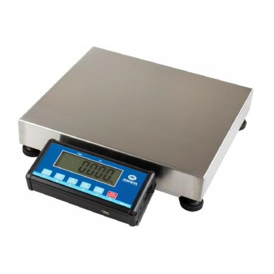
- Page 1 User/Technical Manual Contents subject to change without notice Version 04.12 8/2013...
-
Page 2: Table Of Contents
Check Counts (counts compare) in Counting mode....................23 Percent Weighing Mode (closed on PSE)......................24 Check Percent (percentage compare) in Percent weighing mode ................25 BMI Working Mode (closed on PSE) ....................... 26 Weight Fine-tune (closed on PSE) ........................26 HOLD Function (closed on PSE) ........................27 Details about Serial Communication ........................ - Page 3 Definitions ........................44 Troubleshooting ......................45 Replacement Parts ................错误!未定义书签。 One Year Limited Warranty ..............错误!未定义书签。...
-
Page 4: Introduction
1. INTRODUCTION General and Safety Information Risk of Electrical Shock: Disconnect all power sources before making cable connections to the floor scale platform or indicator. For use in dry environments only. The floor scale platform is very heavy. Use appropriate lift equipment. ... -
Page 5: Specifications
Specifications Model Max Capacity 150lb (60kg) Readability 0.05lb (0.02kg) Display Resolution 1:3000 Min Recommended Weight 1lb / 0.4kg Construction Die-cast aluminum base, stainless steel platform Weighing Units lb / kg / lb:oz Calibration unit Application Modes Weighing / Counting / Check weighing Display 6-digit, 7-segment, 1"... -
Page 6: Installation
Install the batteries or plug in the adapter. Now the scale is ready for use. S/S platform. The PSE indicator and platform are NTEP certified, making the scale capable of being used in Legal for Trade applications. However, the scale is not Legal for Trade until it has been certified and registered by an authorized Weights and Measures agent. -
Page 7: Overview Of Controls And Functions
3. OVERVIEW OF CONTROLS AND FUNCTIONS Indicator Display Character Definitions... -
Page 8: Indicator Display
Indicator Display - Scale is zeroed, gross weight is 0, tare is 0. - Scale is stable. NET - Display reading is net weight; tare is not 0. Total - Display data is accumulated total times, weight, pieces, or percentage. ... -
Page 9: Function Keys
Function Keys MODE DEFINITION Weighing, <3 seconds Enters or exits HOLD mode Counting, or >3 seconds Enters SETUP mode Percent mode <3 seconds Returns to last sub-menu Input data mode >3 seconds Inputs decimal point Menu selection mode Returns to last sub-menu Weighing, <3 seconds Sends output data via the serial port Counting, or... -
Page 10: Operation Menu Structure
4. Operation Menu Structure Enter Setup Mode 1. If there is a need to: configuration parameters, set user parameters, calibrate the scale, set current date or time, test some hardware, hold down the SETUP key for more than 3 seconds to enter into setup mode 2. - Page 11 SubMenu1 SubMenu2 Option Remark Setting Select the primary unit from kg or lb; defaulted PRIM. U t calibration standard weight unit is the primary unit. The division number under second unit, the max is 100- SECND. N 3000 1.25*(PRIM.N). 125000 10,000 Display weight at 10 times division number under 10N.
- Page 12 SubMenu1 SubMenu2 Option Remark Setting DSP. O VR Choose which weight as current initial zero point when current weight is over IZSM range: WEIGHT DSP.OVR=display initial zero is over; OV. I ZSM WEIGHT= current weight; DSP. O VR CAL. Z RO CAL.ZRO= calibration zero;...
- Page 13 SubMenu1 SubMenu2 Option Remark Setting COMPAR Yes/No=enable/disable data comparison function; Accumulation Mode selection: NO=no accumulation function; MANUAL=add up current number to accumulation ACCUMU MANUAL MANUAL memory after TATOL key is pressed; AUTO=automatically add up current number to FUNC accumulation memory after scale is stable and weight is AUTO over (NLD.RNG) GEO.
-
Page 14: User Submenu
USER Submenu: USER Sub- Sub- Option Remark Setting Menu1 Menu2 RESET Reset user parameters to factory setting 1200 2400 4800 BAUD. R T 9600 Selection of com1's baud rate 9600 19200 38400 Selection of com1's byte format: 8N1=8 data bits, No parity check bit, 1 stop bit; 7O1=7 data bits, 1 Odd parity check bit, 1 stop bit;... - Page 15 Sub- Sub- Option Remark Setting Menu1 Menu2 Yes/No=enable/disable output weight of 1% percentage. UPCTWT Prompt is ¡ 1% REF WT¡ COUNT Yes/No=enable/disable output counts. Prompt is ¡ QUANTITY¡ Yes/No=enable/disable output piece weight. Prompt is ¡ PIECE PCWT WT¡ Yes/No=enable/disable output height and BMI. Prompt is ¡...
- Page 16 Sub- Sub- Option Remark Setting Menu1 Menu2 Com2 output content and format set: MULTPL MULTPL= the following selected item in OUT2 will be output use defined format; SINGLE SINGLE= only displayed content and current status will be COM2 LAYOUT SCP-12 output, it¡s compatible with NCI-SCP01;...
- Page 17 Sub- Sub- Option Remark Setting Menu1 Menu2 Yes/No=enable/disable beep after a key pressed down NONE NONE=not beep; L. L OW L.Low=beep when lower than low limitation; BEEP IN.LMT=beep when in range of low and high limitation; COMPAR IN. L MT IN.
- Page 18 Sub- Sub- Option Remark Setting Menu1 Menu2 NONE Source of the executed command selection: COM.1 NONE=no any command will be executed; CMD.SRC COM1. 2 COM.1/.2= command from COM1/2 will be executed; COM.2 COM.1.2= command from COM1,COM2 will be executed; COM.1. 2 Auto off time: 0=not auto power off;...
-
Page 19: Cal Submenu
CAL Submenu: SUBMENU1 SUBMENU2 OPTION REMARK CAL. O N Seal switch is on or off CAL. O FF Only perform zero point calibration, then go to ZERO CAL. E ND to end Linear calibration point0: perform zero point CAL. P 0 calibration, this point can not be omitted. -
Page 20: Misc Submenu
MISC Submenu MISC SUBMENU1 REMARK Display ADC's code, this code can be after no-filter, filter1 or filter2; for more CODE details refer to section7 Display voltage; calibrate voltage; for more details refer to section7 DATE Display date and set date; for more details refer to section7 TIME Display time and set time;... -
Page 21: Operations
5. OPERATIONS Change working mode Press and hold the PRINT/FUNC key, then use key to choose and confirm to enter into weighing mode or counting mode. Normal Weighing Mode 1. Power on the scale by pressing the ZERO/ON/OFF key. 2. If the display stabilizes but doesn¡t show zero, press the ZERO/ON/OFF key to set new zero point. 3. -
Page 22: Zero
Table5-2: use LB as primary unit: Calibration division Display division value in different weight unit that can be used value lb:oz 0.0001lb Not available Not available 0.0001lb 0.002oz Not available 0.001 lb 0.0005 kg 0.5g 0.001 lb 0.02oz Not available 0.01 lb 0.005 kg 0.01 lb... -
Page 23: Check Weighing (Data Compare) In Normal Weighing Mode
3. Input the tare weight using the keys. After inputting the tare weight, press the TARE/PRESET key to confirm. ¡ NET¡ will be lit in the display. Note: Tare weight must be greater than zero and no more than the scale¡s maximum capacity. 4. -
Page 24: Counting Mode
total. The indicator will first display the times of accumulation (e.g. if this is the 5 accumulated ACC. 0 05 value, it will display ), and then display the accumulated sum total thus far, then it will display the load weight. Note: Only loads exceeding the minimum weight (default of 10d, where d = the scale¡s readability, see specifications) can be accumulated. -
Page 25: Check Counts (Counts Compare) In Counting Mode
keys to input a new piece weight, then press and hold the SETUP key for 4 seconds to input the decimal point. Press the TARE/PRESET key to confirm and return to counting mode. Note: If the input piece weight is less than 0.5d (where d = the scale¡s readability, see PWt. -
Page 26: Percent Weighing Mode (Closed On Pse)
HI or LO Announciator on the display will be lit with no audible beep. Audible beep parameters can be changed from their defaults in User Setup mode. Percent Weighing Mode (closed on PSE) In this mode, the scale will weigh the unit on the platform, calculate and display its percentage after the unit-percentage-weight of goods is obtained. -
Page 27: Check Percent (Percentage Compare) In Percent Weighing Mode
Pct. E r calculated unit-percentage-weight is less than 0.5d, the indicator will display and return back to percent weighing mode. b. Using the weigh samples weight when percentage is known InP. P ct Press the UNIT/DATA key, when is shown, use key to select SPL. -
Page 28: Bmi Working Mode (Closed On Pse)
After a reasonable limitation is set and compare is active, one of announciators HI, OK, LO will be displayed, and the beeper will sound according to the setting in USER-BEEP. BMI Working Mode (closed on PSE) 1. For BMI working Mode to be available, CONFIG-FUNC-BMI menu item should be set to YES. -
Page 29: Hold Function (Closed On Pse)
, and then press TARE/PRESET to confirm and exit to normal weighing mode. HOLD Function (closed on PSE) NOTE: In trade application, HOLD function should be prohibited! 1. HOLD function can be used to freeze the display number. In this mode, scale can catch a dynamic number, hold a stable number, or average an unstable number, then HOLD (freeze) this number temporary for the user to watch or record. - Page 30 scale will always catch and refresh with the largest positive number. To exit HOLD mode, press the SETUP key. b. Negative Peak HOLD: When USER-HOLD-HLD.MOD is set to NG.PEAK, the hold mode is negative peak hold mode. When the scale first enters this working mode, it will display the largest negative number that is from the time of zero-point set.
-
Page 31: Details About Serial Communication
Details about Serial Communication 1. COM1 is RS232, communication wires come from RS232 connector, and TXD0, RXD0 and GND are used. Please refer to section 9 for connector details 2. COM2 is USB used as a virtual RS232, communication wires come from USB connector, and TXD1, RXD1 and GND are used, Please refer to section 9 for connector details. - Page 32 0= eeprom OK 0=calibration ok 0=initial zero ok 0=battery ok 1= eeprom error 1=calibration error 1=initial zero error 1=low battery always 1 always 1 always 1 always 1 always 1 always 1 always 1 always 1 always 0 always 1 always 1 always 0 parity...
- Page 33 vii. Command: X<CR> (58h 0dh) Response: power off the scale, just like press down the ZERO/ON/OFF key to turn off the scale. viii. Command: all others Response: Unrecognized command <LF>? <CR><ETX> b. Summary of Command and Response: Command Response ASCII Read scale weight: ①<LF>^^^^^^^^U <CR><LF>...
- Page 34 indicator. If you want to watch ¡ real time¡ data, select fewer output contents and set higher baud rate for C<CR> --- USER-OUT1/2-LINE is set to LINE1/2/3/4 ¡ ¡ ---The number of blank lines is determined by USER-OUT1/2-LINE setting <ETX> --- Last byte of string frame b.
- Page 35 0=Within weighing range 1= Under zero 0= Within range 1= Outside zero capture range 0= Not at center of zero 1= Center of zero always 1 always 1 parity c. Summary of Command and Response: Command Response ASCII Read scale weight: ①normal data <STX>...
- Page 36 c. Key to symbols used: <ETX> End of TeXt character (03 hexadecimal). <LF> Line Feed character (0A hex). <CR> Carriage Return character (0D hex). Xxxxxx Weight characters from display including minus sign and out-of-range characters. Polarity character (ie ¡-¡ for negative, space for positive) Two status bytes.
-
Page 37: Calibration
6. Calibration Note: ① Before calibrating the scale, please prepare a standard weight (more than 10% of FS weight) for calibration. ② In the following steps, pressing ZERO/ON/OFF will show ¡ EXIT? ¡ , and pressing ZERO/ON/OFF again or pressing TARE/PRESET will exit the calibration 1. - Page 38 weight has been received. After this, the indicator will automatically continue to the next step. If this point can not be calibrated correctly (E.g. the weight load on the scale is too small, the CAL. E r input data is incorrect¡ ), it will display ¡ ¡...
- Page 39 format (¡ nn¡ is a decimal number of page, ¡ xxxx¡ is an hexadecimal value of parameter, e.g. 85E2 01-02 pages: zero code; CAL. P 1 03-04 pages: standard weight of CAL. P 1 05-06 pages: codes of CAL. P 2 07-08 pages: standard weight of CAL.
-
Page 41: Misc
7. MISC View ADC output Code In this mode, you can examine the stability of the weighing system, which is the increment value of ADC output code corresponding to the loaded weight. Note: ① The increment of ADC code for FS weight must be larger or equal to 10 times of the selected display division;... -
Page 42: View Or Set Date
current must be larger than 0.5A. Power off the indicator, remove the AC adaptor, connect the DC power to battery connector on main board, adjust voltage to about 5V, power on the indicator, and then enter into battery voltage display mode. CAL. -
Page 43: Test
8. TEST Display Test 1. Press and hold the SETUP key for more than 4 seconds to enter SETUP mode, using TEST-DSP. T ST keys to select item, then press TARE/PRESET to enter test display mode and all segments will be lit first. 2. -
Page 44: Connectors And Jumpers
9. Connectors and Jumpers 1. Load Cell Connector PIN # DEFINITION IN/OUT/POWER ELECTRICAL LEVEL Excitation + Power output Sense + Power input 5¡ 0.3 Vdc Excitation- Power ground 0Vdc Sense - Power input Signal + Signal Input 2.5¡ 0.3 Vdc Signal - Signal Input 2.5¡... - Page 45 4. SIO---Serial Input Output Connector PIN # DEFINITION IN/OUT/POWER ELECTRICAL LEVEL RS485 signal A (if RS485 installed) Input/output 0-5Vdc RS232 Transmit on UART0 Output -12 to +12Vdc RS232 Receive on UART0 Input -12 to +12Vdc Power ground 0Vdc RS485 signal B (if RS485 installed) Input/output 0-5Vdc 5.
-
Page 46: Definitions
10. Definitions Symbol Definitions CAP. - - - - Next displaying content is capacity CAL. O N - Calibration seal switch is on ON position CAL. P x - Calibration on point(x) CAL. E nd - Calibration is end COMP - To go to input COMPARE data mode HIGH - To input HIGH limitation data of comparison... -
Page 47: Troubleshooting
11. Troubleshooting SYMPTOM PROBABLE CAUSE REMEDY 1. Re-plug the AC adapter or rotate the plug 1. AC adapter is not connected securely to securely connect it to the scale Does not turn on. 2. Low battery 2. Replace the batteries 3. - Page 48 SYMPTOM PROBABLE CAUSE REMEDY Piece weight is error, it¡s too small (<0.5d), PWT. E R The weight on the platform is too small to Use a greater weight for the sample. define a valid reference weight 1. Max. CAPACITY is not same as marked on overlay Re-set CONFIG parameters per the Technical...
Need help?
Do you have a question about the PSE and is the answer not in the manual?
Questions and answers