
Related Manuals for Measurement Computing USB-234


Summary of Contents for Measurement Computing USB-234
- Page 1 USB-234 Analog and Digital I/O User's Guide Document Revision 3 October 2017 © Copyright 2017...
- Page 2 Other product and company names mentioned herein are trademarks or trade names of their respective companies. © 2015 Measurement Computing Corporation. All rights reserved. No part of this publication may be reproduced, stored in a retrieval system, or transmitted, in any form by any means, electronic, mechanical, by photocopying, recording, or otherwise without the prior written permission of Measurement Computing Corporation.
-
Page 3: Table Of Contents
What you will learn from this user's guide ......................5 Conventions in this user's guide ......................... 5 Where to find more information ......................... 5 Chapter 1 Introducing the USB-234 ........................6 Device features ..............................6 Functional block diagram ........................... 7 Chapter 2 Installing the USB-234 .......................... - Page 4 USB-234 User's Guide Power requirements ............................25 Power output ..............................25 USB specifications ............................25 Environmental ..............................26 Mechanical ............................... 26 Screw terminal connector ..........................26 Screw terminal pinout ............................27 Differential mode pinout ..............................27 Single-ended mode pinout ...............................27 Declaration of Conformity ........................28...
-
Page 5: Preface
Preface About this User's Guide What you will learn from this user's guide This user's guide describes the Measurement Computing USB-234 data acquisition device and lists device specifications. Conventions in this user's guide For more information Text presented in a box signifies additional information related to the subject matter. -
Page 6: Introducing The Usb-234
The USB-234 is a USB 2.0 high speed device that is compatible with USB 3.0 ports. The device is also compatible with USB 1.1 ports, but use with this older hardware is not recommended due to longer initialization times that can occur when the USB-234 is connected through USB 1.1 ports or hubs. -
Page 7: Functional Block Diagram
USB-234 User's Guide Introducing the USB-234 Functional block diagram Device functions are illustrated in the block diagram shown here. Figure 1. USB-234 functional block diagram... -
Page 8: Installing The Usb-234
Installing the hardware Install the software before you install your device The driver needed to run the USB-234 device is installed with the software. Therefore, you need to install the software package you plan to use before you install the hardware. -
Page 9: Calibrating The Hardware
Fax: 508-946-9500 to the attention of Tech Support Email: techsupport@mccdaq.com Calibrating the hardware The Measurement Computing Manufacturing Test department performs the initial factory calibration. Return the device to Measurement Computing Corporation when calibration is required. The recommended calibration interval is one year. -
Page 10: Chapter 3 Functional Details
Functional Details Analog input acquisition modes The USB-234 can acquire analog input data in two different modes – software paced and hardware paced. Software paced mode You can acquire one analog sample at a time in software paced mode. You initiate the A/D conversion with a software command. -
Page 11: External Components
USB-234 User's Guide Functional Details External components The external components on the USB-234 are shown in Figure 3. Screw terminal pins 1 to 16 LED Indicator Screw terminal pins 17 to 32 USB connector Figure 3. USB-234 external components Screw terminals The screw terminals provide the following connections (refer to Figure 4 and Figure 5 for pinout diagrams): ... - Page 12 USB-234 User's Guide Functional Details Figure 4. USB-234 differential pinout...
-
Page 13: Usb Connector
1. Wait 10 seconds to allow the device to attempt to recover from the error. 2. If the LED continues blinking, disconnect and reconnect the device. 3. If the error persists, contact Measurement Computing: Phone: 508-946-5100 and follow the instructions for reaching Tech Support... -
Page 14: Signal Connections
You can connect up to eight single-ended inputs or up to four differential inputs to screw terminals CH0H/CH0L through CH3H/CH3L . The input voltage range is ±10 V. Figure 6 shows the USB-234 analog input circuitry. Figure 6. USB-234 analog input circuitry The main analog input circuitry blocks are as follows: ... - Page 15 Input range The USB-234 has an input range of ±10 V. For DIFF mode, each AI should stay within ±10 V with respect to AGND, and the voltage between positive and negative inputs should be lower or equal to ±10 V. For SE mode, signals of ±10 V at any analog input terminal with respect to AGND are accurately measured.
-
Page 16: Analog Output
USB-234 User's Guide Functional Details Analog output Figure 8 shows the USB-234 analog output circuitry. Figure 8. USB-234 analog output circuitry The main analog output circuitry blocks are as follows: The protection circuit prevents damage of the buffers in case of a short circuit or an Protection –... - Page 17 Generating analog output data The USB-234 can generate analog output data in two different modes – software paced and hardware paced. ...
-
Page 18: Digital I/O
Power-on states At system startup and reset, the USB-234 sets all DIO lines to high-impedance inputs. The device does not drive the signal high or low. Each line has a weak pull-down resistor connected to it. -
Page 19: Trigger Input
The +5 V load should be connected between the terminal and . The current delivered by the USB-234 at the terminal is sourced from the USB connector. To meet the USB specifications, a maximum of 150 mA can be used from the... -
Page 20: Ground
USB-234 User's Guide Functional Details Figure 12. Connecting the +VO power source load The + 5 V power is always enabled and the voltage is present at the terminal when the device is in active mode. The +5 V power source is not available for about one second after the device is first connected to the USB connector or when the device is in suspend mode. -
Page 21: Mechanical Drawings
USB-234 User's Guide Functional Details Mechanical drawings Figure 13. Circuit board (top) and housing dimensions... -
Page 22: Chapter 4 Specifications
Chapter 4 Specifications All specifications are subject to change without notice. Typical for 25 °C unless otherwise specified. Specifications in italic text are guaranteed by design. Analog input Table 1. Analog input specifications Parameter Condition Specification A/D converter type Successive approximation ADC resolution 16 bits Sampling rate... -
Page 23: Analog Output
USB-234 User's Guide Specifications Analog output Table 3. Analog output specifications Parameter Condition Specification Resolution 16 bits, 1 in 65,536 Output range ±10 V Number of channels Update rate Hardware paced 5 kS/s simultaneous per channel max, hardware-paced Trigger sources Software, TRIG ±5 mA... -
Page 24: Digital Input
USB-234 User's Guide Specifications Digital input Table 5. Digital input specifications Parameter Condition Specification Input voltage range Power on 0 V to 5 V Power off 0 V to 3.3 V (Note 1) ±20 V on two lines per port (maximum of five... -
Page 25: Memory
Maximum load USB current <500 mA (Note 3) Note 2: A typical bus-powered hub provides 100 mA on its USB lines. The USB-234 does not work on a bus- powered hub. Note 3: The maximum power draw from all output terminals should be kept under 0.9 W to avoid overloading... -
Page 26: Environmental
USB-234 User's Guide Specifications Environmental Table 12. Environmental specifications (Indoor use only) Parameter Specification Operating temperature range 0 °C to 45 C Storage temperature range –40 °C to 85 °C Operating humidity range 5% to 95% RH, non-condensing Storage humidity range... -
Page 27: Screw Terminal Pinout
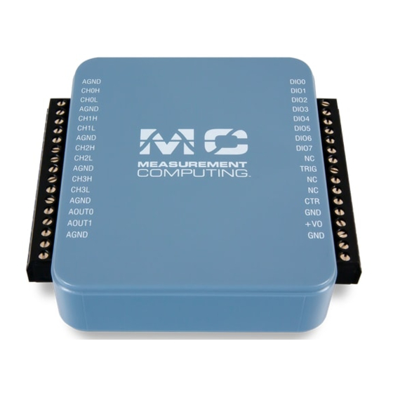
USB-234 User's Guide Specifications Screw terminal pinout Differential mode pinout Do not connect to terminal block pins labeled NC. Table 15. Screw terminal pinout Signal name Pin description Signal name Pin description AGND Analog ground DIO0 DIO bit 0 CH0H... -
Page 28: Declaration Of Conformity
Electrical equipment for measurement, control and laboratory use. Date of Issue: June 27, 2014 Measurement Computing Corporation declares under sole responsibility that the product USB-234 to which this declaration relates is in conformity with the relevant provisions of the following standards or other documents: EC EMC Directive 2004/108/EC: General Requirements, EN 61326-1:2006 (IEC 61326-1:2005). - Page 29 Measurement Computing Corporation 10 Commerce Way Suite 1008 Norton, Massachusetts 02766 (508) 946-5100 Fax: (508) 946-9500 E-mail: info@mccdaq.com www.mccdaq.com...
Need help?
Do you have a question about the USB-234 and is the answer not in the manual?
Questions and answers