
Related Manuals for Measurement Computing USB-1208HS


Summary of Contents for Measurement Computing USB-1208HS
- Page 1 USB-1208HS High-Speed Analog Input and Digital I/O User's Guide Document Revision 4 July 2014 © Copyright 2014...
- Page 2 © 2014 Measurement Computing Corporation. All rights reserved. No part of this publication may be reproduced, stored in a retrieval system, or transmitted, in any form by any means, electronic, mechanical, by photocopying, recording, or otherwise without the prior written permission of Measurement Computing Corporation.
-
Page 3: Table Of Contents
About this Manual ..........................5 Conventions ................................ 5 Where to find more information ......................... 5 Chapter 1 Introducing the USB-1208HS ....................... 6 Functional block diagram ........................... 6 Chapter 2 Installing the USB-1208HS ........................7 What comes with your shipment? ........................7 Hardware .................................. - Page 4 USB-1208HS User's Guide Screw terminal connector and pinout ....................... 21 Declaration of Conformity ........................23...
-
Page 5: Preface
Italic text is used for the names of manuals and help topic titles, and to emphasize a word or phrase. Where to find more information Additional information about USB-1208HS hardware is available on our website at www.mccdaq.com. You can also contact Measurement Computing Corporation by phone, fax, or email with specific questions. -
Page 6: Introducing The Usb-1208Hs
The USB-1208HS is a USB 2.0 high-speed device supported under popular Microsoft Windows operating systems. The USB-1208HS is compatible with both USB 1.1 and USB 2.0 ports (although the speed of the module maybe limited when using USB 1.1 ports). Functional block diagram USB-1208HS functions are illustrated in Figure 1. -
Page 7: Installing The Usb-1208Hs
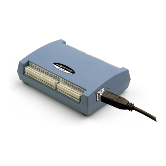
Refer to the Quick Start Guide for instructions. To connect the USB-1208HS to your system, turn your computer on, and connect the USB cable to a USB port on your computer or to an external USB hub connected to your computer. The USB cable provides power and communication to the USB-1208HS. -
Page 8: Calibrating The Usb-1208Hs
Installing the USB-1208HS Caution! Do not disconnect any device from the USB bus while the computer is communicating with the USB-1208HS, or you may lose data and/or your ability to communicate with the USB-1208HS. If the Status LED turns off The Status LED turns off if communication is lost between the device and the computer. -
Page 9: Functional Details
FIFO buffer on the USB-1208HS until you stop the scan. The FIFO buffer is serviced in blocks as the data is transferred from the USB-1208HS FIFO buffer to the memory buffer on your computer. -
Page 10: Screw Terminals
USB-1208HS User's Guide Functional Details Screw terminals The differential mode pinout is shown in Figure 3. Figure 3. Differential mode pinout The single-ended mode pinout is shown in Figure 4. Figure 4. Single-ended mode pinout Use 16 AWG to 30 AWG for signal connections. -
Page 11: Usb Connector
Activity LED The Activity LED indicates the communication status of the USB-1208HS. It blinks when data is transferred, and is off when the device is not communicating. This LED uses up to 10 mA of current and cannot be disabled. -
Page 12: External Clock I/O
The default configuration is pull-down. You can use the USB-1208HS digital I/O terminals to detect the state of any TTL-level input. Refer to the schematic shown in Figure 7. If you set the switch to the +5 V input, DIO0 reads TRUE (1). If you move the... - Page 13 Pull-up/down configuration Each of the 16 DIO bits on the USB-1208HS has a 47 kΩ pull-up/pull-down resistor. To configure these bits for either a +5 V pull-up or a 0 V pull-down option, open the device case to access the jumper labeled .
-
Page 14: Counter Input
USB-1208HS User's Guide Functional Details Figure 10. Pull-down and pull-up configurations Replace the top section of the case, and then fasten it to the bottom section with the four screws. For more information on digital signal connections For general information regarding digital signal connections and digital I/O techniques, refer to the Guide to Signal Connections (available on our web site at www.mccdaq.com/signals/signals.pdf). -
Page 15: Power Output
285 mA. Refer to Figure 3 and Figure 4 on page 10 for the location of this pin. Caution! The terminals are outputs. Do not connect to an external power supply or you may damage the USB-1208HS and possibly the computer. Ground The analog ground ( ) connections provide a common ground for all analog I/O channels. -
Page 16: Chapter 4 Specifications
Chapter 4 Specifications All specifications are subject to change without notice. Typical for 25 °C unless otherwise specified. Specifications in italic text are guaranteed by design. Analog input Table 1. Analog input specifications Parameter Condition Specification A/D converter Analog Devices AD7329 13-bit successive approximation type Input ranges Software-selectable... -
Page 17: Digital Input/Output
0 – 10 V (SE mode) ±3.29 typ, ±5.13 max Table 3 summarizes the noise performance for the USB-1208HS. Noise distribution is determined by gathering 50 kS with inputs tied to ground at the user connector. Samples are gathered at the maximum specified sample rate of 1 MS/s. -
Page 18: External Trigger
USB-1208HS User's Guide Specifications External trigger Table 6. External trigger specifications Parameter Specification Trigger source TRIG input Trigger mode Software-selectable for edge or level sensitive, rising or falling edge, high or low level. Power on default is edge sensitive, rising edge. -
Page 19: Counters
USB-1208HS User's Guide Specifications Counters Table 8. Counter specifications Parameter Specification Counter terminal names CTR0, CTR1 Counter type Event counter Number of channels Schmitt trigger, 33 Ω series resistor, 47 kΩ pull-down to ground Input type Schmitt trigger hysteresis 0.4 V to 1.2 V Input high voltage 2.2 V min... -
Page 20: Power
Mount Fuse. Spare fuse mounted in holder on PCB. Note 1: This is the total current consumption for USB-1208HS, including +5 V and digital output currents. Note 2: Output voltage range assumes input power is within specified limits. USB specifications Table 12. -
Page 21: Mechanical
USB-1208HS User's Guide Specifications Mechanical Table 14. Mechanical specifications Parameter Specification Dimensions (L × W × H) 5.00 × 3.53 × 1.40 in. (127 × 89.9 × 35.6 mm) Screw terminal connector and pinout Table 15. Connector specifications Parameter Specification... - Page 22 USB-1208HS User's Guide Specifications Table 17. Differential mode pinout Signal name Signal name AIN0 + AGND AIN0 - AGND AGND AIN1 + AGND AGND AIN1 - AICKI AGND AICKO AIN2 + AGND AIN2 - TRIG AGND AIN3 + CTR0 AGND...
- Page 23 Norton, MA 02766 Category: Electrical equipment for measurement, control and laboratory use. Measurement Computing Corporation declares under sole responsibility that the products USB-1208HS to which this declaration relates is in conformity with the relevant provisions of the following standards or other documents: EC EMC Directive 2004/108/EC: General Requirements, EN 61326-1:2006 (IEC 61326-1:2005).
- Page 24 Measurement Computing Corporation 10 Commerce Way Suite 1008 Norton, Massachusetts 02766 (508) 946-5100 Fax: (508) 946-9500 E-mail: info@mccdaq.com www.mccdaq.com...
Need help?
Do you have a question about the USB-1208HS and is the answer not in the manual?
Questions and answers