Table of Contents
Advertisement
Quick Links
Advertisement
Table of Contents

Subscribe to Our Youtube Channel
Related Manuals for Measurement Computing USB-2533


Summary of Contents for Measurement Computing USB-2533
- Page 2 USB-2533 User's Guide Document Revision 2, March, 2007 © Copyright 2007, Measurement Computing Corporation...
- Page 3 Measurement Computing. Thank you for choosing a Measurement Computing product—and congratulations! You own the finest, and you can now enjoy the protection of the most comprehensive warranties and unmatched phone tech support. It’s the embodiment of our mission: To provide PC-based data acquisition hardware and software that will save time and save money.
- Page 4 Information furnished by Measurement Computing Corporation is believed to be accurate and reliable. However, no responsibility is assumed by Measurement Computing Corporation neither for its use; nor for any infringements of patents or other rights of third parties, which may result from its use. No license is granted by implication or otherwise under any patent or copyrights of Measurement Computing Corporation.
-
Page 5: Table Of Contents
Chapter 1 Introducing the USB-2533 ........................8 Overview: USB-2533 features..........................8 Software features ..............................8 Chapter 2 Installing the USB-2533 ........................9 What comes with your USB-2533 shipment?.....................9 Hardware ..................................9 Optional components ................................ 9 Signal conditioning accessories ............................10 Additional documentation..............................10 Unpacking the USB-2533..........................10 Installing the software ............................10... - Page 6 Counter inputs ..............................32 Mapped channels ................................33 Counter modes .................................33 Debounce modes................................34 Timer outputs..............................37 Example: Timer outputs..............................37 Using multiple USB-2533s per PC........................37 Chapter 5 Calibrating the USB-2533 ........................38 Chapter 6 Specifications............................39 Analog input ..............................39 Accuracy ..................................39 Thermocouples ................................40 Digital input/output............................40 Counters................................41 Input sequencer..............................41...
-
Page 7: Preface
What you will learn from this user's guide This user's guide explains how to install, configure, and use the USB-2533 so that you get the most out of its analog input, thermocouple (TC) input, digital I/O, and counter/timer I/O features. -
Page 8: Introducing The Usb-2533
USB bus. The USB-2533 provides either 32 differential or 64 single-ended analog inputs with 16-bit resolution from its 40-pin connectors. It offers seven software-selectable analog input ranges of ±10 V, ±5 V, ±2 V, ±1 V, ±0.5 V, ±0.2 V, and ±0.1V. -
Page 9: Installing The Usb-2533
USB cable (2-meter length) Optional components Cables and signal conditioning accessories that are compatible with the USB-2533 are not included with USB- 2533 orders, and must be ordered separately. If you ordered any of the following products with your board, they should be included with your shipment. -
Page 10: Signal Conditioning Accessories
Installing the hardware To connect the USB-2533 to your system, turn your computer on, and connect the USB cable to a USB port on your computer or to an external USB hub that is connected to your computer. The USB cable provides power and communication to the USB-2533. -
Page 11: Configuring The Hardware
(bottom LED) blinks during device detection and initialization, and then remains solid as long power LED as the USB-2533 has sufficient power. If the power provided from the USB is not sufficient, the LED turns off, indicating you need a PS-9V1AEPS-2500 power supply. -
Page 12: Connecting The Board For I/O Operations
ESD bags and cartons, and related procedures. Avoid touching board surfaces and onboard components. Only handle boards by their edges. Make sure the USB-2533 does not come into contact with foreign elements such as oils, water, and industrial particulate. -
Page 13: 68-Pin Scsi Connector Differential And Single-Ended Pin Outs (P5)
USB-2533 User's Guide Installing the USB-2533 68-pin SCSI connector differential and single-ended pin outs (P5) The 68-pin SCSI connector provides 16 single-ended analog channels or eight differential analog channels. Refer to the "40-pin header connector pin outs" section starting on page 16 to learn the pin outs for accessing up to 64 single-ended/32 differential analog channels using the P5 and P6 connectors. - Page 14 USB-2533 User's Guide Installing the USB-2533 68-pin SCSI connector pin out (labeled P5 on the board) 8-channel differential mode Signal name Signal name • • ACH0 HI ACH0 LO AGND • • ACH1 HI • • ACH1 LO AGND • •...
-
Page 15: Tb-100 Terminal Board Connector To Scsi Connector Pin Out
USB-2533 User's Guide Installing the USB-2533 TB-100 terminal board connector to SCSI connector pin out SCSI connector pin out assignments for TB-7 terminal board connector (8-channel differential analog signals in parentheses) TB2 screw terminals SCSI pin TB1 screw terminal SCSI pin... -
Page 16: 40-Pin Header Connector Pin Outs
USB-2533 User's Guide Installing the USB-2533 40-pin header connector pin outs Analog channels pin out (J5 and J6) This edge of the header is closest to the center of the USB- 2533. Pins 2 and 40 are labeled on the board silkscreen. - Page 17 USB-2533 User's Guide Installing the USB-2533 40-pin header connectors pin out (labeled J5 and J6) 32-channel differential mode Analog Analog Analog Analog channel channel channel channel ACH11 LO ACH11 HI ACH19 LO ACH27 LO ACH10 LO ACH10 HI ACH19 HI...
- Page 18 Digital ports, counters, timers, triggers, pacer clocks pin out (J7 and J8) You can use the 40-pin connector headers labeled J7 and J8 to connect digital ports, counters, timers, triggers, pacer clocks, and other signals. USB-2533 40-pin header connectors pin out (labeled J7 and J8) Digital channel Digital channel...
-
Page 19: Four-Channel Tc Terminal Pin Out (Tb7)
USB cable Figure 1. Four C40FF-x cables connected to J5 through J8 40-pin connectors In all scenarios, a USB cable (MCC p/n CA-USB2.0) is used to connect the USB-2533 to a USB port on the host PC. Four-channel TC terminal pin out (TB7) The TB7 terminal block can be used to connect up to four TCs. -
Page 20: Cabling
Figure 3. CA-68-3R cable Figure 4. CA-68-3S and CA-68-6S cable Use one or more C40FF-x- ribbon cable(s) (Figure 5) to connect signals to one or more of the USB-2533's 40- pin header connectors. The red stripe identifies pin # 1... -
Page 21: Field Wiring And Signal Termination
Installing the USB-2533 Field wiring and signal termination You can use the following Measurement Computing screw terminal board to terminate field signals and route them into the USB-2533 board using the CA-68-3R, CA-68-3S, or CA-68-6S cable: : Termination board with screw terminals. Details on this product are available on our web site at TB-100 www.mccdaq.com/cbicatalog/cbiproduct.asp?dept_id=98&pf_id=1787. -
Page 22: Programming And Developing Applications
2, your USB-2533 should now be installed and ready for use. Although the board is part of the larger Measurement Computing hardware family, in general there may be no correspondence among registers for different boards. Software written at the register level for other models will not function correctly with your board. -
Page 23: Functional Details
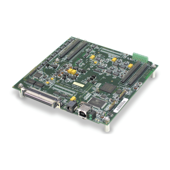
USB-2533 components These USB-2533 components are shown in Figure One USB port One external power connector... - Page 24 External power connector Although the USB-2533 is powered by a USB port on a host PC, an external power connector is available when the host PC’s USB port cannot supply adequate power, or if you prefer to use a separate power source.
-
Page 25: Usb-2533 Block Diagram
USB-2533 User's Guide Functional Details USB-2533 block diagram Figure 7 is a simplified block diagram of the USB-2533. This board provides all of the functional elements shown in the figure. 16-bit, 1 MHz converter Figure 7. USB-2533 functional block diagram... -
Page 26: Synchronous I/O - Mixing Analog, Digital, And Counter Scanning
Synchronous I/O – mixing analog, digital, and counter scanning The USB-2533 can read analog, digital, and counter inputs, while generating digital pattern outputs at the same time. Digital and counter inputs do not affect the overall A/D rate because these inputs use no time slot in the scanning sequencer. - Page 27 USB-2533 User's Guide Functional Details In this mode, oversampling is programmable up to 16384 oversamples per channel in the scan group. When oversampling is applied, it is applied to all analog channels in the scan group, including temperature and voltage channels.
- Page 28 PC is 2.167 MS/s. Some slower PCs may have a problem with data bandwidths greater than 6 MS/s. The USB-2533 has an onboard 1 MS buffer for acquired data. Example: Sampling digital inputs for every analog sample in a scan group The scan is programmed pre-acquisition and is made up of six analog channels (Ch0, Ch2, Ch5, Ch11, Ch13, Ch15) and four digital channels (16-bits of digital input, three counter inputs.) Each of the analog channels can...
-
Page 29: Thermocouple Input
As a result, the USB-2533 measures channels with TCs attached at a rate from 50 Hz to 10 kHz, depending on how much over-sampling is selected. -
Page 30: Digital I/O
Hardware analog triggering The USB-2533 uses true analog triggering in which the trigger level you program sets an analog DAC, which is then compared in hardware to the analog input level on the selected channel. This guarantees an analog trigger latency that is less than 1 µs. -
Page 31: Digital Triggering
Software-based triggering usually results in long period of inactivity between the trigger condition being detected and the data being acquired. However, the USB-2533 avoids this situation by using pre-trigger data. When software-based-triggering is used, and the PC detects the trigger condition—which may be thousands of readings after the actual occurrence of the signal—the USB-2533 driver automatically looks back to the... -
Page 32: Pre-Triggering And Post-Triggering Modes
Counter inputs Four 32-bit counters are built into the USB-2533. Each counter accepts frequency inputs up to 20 MHz. The counters can concurrently monitor time periods, frequencies, pulses, and other event driven incremental occurrences directly from pulse-generators, limit switches, proximity switches, and magnetic pick-ups. -
Page 33: Mapped Channels
Sets the signal on the mapped counter input to latch the count. By default, the start of scan signal—a signal internal to the USB-2533 pulses once every scan period to indicate the start of a scan group—latches the count, so the count is updated each time a scan is started. -
Page 34: Debounce Modes
USB-2533 User's Guide Functional Details Gating "on" mode Sets the gating option to "on" for the mapped channel, enabling the mapped channel to gate the counter. Any counter can be gated by the mapped channel. When the mapped channel is high, the counter is enabled. - Page 35 USB-2533 User's Guide Functional Details Figure 14. Debounce module – trigger after stable mode The following time periods (T1 through T5) pertain to Figure 14. In trigger after stable mode, the input signal to the debounce module is required to have a period of stability after an incoming edge, in order for that edge to be accepted (passed through to the counter module.) The debounce time for this example is equal to T2 and T5.
- Page 36 USB-2533 User's Guide Functional Details Debounce mode comparisons Figure 16 shows how the two modes interpret the same input signal, which exhibits glitches. Notice that the trigger before stable mode recognizes more glitches than the trigger after stable mode. Use the bypass option to achieve maximum glitch recognition.
-
Page 37: Timer Outputs
Using multiple USB-2533s per PC USB-2533 features can be replicated up to four times, as up to four devices can be connected a single host PC. The serial number on each USB-2533 distinguishes one from another. You can operate multiple USB-2533 boards synchronously. -
Page 38: Calibrating The Usb-2533
Calibrating the USB-2533 Every range of a USB-2533 device is calibrated at the factory using a digital NIST traceable calibration method. This method works by storing a correction factor for each range on the unit at the time of calibration. For analog inputs, the user can adjust the calibration of the board while it is installed in the acquisition system. -
Page 39: Specifications
Chapter 6 Specifications Typical for 25 °C unless otherwise specified. Specifications in italic text are guaranteed by design. Analog input Table 1. Analog input specifications A/D converter type Successive approximation Resolution 16 bits Number of channels 64 single-ended/32 differential, software-selectable Input ranges (SW programmable) Bipolar: ±10 V, ±5 V, ±2 V, ±1 V , ±0.5 V, ±0.2 V, ±0.1 V Maximum sample rate... -
Page 40: Thermocouples
USB-2533 User's Guide Specifications Noise reflects 10,000 samples at 1 MHz, typical, differential short. Note 4: Thermocouples Table 3. TC types and accuracy (Note 3) TC type Temperature range (°C) Accuracy (±°C) Noise typical (±°C) -200 to + 760 -200 to + 1200... -
Page 41: Counters
USB-2533 User's Guide Specifications Counters Counter inputs can be scanned based on an internal programmable timer or an external clock source. Table 5. Counter specifications Channels Four independent Resolution 32-bit Input frequency 20 MHz maximum Input signal range -5 V to 10 V Input characteristics 10 kΩ... -
Page 42: Trigger Sources And Modes
USB-2533 User's Guide Specifications Trigger sources and modes Table 7. Trigger sources and modes Input scan trigger sources Single channel analog hardware trigger Single channel analog software trigger External-single channel digital trigger (TTL TRG input) Digital Pattern Trigger Counter/Totalizer Trigger... -
Page 43: External Power
USB-2533 User's Guide Specifications External power Table 10. External power specifications (Note 5) Connector Switchcraft # RAPC-712 6 to 16 VDC (used when USB port supplies insufficient Power range power, or when an independent power supply is desired) 200 V for 10 seconds, maximum... -
Page 44: 68-Pin Scsi Connector Pin Outs
USB-2533 User's Guide Specifications 68-pin SCSI connector pin outs Table 15. 68-pin SCSI connector pin out (labeled P5 on the board) 16-channel single-ended mode Function Function ACH0 ACH8 AGND ACH1 ACH9 AGND ACH2 ACH10 AGND ACH3 ACH11 AGND SGND (low level sense - not for general use) -
Page 45: 40-Pin Header Connector Pin Outs
USB-2533 User's Guide Specifications Table 16. 68-pin SCSI connector pin out (labeled P5 on the board) 8-channel differential mode Function Function ACH0 HI ACH0 LO AGND ACH1 HI ACH1 LO AGND ACH2 HI ACH2 LO AGND ACH3 HI ACH3 LO... - Page 46 USB-2533 User's Guide Specifications Table 17. 40-pin header connector pinout (labeled J5 on the board) 64-channel single-ended mode Function Function ACH27 ACH19 ACH26 ACH18 AGND AGND ACH3 ACH11 ACH2 ACH10 ACH17 ACH25 ACH16 ACH24 ACH1 ACH9 ACH0 ACH8 AGND AGND...
- Page 47 USB-2533 User's Guide Specifications Table 19. 40-pin header connector pinout (labeled J6 on the board) 64-channel single-ended mode Function Function ACH43 ACH59 ACH35 ACH51 AGND ACH58 ACH42 ACH50 ACH34 ACH57 AGND ACH49 ACH41 ACH56 ACH33 ACH48 ACH40 AGND ACH32 ACH63...
- Page 48 USB-2533 User's Guide Specifications Table 21. 40-pin header connector pin out (J7 on the board) Function Function XAPCR TTL TRG +5 V (see Note TMR1 TMR0 CNT1 CNT0 CNT3 CNT2 Table 22. 40-pin header connector pin out (J8 on the board)
-
Page 49: Tc Connector Pin Out (Tb7)
USB-2533 User's Guide Specifications TC connector pin out (TB7) Standoff Figure 20. TC terminal pin out (labeled TB7) - Page 50 Measurement Computing Corporation 10 Commerce Way Suite 1008 Norton, Massachusetts 02766 (508) 946-5100 Fax: (508) 946-9500 E-mail: info@mccdaq.com www.mccdaq.com...
Need help?
Do you have a question about the USB-2533 and is the answer not in the manual?
Questions and answers