Table of Contents
Advertisement
Quick Links
Download this manual
See also:
User Manual
Advertisement
Table of Contents

Related Manuals for AccuMac AM8010


Summary of Contents for AccuMac AM8010
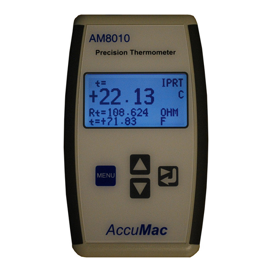
- Page 1 AM8010 Precision Thermometer User’s Guide Please download the latest version at www.accumac.com Rev. 201609V3...
-
Page 2: Table Of Contents
AM8010 Precision Thermometer User’s Guide Table of Contents Package List ..................2 Important Safety Information .............. 2 Introduction ..................3 General Operation ................6 Mode Switch Setting ................6 Battery Installation ................6 Power with External Adapter and USB ..........7 Sensor Connection ................ -
Page 3: Package List
Cool Edge USB Viewer USB driver 2 Important Safety Information AM8010 is a high accuracy temperature measurement and calibration instrument that can be used in laboratories and the field. Users should read and understand the following Warning to avoid electrical shocks and injuries. -
Page 4: Introduction
(PRT) sensors for temperature measurement. Its temperature calculation is based on ITS-90 or CVD formula. AM8010 Precision Thermometer can be connected to a computer using an USB cable to do real time temperature data acquisition. The main features of AM8010 Precision Thermometer include the followings:... -
Page 5: Specifications
AM8010 Precision Thermometer User’s Guide 3.1 Specifications Temperature Range -200 °C to 850 °C, depends on PRT sensor ±0.04 °C at -200 °C Accuracy (meter only) ±0.03 °C at 0°C ±0.04 °C at 232 °C ±0.05 °C at 420 °C ±0.06 °C at 660 °C... - Page 6 : INCREMENT KEY, : DECREMENT KEY, and : RIGHT SHIFT and RETURN KEY. The top panel of AM8010 is shown in Figure 3-2. There are three interfaces: “SENSOR,“USB or EXT POWER” and power switch “OFF/ON”. Figure 3-2: AM8010 Top Panel A foldable tilt foot support is mounted on the back of AM8010.
-
Page 7: General Operation
Chapter 7. The procedures to set this switch are as followings: 1. Turn off AM8010. 2. Open the battery cover at the back side of AM8010. Mode Switch, which is a sliding switch, is located besides the battery holder. -
Page 8: Power With External Adapter And Usb
3. Plug the adapter to AC 100V ~ 240V power point. Switch on the AC power. 4. If AM8010 is not powered on, switch it on. If AM8010 is already powered by batteries and the power switch is on, the backlight of LCD should illuminate. -
Page 9: Power On/Off Control
4.5 Power On/Off Control The power switch is on the top panel of AM8010. It is marked with “OFF/ON” text. Users can follow the sign to turn the meter on/off. 4.6 Display of Measurement Results The temperature measurement results are displayed on the LCD screen. -
Page 10: Touchpad Operation
4.7 Touchpad Operation There are four touch keys on AM8010 front panel. These touch keys are used for scrolling up/down measurement data, or for sensor parameter adjustment and calibrations. -
Page 11: Connecting To A Computer Using Usb Interface
5 Connecting to a Computer Using USB Interface AM8010 is designed with a USB v2.0 compatible interface (Mini B type) and it can be connected to a PC. The USB interface serves two important functions as a power source (see Chapter 4.3) and a link for data acquisition. - Page 12 AM8010 Precision Thermometer User’s Guide e) Select “No, not this time” , then click on “Next”, f) Select “Install from a list or specific location (Advanced)” and then click on “Next”, Rev. 201609V3 11/30...
- Page 13 AM8010 Precision Thermometer User’s Guide g) Use “Browse” to find the driver in E. refer to the above figure, then click on “Next”, h) Select “Continue Anyway”, the computer may request for another file “FTD2XX.sys”. i) Use “Browse” to search E drive to find and select FTD2XX.sys,click on “OK”.
- Page 14 AM8010 Precision Thermometer User’s Guide j) Click “Finish” to end the installation. k) The computer should show “Your new hardware is ready to use” to indicate that the installation is finished. Rev. 201609V3 13/30...
-
Page 15: Cool Edge Usb Viewer Software
Viewer” from the CD provided to the desktop. b) Connect a USB cable between the computer and AM8010. c) Turn on AM8010, after a few seconds, the first line of AM8010 LCD display will show “USB”. d) Double click the icon of “Cool Edge USB Viewer” on the desktop to start the software. - Page 16 AM8010 Precision Thermometer User’s Guide f) Click on the “Start” button, the software should show the measurement data as follows: g) Users can use the “Data Saving” function at the right side to save the data if needed. The first step is to set the sampling rate.
-
Page 17: Sensor Parameters Input/Adjustment
0. Refer to ITS-90 for details). After users input/adjust the correct parameters the sensor type is displayed on the LCD of AM8010 and the parameters are used in the calculation. Note: Users need to set the parameters corresponding to the sensor to get the optimal measurement. - Page 18 AM8010 Precision Thermometer User’s Guide 3. Power on AM8010. If a sensor is connected to AM8010,the LCD should display the measurement reading. See the following figure as an example. If no sensor is connected users can still set parameters of a sensor.
- Page 19 AM8010 Precision Thermometer User’s Guide SENSOR = IPRT IPRT Menu = Exit Enter = Yes 7. As illustrated in the above Figure, the first line shows the current sensor type. If the connected sensor type is different from the current setting (IPRT for example), the sensor type needs to be changed.
- Page 20 AM8010 Precision Thermometer User’s Guide The user can adjust Rtp, A4, B4, A, B and C in this section. MENU Press key to select and press key to go back to previous screen when adjustments are done. The following are examples of setting R0 and A4 values.
- Page 21 AM8010 Precision Thermometer User’s Guide MENU this value, press to quit the adjustment; if users want to save this new value, press . The new R0 value will be saved into the meter. The program will go back to 6.1.8.
- Page 22 MENU v. Press to exit without saving. Press to save the new a4 value to AM8010. The other parameters can be adjusted in a similar way as the above. Rev. 201609V3 21/30...
-
Page 23: Calibration
100.0038 ohm resistance is used as an example. It is suggested to use external power adapter or to connect the AM8010 to a USB interface on a running computer during calibration. If battery power is used make sure the batteries are not running low. - Page 24 AM8010 Precision Thermometer User’s Guide * CALIB MENU CALIBRATION Enter = Yes 2. Press key,the display will show: Rs = 99.9999 Rt = 99.9888 3. The second line shows the internal reference Rs value (value may be different from meter to meter). The third line shows the current external standard resistor resistance reading Rt = 99.9888 ohm, which is not equal to the real external standard...
-
Page 25: System Calibration
MENU the new Rs. Press key to exit without saving. After the calibration, turn the AM8010 off and change back the Mode Switch to Measurement Mode. 7.2 System Calibration System Calibration is based on the Instrument Calibration. It is to integrate a particular PRT sensor with AM8010 after Instrument Calibration to form a temperature measurement system. - Page 26 7.2.1 Calibration with IPRT (high precision 100 ohm or industrial 100 ohm Platinum Resistance Thermometer with α=0.00385) 1. Turn off power of AM8010, make sure it is at Measurement Mode (see Chapter 4.1 for details). 2. Connect the sensor to AM8010. Power on AM8010, and put the sensor into temperature bath or fix point cells.
- Page 27 R(t)=R(0ºC)*[1+At+Bt +C(t-100)t Then C value can be calculated. 5. Key in the A,B,C and R0 to AM8010. The system calibration is done. 6. Turn off the power after calibration. 7.2.2 Calibration of PRT (high precision 100 ohm or standard 100 ohm Platinum Resistance Thermometer with temperature coefficient α=0.003925(W...
- Page 28 The sensor’s parameters a, b and c can be calculated based on the above data and formula. 5. Key in the a, b, c and Rtp into AM8010. After the parameters are saved, the system calibration is done. More details about the coefficients and temperature calculations can be found in ITS-90 standard.
-
Page 29: Sensor Connector Assembly And Pin Configuration
AM8010 Precision Thermometer User’s Guide 8 Sensor Connector Assembly and Pin Configuration The sensor connector is a 5-pin round connector with retention relief. The assembly drawing is shown in the following figure. Figure 8-1: sensor connector assembly drawing. The pin configuration of the connector is shown as in Figure 8-2. -
Page 30: Limited Warranty & Limitation Of Liability
The material contained in this document is provided “as is,” and is subject to being changed, without notice, in future editions. AccuMac shall not be liable for errors or for incidental or consequential damages in connection with the furnishing, use, or performance of this document or of any information contained herein.
Need help?
Do you have a question about the AM8010 and is the answer not in the manual?
Questions and answers