Advertisement
This guide provides you with the basic information required to start up your SMC Flex controller. When reading
this document, look for this symbol "Step x" to guide you through the four basic steps required to install, start-up,
and program the SMC Flex.
The information provided in this Quick Start guide does not replace the User Manual which can be ordered or
downloaded by visiting www.ab.com. The Quick Start guide assumes the installer is a qualified person with
previous experience and basic understanding of electrical terminology, configuration procedures, required
equipment, and safety precautions.
For safety of maintenance personnel as well as others who might be exposed to electrical hazards associated with
maintenance activities, follow all local safety related work practices (for example, the NFPA 70E, Part II in the
United States). Maintenance personnel must be trained in the safety practices, procedures, and requirements that
pertain to their respective job assignments.
For detailed SMC Flex information including set-up, programming, precautions, and application considerations,
refer to the following documentation.
For product technical support:
™
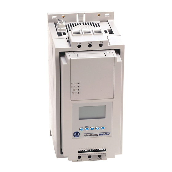
SMC
FLEX
BULLETIN 150
Title
SMC Flex User Manual
SMC Flex Application Guide 150-AT002*
Online Support
Telephone Support
Publication Number
150-UM008*
www.ab.com/support
440-646-5800 (option 2, option 4 or use
direct dial code 804)
QUICK START
Availability
www.ab.com/literature
www.ab.com/literature
Advertisement
Table of Contents

Related Manuals for Rockwell Automation SMC FLEX


Summary of Contents for Rockwell Automation SMC FLEX
- Page 1 BULLETIN 150 This guide provides you with the basic information required to start up your SMC Flex controller. When reading this document, look for this symbol “Step x” to guide you through the four basic steps required to install, start-up, and program the SMC Flex.
-
Page 2: Step 1 - Read The General Precautions
SMC™ Flex Quick Start Step 1 - Read the General Precautions WARNING • Only personnel familiar with the controller and associated machinery should plan or implement the installation, start-up, and subsequent maintenance of the system. Failure to do this may result in personal injury and/or equipment damage. - Page 3 SMC™ Flex Quick Start NOTICE • The controller contains ESD- (electrostatic discharge) sensitive parts and assemblies. Static control precautions are required when installing, testing, servicing, or repairing the assembly. Component damage may result if ESD control procedures are not followed. If you are not familiar with static control procedures, refer to applicable ESD protection handbooks.
-
Page 4: Step 2 - Installation
SMC™ Flex Quick Start Step 2 - Installation Mounting Enclosure Ratings Standard Device Rating IP00 (NEMA Open Type) Minimum Required Enclosure IP23 (NEMA Type 1) Recommended Enclosure IP54 (NEMA Type 12), sizing guide in User Manual Enclosure Internal Temperature -5…50 °C (23…122 °F) Orientation and Clearance Mounting Orientation Vertical... - Page 5 SMC™ Flex Quick Start Dimensions For detailed dimensions, please refer to the SMC Flex User Manual. Lang SMC-Flex 23 24 25 26 27 28 29 30 31 32 33 34 11 12 13 14 15 16 17 18 19 20 21 22 Dimensions are in millimeters (inches).
-
Page 6: Power Wiring
SMC™ Flex Quick Start Power Wiring Refer to the product nameplate or the SMC Flex User Manual for device specific information. SMC Rating Lug Kit Wire Strip Conductor Max. No. Lugs/Pole Tightening Torque Cat. No. Length Range Line Side Load Side... -
Page 7: Control Wiring
SMC™ Flex Quick Start Control Wiring Refer to the product nameplate for additional details. Depending on the specific application, additional control circuit transformer VA capacity may be required. Controllers rated 5…480 A Control power is connected to the product through terminals 11 and 12. Conductor Range 0.75…2.5 mm (18…14 AWG) -
Page 8: Typical Wiring Diagrams
SMC™ Flex Quick Start Typical Wiring Diagrams Typical Power Wiring Examples Diagrams per NEMA Symbology Line Connection with Delta Connection with Delta Connection with Isolation Contactor Isolation Contactor Shorted SCR Protection (Default Mode) (Optional Mode) (Optional Mode) T6 T4 T5 Motor Motor Motor... - Page 9 Factory Default Position 110/120 VAC Supply Jumpers 12 13 14 15 16 17 18 21 22 Hold In Aux#1 SMC Flex Control Terminals Optional Configuration 220/240 VAC Aux#2 Aux#3 Aux#4 24 25 26 28 29 30 31 32 33 34...
- Page 10 Aux#1 – Set for Normal Option Stop Aux#4 – Set fot Alarm Start 12 13 14 15 16 17 18 21 22 Hold In Aux#1 SMC Flex Control Terminals Aux#2 Aux#3 Aux#4 24 25 26 28 29 30 31 32 33 34 Alarm Indication N (L-) Fig 1.x...
-
Page 11: Step 3 - Basic Programming
SMC™ Flex Quick Start Step 3 - Basic Programming The SMC-Flex controller can be programmed with the built-in keypad and LCD display or with an optional Bulletin 20-HIM-xx LCD human interface module. Menu Structure Hierarchy Main Menu See File Structure Below for Parameters additional details Power Up and Status Display... - Page 12 Parameter # 32 - Stop Mode Soft Stop, Linear Speed, SMB, Soft Stop Allows the user to program the SMC Flex controller for the type of stopping that best fits the application. Accu-Stop, Pump Stop Parameter # 33 - Stop Time 0.0…120 s...
-
Page 13: Step 4 - Operation And Troubleshooting
3. Check control wiring 4. Apply control power 5. Test local start/stop control Monitoring The SMC Flex controller has built in diagnostics and metering functions which can be accessed through a local or remote LCD display. Step Action From any menu, Press Esc to get to the MAIN Device display. - Page 14 SMC™ Flex Quick Start Troubleshooting - Abbreviated Listing For a complete list of fault codes and troubleshooting tips, refer to the SMC Flex User Manual. Display Fault Fault Code Enabled Possible Causes Possible Solutions Line Fault with 1, 2, 3...
-
Page 15: Repair Parts
Control Power ➀ One piece provided per part number. ➁ Three-phase power pole structure provided per part no. ➂ One-phase power pole provided per part no. ➃ Refer to Appendix D in the SMC Flex User Manual, for installation instructions. - Page 16 Publication 150-QS001G-EN-P — August 2008 40055-217-01 (7) Superecedes Publication 150-QS001F-EN-P — November 2006 Copyright ©2008 Rockwell Automation, Inc. All Rights Reserved. Printed in USA.
Need help?
Do you have a question about the SMC FLEX and is the answer not in the manual?
Questions and answers