
Related Manuals for Newco CX-3


Summary of Contents for Newco CX-3
- Page 1 PN 780108_Rev 2017-02-13 OPERATION MANUAL NEWCO’S MODEL CX-3 SPECIALTY DRINK SINGLE CUP BREWER WITH AUTO EJECT SYSTEM 3650 NEW TOWN BLVD. ST. CHARLES MO 63301 WWW.NEWCOCOFFEE.COM 1.800.325.7867...
-
Page 2: Table Of Contents
Table of Contents Introduction & NEWCO Product Warranty Page: 4 Machine Dimensions & Specifications Page: 5 Machine Features Page: 7 Plumbing connections Page: 8 Electrical Hook-Up Page: 8 Installation Instructions Page: 9 Set-Up Instructions Page: 10 Programming Instructions Page: 11 Service Notes &... - Page 3 Warning Labels NOTICE: Read and follow all notices posted on this machine. Do not damage or destroy these notices as they are for your protection...
-
Page 4: Introduction & Newco Product Warranty
LIMITED, AT NEWCO’S SOLE OPTION AS SPECIFIED HEREIN, TO REPAIR, REPLACEMENT OR REFUND. In no event shall Newco be liable for any other damage or loss, including, but not limited to, lost profits, lost sales, loss of use of equipment, claims of Buyer’s customers, cost of capital, cost of down time, cost of substitute equipment, facilities or services, or any other special, incidental or consequential damages. -
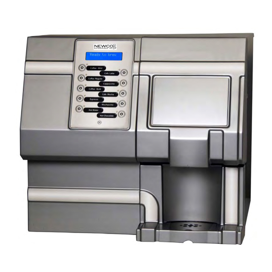
Page 5: Machine Dimensions & Specifications
Machine Dimensions & Specifications 120 VAC-1700W HEATER-15A USA POWER SUPPLY 1 GALLON TANK 8-12 OZ CUP SIZE TEMPERATURE RANGE 180-205F Machine Functions Product Brewing Door Selection Switch & Display Coffee POD Chocolate & Latte Waste Drawer Ingredient Cabinet Water Inlet Drip Tray &... - Page 6 Machine Dimensions & Specifications – Continued FRONT VIEW Powder Hoppers RINSE Rinse Button Whipping Chamber Coffee POD Waste Drawer Overflow Drip Tray...
-
Page 7: Machine Features
Machine Features • AUTOMATED POD BREW DRAWER • FACTORY CALIBRATED-PLUG & PLAY • WHIPPER RINSE BUTTON • AUTOMATIC POWDER LEVEL RESET OPTION • POD DRAWER COUNT & COUNT RESET • 88 PRE-PROGRAMMED DRINK RECIPES • BUTTON ASSIGNMENT FOR RECIPES • INDEPENDENT POWDER HOPPER COUNTDOWN &... -
Page 8: Plumbing Connections
25 feet from the 1/2” water supply line. A tight coil of copper tubing in the water line will facilitate moving the machine to clean the counter top. Newco does not recommend the use of a saddle valve to install the brewer. -
Page 9: Installation Instructions
Installation Instructions WARNING: - Read and follow installation instructions before plugging or wiring in machine to electrical circuit. Warranty will be void if machine is connected to any voltage other than that specified on the nameplate serial tag. Machine must be on a flat and level surface. Plug or wire in machine to appropriate voltage as noted on the brewer serial tag. -
Page 10: Set-Up Instructions
Set up instructions for CX3 Machine Fill and install 2lb hoppers with nozzles turned up, Chocolate on left and Milk on right. Make sure “button” on bottom of hopper is seated in slot in sheet metal. Slight manual rotation of the auger gear may be necessary to seat hopper in correct location. Rotate dispense nozzles down into whipper bowl. -
Page 11: Programming Instructions
Programming Instructions To enter into “Programming Mode”, hold the BOTTOM CENTER button while powering up the machine with the power switch. Select Menu The machine readout will display in the Message Display Area. Maintenance Maintenance, Statistics, and Machine Setup Modes are accessible in the Programming Mode. The following applies to screen navigation in this mode: 1) Upper 2 left buttons are for entering a menu or adjusting the parameter. - Page 12 Programming Instructions (Cont’d) Pressing the “COFFEE-MILD” Button will select the Mode Displayed Pressing the “LATTE” Button will scroll forward through the Select Menu Choices Pressing the “CAPPUCCINO” Button will scroll backwards through the Select Menu Choices Pressing the “LATTE” button repeatedly will loop the display in 4 Modes: Maintenance---Statistics---Setup--- ---Exit Program Mode Maintenance 1.
- Page 13 Programming-Cont’d Setup 1. Press Button to Select “Setup” 2. Press Button to Toggle display 3. Use to Change Values Up Or Down Water Temperature Setting (170-205 F) Buzzer volume 0-24 Filter size 500 1000 1500 2000 2500 3000 (OFF)GAL Energy Save (Off, Semi [180F], Full [0FF] Assign Recipes To Buttons * Call for service # (Re-settable phone Number) * Powder Tracking (On, Off)
- Page 14 Programming-Cont’d Assigning Recipes To Buttons 1. Press Button to Select “Setup”. 2. Toggle Selection to “Assign Recipes”. 3. Select “Assign Recipes”. 4. Scroll Up & Down “Recipe Choices” With These Two (2) Buttons. Select “Recipe” To Be Assigned a Button. 5.
- Page 15 Programming-Cont’d Changing “Call For Service” Number (Only when “On”) Note: Whenever the machine detects a service problem, a description of the problem and a “Call for Service” Telephone Number Scrolls across the Display. This number can be changed during machine Set-Up. Select the “Call for Service #”...
- Page 16 Programming-Cont’d Selecting “Powder Tracking “ Option Note: This option enables or disables Powder tracking for drinks using powdered chocolate or powdered milk. The machine can keep track of how much powder is left in the powder canister and suggest that the canister be refilled when nearly empty.
-
Page 17: Service Notes & Troubleshooting
Service Notes & Troubleshooting MACHINE CALIBRATION NOTE: THIS MACHINE HAS BEEN CALIBRATED AT THE FACTORY, AND CHANGING THESE SETTINGS CAN AFFECT THE QUALITY OF THE DRINK. ANY CHANGE TO THESE SETTINGS MUST BE DONE BY TRAINED SERVICE PERSONELL ONLY. To Access Calibration Menu: Hold Lower LH Button Down While Turning Machine Power On CALIBRATION... - Page 18 CALIBRATION NOTES & INSTRUCTIONS- CONT’D “Bypass Speed”, this is the pump duty cycle value, 1-10, to adjust the “Hot water Bypass”, or hot water speed during machine cycles. Note: too high a value may result in water overflow, too low a value and water will trickle out of machine. Value is set at 4 at the factory.
- Page 19 CALIBRATION NOTES & INSTRUCTIONS- CONT’D Auger 1: “Left Auger Speed (Chocolate)”, this is the left or chocolate auger delivery duty cycle value, 1-10, to adjust the auger motor speed for delivering powdered product. This value should remain at 9 or 10 for the Wolfgang Puck powdered products. Value is set at 9 at the factory.
- Page 20 Service Notes This machine uses advanced diagnostics to alert the operator should any of the motors or motor controllers sense the motors are not turning at the correct rate or sense a bad connection. These errors highlighted by a scrolling display such as “Call for Service—(Left Auger) Motor Error”, and the Service Number entered during machine set-up will be displayed.
-
Page 21: Machine Access Points
Machine Access Points Top Cover Brew Mech Access Tank Access Main Rear Cover Tank, Pump Access, Sidecar Cover Transformer, Fill Valve Control Board Access... -
Page 22: Pod Brew Mechanism Removal
Pod Brew Mechanism Removal Front View From Drip Tray 1. Remove (2) Outer Brass Nuts Save for Re-Assembly Front View - Cover Off 3. Unsnap Water Fitting: Pull out Water fitting 4. Unsnap Wiring Harness-Lift Brew Mech Up and Out of Machine... -
Page 23: Whipper Assembly
Whipper Assembly PN 767377 ITEM # PART NUMBER & DESCRIPTION 767376 WHIPPER STEAM CAP 767195 WHIPPER MOTOR 767196 BASE, WHIPPER MOUNTING 767390,O-RING WHIPPER BASE RED [NOT SHOWN] 767197 WHIPPER IMPELLER 767365 WHIPPER BOWL 767200 WHIPPER NOZZLE 781566 WHIPPER SEAL (REPLACE AFTER 5000 CYCLES) - Page 24 Tank Assembly PN 780048 ITEM # PART NUMBER DESCRIPTION QTY/EA 110958 RELAY, 12 VDC SPST 30A 111593 HI-LIMIT THERMOSTAT 109937 GEAR PUMP ASS’Y 781772 PUMP ASS’Y W/ELBOW (HOT WATER) 780253 TANK ONLY 773056 AIR PUMP, POD 500396 LIQUID LEVEL PROBE& BUSHING 151677 DUAL TEMP THERM PROBE 100149...
- Page 25 Whipper Cannister Assembly (767377) & (767385 & 767386) ITEM # PART NUMBER & DESCRIPTION 780796-HOPPER ASS’Y, RH (LATTE) 767202-ELBOW, 7CM,RH 767376-WHIPPER CAP 767365-BOWL, WHIPPER, 767197-IMPELLER 767196-WHIPPER BASE, 767195- MOTOR 767200-NOZZLE, WHIPPER 781040-BULKHEAD, WATER (NOT SHOWN) 767201-ELBOW, 7CM,LH 780197-HOPPER ASS’Y, LH (CHOCOLATE) 780153 -HOPPER LID-BROWN 780154-HOPPER LID-WHITE...
- Page 26 LOWER BREW CHAMBER O-RING NOTE: Your CX-3 can be equipped with various optional brew mechanisms to provide brewing choices tailored to your specific needs. For information on these optional brew mechanisms and associated replacement parts contact NEWCO Technical Services at...
Need help?
Do you have a question about the CX-3 and is the answer not in the manual?
Questions and answers