Chapters
Table of Contents

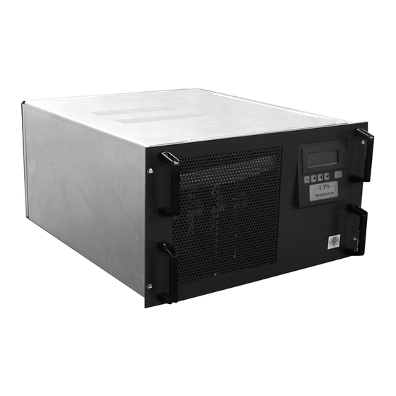
Related Manuals for Meta System MEGALINE 1250 RACK

Summary of Contents for Meta System MEGALINE 1250 RACK
- Page 1 MEGALINE RACK GRUPPO DI CONTINUITA’ UNINTERRUPTIBLE POWER SUPPLY UNTERBRECHUNGSFREIE STROMVERSORGUNGSEINHEIT Manuale d’uso per l’utente - Instruction manual Bedienungsanleitung www.metasystem.it...
- Page 2 Majakovskij, 10/b Reggio Emilia, Italia Tipo di apparecchiatura: Gruppo di Continuità Modelli: MEGALINE 1250 RACK - MEGALINE 2500 RACK MEGALINE 3750 RACK - MEGALINE 5000 RACK Anno di apposizione del marchio: 2004 L’apparecchiatura è stata provata nella configurazione tipica di installazione e con periferiche conformi alle direttive sopra elencate.
-
Page 3: Table Of Contents
Indice Indice 1 - Introduzione Avvertenze 2 - Funzionamento Principio di Funzionamento Funzionamento a rete Funzionamento a batteria Funzionamento a By-pass Informazioni sul display Segnalazioni ottiche e acustiche 3 - Installazione Predisposizione all’installazione Collocazione del Gruppo di Continuità Pannello Frontale Procedura d’installazione singolo cabinet Predisposizione per espansione autonomia Guida all’uso del software autodiagnostico... -
Page 4: Introduzione
Introduzione Vi ringraziamo per l’acquisto di un prodotto MetaSystem. Obiettivo primario della nostra Azienda è di fornire sempre prodotti all’avanguardia, frutto della ricerca e dell’applicazione delle tecnologie più innovative. Le nostre apparecchiature sono coperte da numerosi brevetti internazionali, rappresentativi del carattere di esclusività... -
Page 5: Funzionamento
2 - Funzionamento 2. Funzionamento Schema a blocchi USCITA BY PASS FILTRO DI USCITA INGRESSO INVERTER REGOLATORE FILTRO DEL FATTORE D’INGRESSO DI POTENZA MODULO DI POTENZA SURVOLTORE BATTERIE CARICA BATTERIE MODULO DI POTENZA BATTERIE LOGICA INTERFACCIA A MICRO- RS 232 PROCESSORE COMANDO DISTANZA... -
Page 6: Funzionamento A Rete
2 - Funzionamento La combinazione di queste segnalazioni rende rapida e intuitiva l’individuazione dello stato di funzionamento e di eventuali problemi alla rete di alimentazione. Sono possibili tre principali modi di funzionamento - Funzionamento a rete - Funzionamento a batteria - Funzionamento in By-pass Funzionamento a rete E’... -
Page 7: Segnalazioni Ottiche E Acustiche
2 - Funzionamento Segnalazioni ottiche e acustiche INDICATORE SEGNALATORE MESSAGGI DESCRIZIONE DI STATO ACUSTICO A DISPLAY - - - UPS a Rete Funzionamento normale con rete Verde IN xxxV/x.xkW presente e carico entro i limiti UPS a Rete Il gruppo di continuità segnala che la Verde - - - frequenza della tensione di uscita non è... -
Page 8: Installazione
3 - Installazione 3. Installazione Predisposizione all’installazione Verificare che l’imballo sia integro e che il prodotto non abbia subito danni durante il trasporto. In caso di problemi contattare il vettore. Verificare il contenuto della confezione: • Nr.1 gruppo di continuità •... -
Page 9: Pannello Frontale
3 - Installazione Pannello frontale 1 Display alfanumerico 2 Tasto ESC / uscita da funzioni / tacitazione segnalatore acustico 3 Tasto scorrimento precedente / aumenta valore 4 Tasto scorrimento successivo / diminuisci valore 5 Tasto invio / accettazione funzioni / accesso menu 6 Tasto di accensione / spegnimento 7 Indicatore stato di funzionamento multicolore (verde / giallo / rosso) Procedura d’installazione... - Page 10 3 - Installazione Singolo cabinet Cablare il connettore di Ingresso-Uscita in dotazione come CONNETTORE DI INGRESSO-USCITA indicato in figura 2, utilizzando un cavo inguainato con Assemblaggio conduttori interni aventi sezione di almeno 2,5 mm Inserire il connettore nel coperchio in plastica fissandolo con le apposite viti, quindi assicurare i cavi al coperchio tramite il fermacavo (vedi fig.
-
Page 11: Predisposizione Per Espansione Autonomia
3 - Installazione Predisposizione per espansione Autonomia L’UPS è dotato della predisposizione al collegamento di unità batterie aggiuntive: per collegare uno o più cabinet aggiuntivi all’unità singola procedere nel seguente modo: Svitare le viti in figura 5 . Spostare il coperchio di protezione fino a scoprire completamente i connettori posti all’interno della finestra. -
Page 12: Personalizzazione Delle Modalità Di Funzionamento
4 - Personalizzazione delle modalità di funzionamento 4. Personalizzazione delle modalità di funzionamento Funzioni dei tasti L’accesso ai menu del gruppo di continuità avviene mediante i tasti posti sul pannello frontale TASTO DESCRIZIONE - Uscita da una funzione senza modificare - Passaggio da un livello di menu inferiore a uno superiore - Uscita dal menu principale e ritorno alla visualizzazione dello stato - Tacitazione del segnalatore acustico... -
Page 13: Stato Ups
4 - Personalizzazione delle modalità di funzionamento MENU PRINCIPALE Stato UPS Config. UPS Eventi Programmazione Strumenti STATO UPS Config. UPS Eventi Programmazione Strumenti Calendario Progr. Info UPS Uscita Test Segnalazioni Visualizzazione Riaccensione Uscita Ingresso Test Display LCD Cancellazione Spegnimento Ingresso Bypass Test Batterie Batterie... - Page 14 4 - Personalizzazione delle modalità di funzionamento Ingresso Potenza Indica il valore della potenza assorbita dalla rete (W) Potenza xxxx Pot.Appar. Indica il valore della potenza apparente assorbita dalla rete (VA) Pot.Appar. xxxx Indica il valore della tensione efficace (V RMS) in ingresso V eff.
-
Page 15: Configurazione Ups
4 - Personalizzazione delle modalità di funzionamento Misc. ➧ Indica la temperatura interna al gruppo di continuità Temp.interna Temp.interna espressa in gradi centigradi Temp.esterna Indica la temperatura esterna al gruppo di continuità Temp. esterna Vel.ventole espressa in gradi centigradi Vel.Ventole Indica la velocità... - Page 16 4 - Personalizzazione delle modalità di funzionamento Ingresso ➧ Se abilitato, il gruppo di continuità sincronizza la sinusoide Abilitazione Abilitazione PLL di uscita con l’ingresso. Range PLL esteso Se disabilitato la tensione di uscita non è sincronizzata con l’ingresso e viene segnalato con il lampeggio dell’indicatore di stato (verde) Se abilitato, il gruppo di continuità...
- Page 17 4 - Personalizzazione delle modalità di funzionamento ATTENZIONE! La programmazione segue la seguente priorità:. Abilitazione Funzione attiva Modo forzato Modo off-line Attesa carico By-pass MODO FORZATO ABILITATO ABILITATO MODO OFF-LINE ABILITATO ABILITATO ABILITATO DISABILITATO MODO OFF-LINE ABILITATO ABILITATO DISABILITATO DISABILITATO ABILITATO DISABILITATO ABILITATO...
- Page 18 4 - Personalizzazione delle modalità di funzionamento AVANZATA Batterie ➧ Gestione Avanzata Gestione capacità capacità Preavviso Fine Aut Preavviso Impostazione del preavviso di fine autonomia Fine Aut batterie espresso come tempo di funzionamento rimanente (minuti) SEMPLICE Batterie ➧ Gestione Semplice Gestione capacità...
-
Page 19: Eventi
4 - Personalizzazione delle modalità di funzionamento Batterie Max tempo Impostazione del tempo massimo di funzionamento Max. tempo Batteria Batteria continuativo nella modalità BATTERIA espresso in secondi. ➧ Max. tempo riserva Impostando “0” la funzione è disabilitata. Abilit.test Accens Max tempo Impostazione del tempo massimo di funzionamento nella Abilit. -
Page 20: Programmazione
4 - Personalizzazione delle modalità di funzionamento Programmazione Calendario Prog. Abilitazione Esegue l’abilitazione o la disabilitazione dei programmi inseriti ➧ Abilitazione Visual./Modifica Consente l’inserimento e la modifica programmi. Sono Visual./Modifica disponibili le seguenti funzioni: Sequenza progr. Test Batterie (verifica stato batterie) Cancellazione Calibrazione Batt.(calibrazione batterie) Turn on (accensione del gruppo di continuita) -
Page 21: Caratteristiche Tecniche
5 - Caratteristiche tecniche 5. Caratteristiche Tecniche Specifiche Costruttive MEGALINE MEGALINE MEGALINE MEGALINE 1250 2500 3750 5000 Pesi (Kg.) 23,5 Dimensioni Rack 19” 6U 483,5 X 266 (6U) X 600 (LxHxP) Tecnologia PWM ad alta frequenza sia per lo stadio di ingresso che per quello di uscita. Logica di controllo a microprocessore Espandibilità... -
Page 22: Caratteristiche Elettriche D'ingresso
5 - Caratteristiche tecniche Caratteristiche Elettriche d’ Ingresso MEGALINE MEGALINE MEGALINE MEGALINE 5000 1250 2500 3750 Tensioni nominali 230 V d’ingresso Gamma tensione da 184V a 264V con carico nom. - da 100V a 264V al 50% del carico nom. ingresso Frequenza 50 Hz o 60 Hz +2% (autosensing e/o selezionabile dall’utente) -
Page 23: Caratteristiche Elettriche Di Uscita In Funzionamento A Rete
5 - Caratteristiche tecniche Caratteristiche Elettriche di Uscita in Funzionamento a Rete MEGALINE MEGALINE MEGALINE MEGALINE 1250 3750 5000 2500 Tensione nominale 230 V ± 1% d’uscita Frequenza 50 Hz / 60Hz sincronizzata (autosensing e/o selezionabile dall’utente) nominale d’uscita Corrente d’uscita su carico lineare fattore 10,75A rms 21,6A rms... -
Page 24: Caratteristiche Elettriche Di Uscita In Funzionamento A Batteria
5 - Caratteristiche tecniche Caratteristiche Elettriche di Uscita in Funzionamento a Batteria MEGALINE MEGALINE MEGALINE MEGALINE 5000 3750 1250 2500 Tensione nominale 230 V ± 1% d’uscita Frequenza 50 Hz / 60Hz ± 1% (autosensing e/o selezionabile dall’utente) d’uscita Potenza nominale 2500VA 1250VA 3750VA... -
Page 25: Funzionamento A Batteria
5 - Caratteristiche tecniche Funzionamento a Batteria MEGALINE MEGALINE MEGALINE MEGALINE 1250 3750 5000 2500 Autonomia indicativa in minuti con batterie cariche Carico applicato in 100% 100% 100% 100% percentuale UPS Standard Tempo di ricarica fino al 90% della 5 - 6 ore a seconda del livello di scarica raggiunto carica totale Dati tecnici e n. -
Page 26: Normative Di Riferimento
5 - Caratteristiche tecniche Normative di riferimento MEGALINE MEGALINE MEGALINE MEGALINE 1250 2500 3750 5000 Sicurezza: progettato per Rispondente alla normativa EN 62040-1-1 soddisfare la norma Compatibilità elettromagnetica: Rispondente alla normativa EN 50091-2 (classe A) •immunità Rispondente alla normativa EN 50091-2 (classe B) •emissioni Prestazioni... -
Page 27: Soluzione Ai Problemi
6 - Soluzione ai problemi 6. Soluzione ai problemi Problemi Soluzioni È errato il collegamento del conduttore di neutro: All’accensione l’UPS fa suonare il cicalino e girare la spina di alimentazione, oppure invertire il lampeggiare il segnalatore visivo rosso con intermittenza di tipo alternato breve-lungo, quindi senso di collegamento dei cavi di neutro e fase di ingresso, oppure escludere sensore di neutro. - Page 28 Majakovskij, 10/b Reggio Emilia, Italy Type of appliance: Uninterruptible Power Supply Models: MEGALINE 1250 RACK - MEGALINE 2500 RACK MEGALINE 3750 RACK - MEGALINE 5000 RACK Year of application of the mark: 2004 The appliance was tested in the typical configuration for its installation and with peripherals in compliance with the above Directives.
- Page 29 Index Index 1 - Introduction Important information 2 - Operation Operating principle Mains operation Battery operation By-pass operation Information provided by the display Visual and acoustic warning signals 3 - Installation Prior to installation Where to install your UPS Front panel Installation procedure for a single cabinet UPS Presetting for the expansion of autonomy Guide to using the diagnostics software...
- Page 30 Introduction Thank you for choosing to purchase a MetaSystem product. Our company’s main objective is to supply innovative products that are the outcome of our ongoing research and application of cutting-edge technology. Our products are covered by several international patents, emblematic of MetaSystem’s quest for exclusivity and ongoing improvement.
- Page 31 2 - Operation 2. Operation Block diagram O U T P U T BY PASS OUTPUT FILTER INPUT POWER INPUT INVERTER FACTOR FILTER CORRECTOR POWER MODULE VOLTAGE BOOSTER BATTERIES BATTERY CHARGER POWER MODULE BATTERIES MICRO- RS 232 PROCESSOR INTERFACE LOGIC REMOTE CONTROL Operating principle...
- Page 32 2 - Operation The combination of these signals enables rapid and intuitive understanding of its operating status and recognition of any problems in the power supply. There are three main operating modes - Mains operation - Battery operation - By-pass operation Mains operation This is considered the normal operating condition: - mains voltage is converted by the power factor corrector (PFC) into continuous current...
- Page 33 2 - Operation Visual and acoustic warning signals STATUS ACOUSTIC MESSAGES DESCRIPTION INDICATOR SIGNAL DISPLAYED - - - UPS on Mains Normal operation with mains present and Green IN xxxV loads within the set limits UPS on Mains Green - - - The UPS is indicating that the frequency of No sync mains the output voltage is not synchronised with...
- Page 34 3 - Installation 3. Installation Prior to installation Check the packaging has not been opened or damaged and that the product has not been damaged during transport. Please contact your shipping agent in case of doubt. Check the contents of the box: •...
- Page 35 3 - Installation Front panel 1 Alphanumeric Display 2 ESC button / exit function / silence acoustic signal 3 Button to scroll backwards / increase value 4 Button to scroll forwards / decrease value 5 Enter button / confirm function / access menu 6 Button to switch on / switch off 7 Multicolour operating status indicator light (green / yellow / red) Installation procedure for a single cabinet UPS...
- Page 36 3 - Installation Single cabinet Wire up the Input-Output connector supplied as shown in INPUT-OUTPUT CONNECTOR figure 3, using insulated cable with wires whose section is at Assembly least 2.5 mm2. Insert the connector into the plastic housing and secure it using the screws supplied.
- Page 37 3 - Installation Presetting for the expansion of autonomy Your UPS is complete with presetting for the connection of additional battery cabinets. One or more extra battery cabinets can be fitted to a single cabinet UPS as follows: Unscrew screws shown in figure 5.
- Page 38 4 - Customising the UPS operating mode 4. Customising the UPS operating mode The functions of the buttons The buttons on the front panel of the UPS are used to access its various menus BUTTON DESCRIPTION - Exit a function without modifying it - Go up a level to an upper level menu - Exit the main menu and return to status display - Silence the buzzer...
- Page 39 4 - Customising the UPS operating mode MAIN MENU UPS Status UPS Config. Events Programming Tools UPS STATUS UPS Setup Events Scheduling Tools UPS Info Output log View Signalling Test Schedule Planning Output Input log Reset LCD Display Test Restart Input Bypass Battery Test...
- Page 40 4 - Customising the UPS operating mode Input Power Indicates the power received from mains (W) Power xxxx Appar. Pow. Indicates the apparent power received from mains (VA) Appar.Pow. xxxx V RMS ➧ V RMS Indicates the effective voltage (V RMS) at the UPS input I RMS xxxx Indicates the effective current (A RMS) received from...
- Page 41 4 - Customising the UPS operating mode Misc. ➧ Indicates the internal temperature of the UPS, shown in Int. Temp. Int. Temp. Celsius Ext. Temp. Indicates the external temperature of the UPS, shown in Ext. Temp. Fan speed Celsius Fan speed Indicates the speed of the UPS cooling fans, shown in a percentage format (100% = maximum speed) UPS Setup...
- Page 42 4 - Customising the UPS operating mode Input ➧ If enabled, the UPS synchronises the output sine wave PLL Enable with the input PLL Enable If disabled, the output voltage is not synchronised with the Extended PLL Range input. This is indicated by the flashing of the status warning light (green) If enabled, the UPS synchronises the output voltage with Extended...
- Page 43 4 - Customising the UPS operating mode ATTENTION! Programming priority is as follows: Enable Operational function Load Waiting Forced Mode Off-line mode By-pass FORCED MODE ENABLED ENABLED OFF-LINE MODE ENABLED ENABLED ENABLED DISABLED OFF-LINE MODE ENABLED ENABLED DISABLED DISABLED ENABLED DISABLED ENABLED DISABLED...
- Page 44 4 - Customising the UPS operating mode ADVANCED MODE Batteries ➧ Set capacity Advanced mode Set capacity Reserve Time Reserve Sets the warning signal for the end of battery Time autonomy using the remaining run time (minutes) SIMPLE MODE Batteries ➧...
- Page 45 4 - Customising the UPS operating mode Batteries Max Time On Sets the maximum time for continuous operation in Max Time On Batt. Batt. BATTERY mode, shown in seconds. If “0” is set, this ➧ Max time reserve function is disabled. TurnOn Test Enable Max time Sets the maximum time for operation in BATTERY mode...
- Page 46 4 - Customising the UPS operating mode Programming Planning Schedule Enable To enable or disable set programmes ➧ Enable View/Edit To set and modify programmes. The following functions are View/Edit available: Sched. sequence - Batteries Test (verifies the status of the batteries) Reset - Batt.
- Page 47 5 - Specifications 5. Specifications Construction specifications MEGALINE MEGALINE MEGALINE MEGALINE 2500 3750 5000 1250 Weight (Kg.) 23,5 Size Rack 19” 6U 483,5 X 266 (6U) X 600 (LxHxP) Technology PWM high frequency both for input stage and output stage. Microprocessor control logic Expandability Optional upgrading to configurations with higher power by fitting one or more extra power modules inside the same cabinet, up to a maximum of 4.
- Page 48 5 - Specifications Electrical input specifications MEGALINE MEGALINE MEGALINE MEGALINE 3750 2500 5000 1250 Nominal input 230 V voltage Input voltage from 184V to 264V with nom. load – from 100V to 264V with 50% of nom. load range Nominal input 50 Hz or 60 Hz +/-2% (autosensing and/or as selected by operator) frequency Nominal input...
- Page 49 5 - Specifications Electrical output specifications when running on mains power MEGALINE MEGALINE MEGALINE MEGALINE 2500 3750 5000 1250 Nominal output 230 V ± 1% voltage Nominal output 50 Hz / 60Hz synchronised (autosensing and/or as selected by operator) frequency Output current with linear load and 5,37A rms...
- Page 50 5 - Specification Electrical output specifications when running on battery power MEGALINE MEGALINE MEGALINE MEGALINE 1250 2500 3750 5000 Nominal output 230 V ± 1% voltage Output 50 Hz / 60Hz ± 1% (autosensing and/or as selected by operator) frequency Nominal output 1250 VA 2500 VA...
-
Page 51: Battery Operation
5 - Specification Battery operation MEGALINE MEGALINE MEGALINE MEGALINE 5000 1250 3750 2500 Approximate autonomy in minutes with charged batteries Percentage of 100% 100% 100% 100% applied load Standard UPS Recharge time up to 5 - 6 hours according to level of discharge 90% of total charge Specifications and n. - Page 52 5 - Specifications Reference Standards MEGALINE MEGALINE MEGALINE MEGALINE 1250 2500 3750 5000 Safety: Conforms to standard EN 62040-1-1 Designed to satisfy standard Electromagnetic compatibility: Conforms to standard EN 50091-2 (class A) •immunity Conforms to standard EN 50091-2 (class B) •emission Typical Conforms to standard EN 62040-3...
-
Page 53: Troubleshooting
6 - Troubleshooting Guide 6. Troubleshooting Problems Solutions The connection of the neutral conductor is wrong: When the UPS is switched on, the buzzer sounds and the red warning light makes alternating invert the power supply plug, or invert the short-long flashes, then the UPS switches off connections of the neutral and phase input leads, or exclude the neutral sensor. - Page 54 Majakovskij 10/b, Reggio Emilia, Italien Gerätetyp: Unterbrechungsfreie Stromversorgungseinheit Modelle: MEGALINE 1250 RACK - MEGALINE 2500 RACK MEGALINE 3750 RACK - MEGALINE 5000 RACK 2004 Jahr der Anbringung des Prüfzeichens: Das Gerät wurde in der typischen Installationskonfiguration und mit Periphereinrichtungen geprüft, die den o.g. Richlinien entsprechen.
- Page 55 Inhaltsverzeichnis Inhaltsverzeichnis 1 - Einführung ................Sicherheitshinweise ..............56 2 - Betrieb ................Funktionsprinzip..............57 Netzbetrieb ................58 Batteriebetrieb................58 Bypassbetrieb ................58 Informationen auf dem Display ..........58 Optische und akustische Anzeigen ..........59 3 - Installation ................Vorbereitung der Installation ............60 Aufstellen der USV-Einheit ............60 Bedienfront ................61 Installation einer einzelnen Einheit ..........61 Vorbereitung für die Verlängerung der Autonomiezeit ....63...
-
Page 56: Einführung
Einführung Wir danken Ihnen, dass Sie sich für ein Produkt von MetaSystem entschieden haben. Unser Unternehmen hat es sich zum Ziel gesetzt, stets absolut moderne Produkte anzubieten, die das Ergebnis intensiver Forschung und der Anwendung der innovativsten Technologien sind. Unsere Geräte sind durch zahlreiche internationale Patente geschützt, die das große Engagement von MetaSystem zugunsten der kontinuierlichen Produktverbesserung beweisen. -
Page 57: Betrieb
2 - Betrieb 2. Betrieb Blockschaltbild AUSGANG BY PASS AUSGANGSFILTER EINGANG WECHSELRICHTER EINGANGSFILTER LEISTUNGSFAKTOR REGLER LEISTUNGS MODUL SPANNUNGS BATTERIEN VERSTÄRKER BATTERIE LADEGERÄT LEISTUNGSMODUL BATTERIE LOGIK MIT SCHNITTSTELLE MIKRO- RS 232 PROZESSOR COMANDO FERNSTELLERUNG DISTANZA Funktionsprinzip Beim Vorliegen der Netzspannung wird die Eingangsspannung von einer speziellen Eingangsstufe (Leistungs- faktorregler) gefiltert und gleichgerichtet, um einerseits die Stromaufnahme vom Netz zu optimieren, indem der Leistungsfaktor fast auf 1 gebracht wird, und andererseits Spannungsschwankungen auszugleichen. -
Page 58: Netzbetrieb
2 - Betrieb Die Kombination dieser Anzeigen erlaubt die rasche und intuitive Erkennung des Betriebszustands und eventueller Störungen im Versorgungsnetz. Es gibt drei Hauptbetriebsarten: - Netzbetrieb - Batteriebetrieb - Bypassbetrieb Netzbetrieb Dies ist der normale Betriebszustand: - Die Netzspannung wird vom Leistungsfaktorregler (PFC) in Gleichspannung umgewandelt. - Der Wechselrichter erzeugt aus der Gleichspannung wieder eine Sinusspannung. -
Page 59: Optische Und Akustische Anzeigen
2 - Betrieb Optische und akustische Anzeigen ZUSTANDS- AKUSTISCHER MELDUNGEN BESCHREIBUNG ANZEIGE SIGNALGEBER AUF DEM DISPLAY - - - Netzbetrieb Normalbetrieb beim Vorliegen der Netzspannung Grün IN xxxV und Last innerhalb der zulässigen Grenzen. Netzbetrieb Die USV-Einheit signalisiert, dass die Frequenz Grün - - - der Ausgangsspannung nicht mit der der... -
Page 60: Installation
3 - Installation 3. Installation Vorbereitung der Installation Sicherstellen, dass die Verpackung unversehrt ist und dass das Gerät nicht beim Transport beschädigt wurde. Bei Problemen den Spediteur kontaktieren. Den Inhalt der Verpackung überprüfen: • 1 Unterbrechungsfreie Stromversorgungseinheit • 1 Steckverbinder für die Verkabelung IN/OUT (Version Einzelgerät einschließlich Mehrfachsteckdose und Eingangskabel) •... -
Page 61: Bedienfront
3 - Installation Bedienfront Alphanumerisches Display Taste ESC (Verlassen von Funktionen / Stummschalten des akustischen Signalgebers) Pfeiltaste auf (zurückrollen / Werte erhöhen) Pfeiltaste ab (vorrollen / Werte herabsetzen) Eingabe-Taste (Annahme von Funktionen / Aufrufen von Menüs) Taste Einschalten / Ausschalten Mehrfarbige Zustandsanzeige (grün / gelb / rot) Installation einer einzelnen Einheit Elektrische Anschlüsse... - Page 62 3 - Installation Einzelne Einheit Den beiliegenden Steckverbinder Eingang-Ausgang wie in Abbildung 2 gezeigt verdrahten; hierzu ummantelte Kabel verwenden, deren Leiter einen Mindestquerschnitt von 2,5 mm haben. Die Klemmenplatte in den Kunststoffdeckel einsetzen und mit den zugehörigen Schrauben befestigen. Dann die Kabel mit der Zugentlastung am Deckel sichern (siehe Abb.
-
Page 63: Vorbereitung Für Die Verlängerung Der Autonomiezeit
3 - Installation Vorbereitung für die Verlängerung der Autonomiezeit Die USV-Einheit verfügt über eine Vorrüstung für den Anschluss zusätzlicher Batterieeinheiten: Zum Anschließen von einer oder mehreren zusätzlichen Einheiten an das Einzelgerät wie folgt vorgehen: Die Schrauben (siehe Abb. 5) abschrauben. Die Schutzabdeckung schieben, um auf die Steckverbinder im Innern des Ausschnitts zugreifen zu können. -
Page 64: Anpassung Der Betriebsarten
4 - Anpassung der Betriebsarten 4. Anpassung der Betriebsarten Funktionen der Tasten Der Zugriff auf die Menüs der USV-Einheit erfolgt mit den Tasten auf der Bedienfront. TASTE BESCHREIBUNG - Verlassen einer Funktion ohne Speichern der Änderungen - Wechseln von einer Menüebene zu einer höheren Ebene - Verlassen des Hauptmenüs und Rückkehr zur Zustandsanzeige - Stummschalten des akustischen Signalgebers - Wahl der vorherigen Funktion... -
Page 65: Zustand Der Usv-Einheit
4 - Anpassung der Betriebsarten HAUPTMENÜ USV-Status USV-Setup Ereignisse Zeitprogramm Test/Kalib. ZUSTAND USV Konfig. USV Ereignisse Programmierung Testfunktionen Ausgang Kalender Progr. USV-Info Anzeigentest Anzeigen Eingang Wiedereinschalten Ausgang Test LCD-Display Löschen Bypass Ausschalten Eingang Batterientest Sensor Batterie Batt. kalibrieren Neutralleiter Ereignisse Batterien Allgemein Einst. - Page 66 4 - Anpassung der Betriebsarten Eingang Leistung Leistungsaufnahme vom Netz (W) Leistung xxxx Scheinleistung Scheinleistungsaufnahme vom Netz (VA) Scheinleistung xxxx Ist-Wert der Spannung (V RMS) am Eingang der USV-Einheit ➧ V RMS V RMS I RMS xxxx Ist-Wert der Stromaufnahme vom Netz (A RMS) I RMS I Peak Frequenz...
-
Page 67: Konfiguration Der Usv-Einheit
4 - Anpassung der Betriebsarten Allgemein ➧ Temperatur innerhalb der USV-Einheit in °C Int. Temp. Int. Temp. Ext, Temp. Temperatur außerhalb der USV-Einheit in °C Ext. Temp. Lüfter Geschw. Lüfter Drehzahl der Lüfter der USV-Einheit in Prozent (100% = maximale Drehzahl) Geschw. - Page 68 4 - Anpassung der Betriebsarten Eingang ➧ Bei Aktivierung dieser Option synchronisiert die USV- PLL Aktiv PLL Aktiv Einheit die Sinuswelle am Ausgang mit dem Eingang; ist die Option deaktiviert, ist die Ausgangsspannung nicht Erweiterter PLL mit dem Eingang synchronisiert, was durch das Blinken der Zustandsanzeige (grün) signalisiert wird Erweiterter Bei Aktivierung dieser Option synchronisiert die USV-Einheit die...
- Page 69 4 - Anpassung der Betriebsarten ACHTUNG! Die Programmierung erfolgt nach den folgenden Prioritäten: Aktiver Aktivierung Zwangsbetrieb Offline-Modus Lasterkennung Betriebsmodus Bypass ZWANGSBETRIEB AKTIVIERT AKTIVIERT OFFLINE-MODUS AKTIVIERT AKTIVIERT AKTIVIERT DEAKTIVIERT OFFLINE-MODUS AKTIVIERT AKTIVIERT DEAKTIVIERT DEAKTIVIERT AKTIVIERT DEAKTIVIERT AKTIVIERT DEAKTIVIERT MODUS LASTERKENNUNG AKTIVIERT DEAKTIVIERT DEAKTIVIERT DEAKTIVIERT...
- Page 70 4 - Anpassung der Betriebsarten ERWEITERT Batterie ➧ Kapaz- Erzweitert Kapaz-management management Reservezeit Reservezeit Einstellung der Vorwarnung für das Ende der Batterienautonomiezeit als verbleibende Betriebszeit (in Minuten) NORMAL Batterie ➧ Kapaz- Normal Kapaz-management management Batt.-schwellen Batt.- Einstellung der Vorwarnung für das Ende der schwellen Autonomiezeit als Wert der Batteriespannung Das Menü...
-
Page 71: Ereignisse
4 - Anpassung der Betriebsarten Batterien Max. Einstellung der maximalen Dauerbetriebszeit in Sekunden Max. Batteriezeit Batteriezeit im Batteriebetrieb ➧ Gibt man “0” ein, wird die Funktion deaktiviert Max. Reservezeit Test beim Einsch-aktiv Max. Einstellung der maximalen Betriebszeit in Sekunden im Autostart aktiv Batteriebetrieb nach Erreichen der Reserve Reservezeit... -
Page 72: Testfunktionen
4 - Anpassung der Betriebsarten Zeitprogramm Zeitplan Aktiv Zum Aktivieren oder Deaktivieren der eingegebenen Programme ➧ Aktiv Erlaubt die Eingabe und das Ändern der Programme Bearbeiten Bearbeiten Folgende Funktionen sind verfügbar: Sequenz Batterientest (Zustandskontrolle der Batterien) Reset Batt.kalibrieren(Kalibration der Batterien) Einschaltung (Einschalten der USV-Einheit) Ausschaltung (Ausschalten der USV-Einheit) Deaktivierung (Deaktivieren des Programms) -
Page 73: Technische Eigenschaften
5 - Technische Eigenschaften 5. Technische Eigenschaften Konstruktive Merkmale MEGALINE MEGALINE MEGALINE MEGALINE 1250 2500 5000 3750 Gewicht (kg) 23,5 Abmessungen Rack 19” 6U 483,5 X 266 (6U) X 600 (BxHxT) Technologie Hochfrequenz-PWM bei Eingangs- und Ausgangsstufe Steuerungslogik mit Mikroprozessor Erweiterungs- möglichkeit Möglichkeit des Übergangs zu Konfigurationen mit höherer Leistung durch Hinzufügen von einem oder... -
Page 74: Elektrische Eingangseigenschaften
5 - Technische Eigenschaften Elektrische Eigenschaften des Eingangs MEGALINE MEGALINE MEGALINE MEGALINE 2500 5000 1250 3750 Nenneingangs- 230 V spannung Eingangsspannung 184V bis 264V bei Nennlast - 100V bis 264V bei 50% der Nennlast Nenneingangs- 50 Hz bzw. 60 Hz +2% (Autosensing und/oder durch Benutzer einstellbar) frequenz Nenneingangs- 4,6A rms... -
Page 75: Elektrische Ausgangseigenschaften Beim Netzbetrieb
5 - Technische Eigenschaften Elektrische Eigenschaften des Ausgangs beim Netzbetrieb MEGALINE MEGALINE MEGALINE MEGALINE 2500 1250 3750 5000 Nennausgangs- 230 V ± 1% spannung Nennausgangs- 50 Hz bzw. 60 Hz, synchronisiert (Autosensing und/oder durch Benutzer einstellbar) frequenz Ausgangsstrom bei linearer Last 21,6A rms 5,37A rms 10,75A rms... -
Page 76: Elektrische Ausgangseigenschaften Beim Batteriebetrieb
5 - Technische Eigenschaften Elektrische Eigenschaften des Ausgangs beim Batteriebetrieb MEGALINE MEGALINE MEGALINE MEGALINE 1250 2500 3750 5000 Nennausgangs- 230 V ± 1% spannung Ausgangsfrequenz 50 Hz bzw. 60 Hz ± 1% (Autosensing und/oder durch Benutzer einstellbar) Nennausgangs- 2500VA 1250VA 3750VA 5000VA leistung... -
Page 77: Batteriebetrieb
5 - Technische Eigenschaften Batteriebetrieb MEGALINE MEGALINE MEGALINE MEGALINE 5000 1250 3750 2500 Ungefähre Autonomiezeit in Minuten bei geladenen Batterien Angeschlossene 100% 100% 100% 100% Last in Prozent USV Standard Aufladedauer auf 90% der Kapazität 5 - 6 Stunden je nach Entladung Technische Daten 3 wartungsfreie Blei-Säure-Batterien 12V/9 Ah, je Modul in Reihe geschaltet und Anzahl der... -
Page 78: Bezugsnormen
5 - Technische Eigenschaften Bezugsnormen MEGALINE MEGALINE MEGALINE MEGALINE MEGALINE MEGALINE MEGALINE MEGALINE MEGALINE 6250/2 8750/2 1250 2500 3750 5000 5000/2 7500/2 10000/2 Sicherheits- vorschriften: Die Auslegung entspricht der Norm EN 62040-1-1 Elektromagn. Verträglichkeit: Entspricht der Norm EN 50091-2 (Klasse A) •Störfestigkeit Entspricht der Norm EN 50091-2 (Klasse B) •Störaussendung... -
Page 79: Abhilfe Bei Problemen
6 - Abhilfe bei Problemen 6. Abhilfe bei Problemen Probleme Abhilfe Fehlerhafter Anschluss des Neutralleiters: Beim Einschalten der USV-Einheit ertönt der Summer und die rote optische Anzeige blinkt Netzstecker herumdrehen oder die Anschlussposition kurz-lang; anschließend schaltet sich die USV- von Neutralleiter und Phasenleiter vertauschen oder den Sensor des Neutralleiters ausschalten.
Need help?
Do you have a question about the MEGALINE 1250 RACK and is the answer not in the manual?
Questions and answers