
Subscribe to Our Youtube Channel
Related Manuals for Lenze MC-CAN2


Summary of Contents for Lenze MC-CAN2
- Page 1 Controls BA_MC−Card L−force .N*{ Operating Instructions Industrial PC L I N S Y S - P N S T 0 S T 1 S T 2 - 5 3 T I V - 5 3 MC−xxx MC card...
- Page 2 Follow the enclosed safety instructions! The sets of documentation are part of the "PC−based Automation" and "Controller−based Automation" manual collection which you can find on the DVDs of the same name, or on the Internet at http://www.Lenze.com in the "Services & Downloads" area.
-
Page 3: Table Of Contents
Contents About this documentation ..........Validity information . -
Page 4: About This Documentation
Qualified skilled personnel are persons who have the required qualifications to carry out all activities involved in installing, mounting, commissioning, and operating the product. Tip! Information and auxiliary devices related to the Lenze products can be found in the download area at http://www.Lenze.com... -
Page 5: Conventions Used
About this documentation Conventions used Conventions used Type of information Identification Examples/notes Spelling of numbers Decimal separator Point In general, the decimal point is used. For instance: 1234.56 Warnings UL warnings Given in English and French UR warnings Text Program name »... -
Page 6: Notes Used
About this documentation Notes used Notes used The following pictographs and signal words are used in this documentation to indicate dangers and important information: Safety instructions Structure of safety instructions: Danger! (characterises the type and severity of danger) Note (describes the danger and gives information about how to prevent dangerous situations) Pictograph and signal word Meaning... -
Page 7: Safety Instructions
The manufacturer does not accept any liability for the suitability of the specified procedures and circuit proposals. Only qualified skilled personnel are permitted to work with or on Lenze drive and ƒ... -
Page 8: Product Description
After receipt of the delivery, check immediately whether the items match the accompanying papers. We do not accept any liability for deficiencies claimed subsequently. Claim visible transport damage immediately to the forwarder ƒ visible deficiencies/incompleteness immediately to your Lenze ƒ representative. Identification Type code −... -
Page 9: Variants
Product description Variants Overview Variants 3.3.1 Overview MC card Function For the use with MC−CAN2 For connection to a CAN fieldbus; IPC 3241 C the card features 2 independent IPC CPC 2800 CAN interfaces IPC CS 5800 − 9800 IPC EL 1800 − 9800 Controller 3200 C Controller p500 MC−ETC... -
Page 10: Mc−Can2
The MC−CAN2 is a plug−in card for the connection of a Lenze device to a CAN fieldbus. It provides 2 independent CAN interfaces. The MC card is used as directed if it is solely used in lenze device with MC card interface. A different use, or one beyond these purposes, is not permissible. - Page 11 Product description Variants MC−CAN2 Technical data MC−CAN2 Conformity, approval, directive Conformity EN 61000−6−4 EMC Directive Class A, EN 61000−6−2 industrial premises Approval UL 508 Process Control Equipment (File−No. E236341) CSA C22.2 Directive RoHS − Products lead−free in accordance with CE Directive 2011/65/EU General data and operating conditions See standard device...
-
Page 12: Mc−Etc, Mc−Eth
The MC−ETC is a plug−in card for connecting a Lenze device as master to a EtherCAT network. The MC card is used as directed if it is solely used in lenze device with MC card interface. A different use, or one beyond these purposes, is not permissible. - Page 13 Product description Variants MC−ETC, MC−ETH Technical data MC−ETH, MC−ETC Conformity, directive Conformity EN 61000−6−4 EMC Directive Class A, EN 61000−6−2 industrial premises Directive RoHS − Products lead−free in accordance with CE Directive 2011/65/EU General data and operating conditions See standard device Electrical data Current <...
-
Page 14: Mc−Isi
ƒ COM B: RS422 or RS485 (switchable) ƒ The MC card is used as directed if it is solely used in lenze device with MC card interface. A different use, or one beyond these purposes, is not permissible. Elements - I S MC−ISI_001... - Page 15 Product description Variants MC−ISI Technical data MC−ISI Conformity, approval, directive Conformity EN 61000−6−4 EMC Directive Class A, EN 61000−6−2 industrial premises Approval UL 508 Process Control Equipment (File−No. E236341) CSA C22.2 Directive RoHS − Products lead−free in accordance with CE Directive 2011/65/EU General data and operating conditions See standard device...
-
Page 16: Mc−Pbm, Mc−Pbs
PROFIBUS. The MC card is used as directed if it is solely used in lenze device with MC card interface. A different use, or one beyond these purposes, is not permissible. - Page 17 Product description Variants MC−PBM, MC−PBS Colour Status Meaning at MC−PBM Meaning at MC−PBS Green Communication is running, the Slave is in cyclic data exchange with device has at least established a DP master connection to one configured node Blinking with 5 No error within configuration, Slave has no cyclic data exchange communication has stopped, or...
- Page 18 Product description Variants MC−PBM, MC−PBS Technical data MC−PBM, MC−PBS Conformity, approval, directive Conformity EN 61000−6−4 EMC Directive Class A, EN 61000−6−2 industrial premises Approval UL 508 Process Control Equipment (File−No. E236341) CSA C22.2 Directive RoHS − Products lead−free in accordance with CE Directive 2011/65/EU General data and operating conditions See standard device...
-
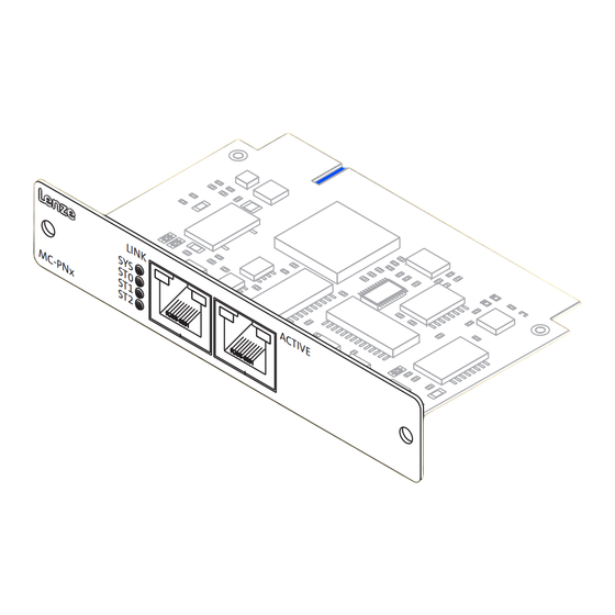
Page 19: Mc−Pnc, Mc−Pnd
PROFINET control, the controller interface connection (MC−PNC) serves to establish an individual control system on the basis of PROFINET. The MC card is used as directed if it is solely used in lenze device with MC card interface. A different use, or one beyond these purposes, is not permissible. - Page 20 Product description Variants MC−PNC, MC−PND Colour Status Meaning at MC−PNC Meaning at MC−PND Green Operating system is running Yellow Blinking with 1Hz Error during boot process Boot loader waits for boot process − No supply voltage or defect hardware Together with ST1 "Red On": no valid System error: master licence Watchdog time−out;...
- Page 21 Product description Variants MC−PNC, MC−PND Technical data MC−PNC, MC−PND Conformity, approval, directive Conformity EN 61000−6−4 EMC Directive Class A, EN 61000−6−2 industrial premises Approval UL 508 Process Control Equipment (File−No. E236341) CSA C22.2 Directive RoHS − Products lead−free in accordance with CE Directive 2011/65/EU General data and operating conditions See standard device...
- Page 22 Product description Variants MC−PNC, MC−PND MC−PND (device) I/O data Configurable up to max. 1024 bytes input Configurable up to max. 1024 bytes output Communication PROFINET IO−RT – VLAN and priority tagging – cyclic and acyclic Functions Cyclic process data Acyclic read and write requests Process and diagnostic alarm: 200 bytes Context management via CLRPC Generic diagnostics, channel diagnostics, extended...
-
Page 23: Electrical Installation
Electrical installation Important notes Electrical installation Important notes Stop! Short circuit and static discharges The printed circuit board and the standard device contain components which are endangered in the case of short circuit or static discharge. Possible consequences: The printed circuit board or devices connected are destroyed. ƒ... -
Page 24: Wiring And Configuration
Electrical installation Wiring and Configuration MC−CAN2 Wiring and Configuration 4.3.1 MC−CAN2 Wiring Pin assignment Description Connection type Cable type CAN bus connection Pin 1: not assigned Pin 2: CAN−LOW (LO) Pin 3: CAN−GND (CG) Pin 4: not assigned 9−pole SUB−D plug See following table Pin 5: not assigned Pin 6: CAN−GND (CG) - Page 25 XP, a device driver is required which is part of the "communication software (CAN)". It is included on the "PC based Automation" DVD and can also be found at www.Lenze.com in the download area. The device driver assumes the entire management of the interface.
- Page 26 (¶ 44). Note! Addressing the communication card from your own applications requires special programming skills. Lenze does not offer any support regarding this matter. The communication card is compatible with the technology of Peak (¶ 44). There you will get the required support.
- Page 27 Electrical installation Wiring and Configuration MC−CAN2 â Use of the MC card in Windows â In Windows CE the card interact via control system. All required drivers are installed Note! No special support is provided currently if you use the communication card in your own applications.
-
Page 28: Mc−Etc, Mc−Eth
Note! Addressing the communication card from your own applications requires special programming skills. Lenze does not offer any support regarding this matter. However, we can refer you to service providers who execute customised programming and are familiar with Lenze Industrial PCs. - Page 29 Electrical installation Wiring and Configuration MC−ETC, MC−ETH â Use of the MC card in Windows â You can use the card in Windows CE only with IPCs, not with controllers. â In order to be able to use the communication card in Windows CE, a device driver is required.
-
Page 30: Mc−Isi
Further settings: MC−ISI_003 Jumper Function plugged−on to ENA: default setting plugged−on to HW: default setting plugged−on: terminating resistor for RS422−/485 mode activated open: terminating resistor for RS422−/485 mode deactivated Do not assign JP2! Lenze service personnel only. BA_MC−Card EN 1.0... - Page 31 Electrical installation Wiring and Configuration MC−ISI Wiring COM A (RS232): Pin assignment Description Connection type Cable type Pin 1: DCD Pin 2: RXD Pin 3: TXD Pin 4: DTR Pin 5: GND 9−pole Sub−D plug Control cable Pin 6: DSR Pin 7: RTS Pin 8: CTS Pin 9: RI...
- Page 32 Note! Addressing the communication card from your own applications requires special programming skills. Lenze does not offer any support regarding this matter. However, we can refer you to service providers who execute customised programming and are familiar with Lenze Industrial PCs.
-
Page 33: Mc−Pbm, Mc−Pbs
Electrical installation Wiring and Configuration MC−PBM, MC−PBS 4.3.4 MC−PBM, MC−PBS Wiring Pin assignment Description Connection type Cable type PROFIBUS connection Pin 1: not assigned Pin 2: not assigned Pin 3: RxD/TxD−P(B) Pin 4: RTS 9−pole Sub−D socket See following table Pin 5: M5V Pin 6: P5V Pin 7: not assigned... - Page 34 The "cifX Device Driver" and the corresponding documentation can be found on the "PC based Automation" DVD or on the Internet at www.Lenze.com in the download area. BA_MC−Card EN 1.0...
- Page 35 Electrical installation Wiring and Configuration MC−PBM, MC−PBS X How to install the device driver: 1. Switch on the IPC after installing the communication card. The operating system recognises the new hardware and the "Found New Hardware Wizard" starts. 2. Select Install from a list or specific location. 3.
- Page 36 Electrical installation Wiring and Configuration MC−PBM, MC−PBS X How to configure the device driver: 1. Start the "cifX Driver Setup Utility": â – Open the Windows system control. – If you have set the "classic view", double−click the cifx Setup entry. If you have set the "category view", first select Other Control Panel Options in the left window area and then double−click the cifx Setup entry.
- Page 37 Electrical installation Wiring and Configuration MC−PBM, MC−PBS 3. Exit the "cifX Driver Setup Utility" application via the File W Quit menu. Note! Only for MC−PBM (Master): Configure the bus via the host application or the bus configurator ƒ "SyCon.net". Only for MC−PBS (Slave): Configure the bus via the warm start parameters in the "cifX Driver Setup ƒ...
-
Page 38: Mc−Pnc, Mc−Pnd
Electrical installation Wiring and Configuration MC−PNC, MC−PND 4.3.5 MC−PNC, MC−PND Wiring Description Connection type Cable type Ethernet connection Pin 1: TX+ Pin 2: TX− Pin 3: RX+ Network cable CAT5 S/UTP or Pin 4: Term1* RJ45 socket CAT5e S/FTP (recommended), cable length max. - Page 39 The "cifX Device Driver" and the corresponding documentation can be found on the "PC based Automation" DVD or on the Internet at www.Lenze.com in the download area. BA_MC−Card EN 1.0...
- Page 40 Electrical installation Wiring and Configuration MC−PNC, MC−PND X How to install the device driver: 1. Switch on the IPC after installing the communication card. The operating system recognises the new hardware and the "Found New Hardware Wizard" starts. 2. Select Install from a list or specific location. 3.
- Page 41 Electrical installation Wiring and Configuration MC−PNC, MC−PND X How to configure the device driver: 1. Start the "cifX Driver Setup Utility": â – Open the Windows system control. – If you have set the "classic view", double−click the cifx Setup entry. If you have set the "category view", first select Other Control Panel Options in the left window area and then double−click the cifx Setup entry.
- Page 42 No special support is provided currently if you use the communication card in your own applications. For special projects, please contact your sales office. B) Controller At the time the Lenze controllers can only communicate with the MC−PND via control system, not with the MC−PNC. â...
-
Page 43: Appendix
Appendix Use of the PCAN view/PCAN Explorer with MC−CAN2 Appendix Use of the PCAN view/PCAN Explorer with MC−CAN2 Peak System Technik GmbH provides the PCAN Explorer software for the diagnostics of a CAN network. The PCAN view program is the basic free−of−charge version of this program. When using these programs with the MC−CAN2 card, please observe the following: In the PCAN software, the MC−CAN2 card is not represented as hardware but as ƒ... -
Page 44: Contact Data Of System Partners
Appendix Contact data of system partners Contact data of system partners Hilscher Hilscher Gesellschaft für Systemautomation mbH Rheinstraße 15 D−65795 Hattersheim +49 6190 / 9907−0 www.hilscher.com Peak Peak System Technik GmbH Otto−Röhm−Str. 69 D−64293 Darmstadt +49 6151 / 8173−0 www.peak−system.com BA_MC−Card EN 1.0... - Page 45 Appendix Contact data of system partners BA_MC−Card EN 1.0...
- Page 46 © 11/2013 Lenze Automation GmbH Service Lenze Service GmbH Hans−Lenze−Str. 1 Breslauer Straße 3 D−31855 Aerzen D−32699 Extertal Germany Germany +49 (0)51 54 / 82−0 00 80 00 / 24 4 68 77 (24 h helpline) Ê Ê +49 (0)51 54 / 82 − 28 00 +49 (0)51 54 / 82−11 12...
Need help?
Do you have a question about the MC-CAN2 and is the answer not in the manual?
Questions and answers