Table of Contents
Advertisement
Available languages
Available languages
Quick Links
Advertisement
Chapters
Table of Contents
Troubleshooting

Related Manuals for Eliwell EWCFW-08


Summary of Contents for Eliwell EWCFW-08
- Page 1 Frequency Inverter Convertidor de Frecuencia Convertitore di Frequenza Frequenzumrichter Variateur de Vitesse EWCFW-08 User's Manual Manual del Usuario Manuale dell´utente Bedienungsanleitung Manuel d'utilisation...
- Page 3 FREQUENCY INVERTER MANUAL FREQUENCY INVERTER MANUAL MANUAL DEL CONVERTIDOR MANUAL DEL CONVERTIDOR DE FRECUENCIA DE FRECUENCIA MANUALE DEL CONVERTITORE DI MANUALE DEL CONVERTITORE DI FREQUENZA FREQUENZA BENIENUNGSANLEITUNG BENIENUNGSANLEITUNG FREQUENZUMRICHTER CFW-08 FREQUENZUMRICHTER CFW-08 VARIATEUR DE VITESSE MANUEL VARIATEUR DE VITESSE MANUEL Series: CFW-08 10000900189 / 02 E-S-I-G-F...
-
Page 4: Table Of Contents
CONTENTS / ÍNDICE / SOMMARIO / INHALTSVERZEICHNIS / RÉSUMÉ ENGLISH ....................... Quick Parameter Reference, Fault and Status Messages CHAPTER 1 - Safety Notices CHAPTER 2 - General Information CHAPTER 3 - Installation and Connection CHAPTER 4 - Keypad (HMI) Operation CHAPTER 5 - Start-up CHAPTER 6 - Diagnostics and Troubleshooting CHAPTER 7 - Technical Specifications... - Page 5 FREQUENCY INVERTER MANUAL Quick Parameter Reference, Fault and Status Messages CHAPTER 1 Safety Notices 1.1 Safety Notices in the Manual ..........16 1.2 Safety Notices on The Product ..........16 1.3 Preliminary Recommendations ..........16 CHAPTER 2 General Information 2.1 About this Manual ..............18 2.2 Software Version ..............
-
Page 7: Quick Parameter Reference, Fault And Status Messages
CFW-08 - QUICK PARAMETER REFERENCE QUICK PARAMETER REFERENCE, FAULT AND STATUS MESSAGES Software: V5.2X Application: Model: Serial Number: Responsible: Date: I. Parameters Factory User Parameter Function Adjustable Range Unit Page Setting Setting P000 Parameter Access 0 to 4 = Read 5 = Alteration 6 to 999 = Read READ ONLY PARAMETERS - P002 to P099... - Page 8 CFW-08 - QUICK PARAMETER REFERENCE Factory User Parameter Function Adjustable Range Unit Page Setting Setting Speed Limits P133 Minimum Frequency (F 0.00 to P134 3.00 P134 Maximum Frequency (F P133 to 300.0 66.00 V/F Control (2) (*) P136 Manual Torque Boost 0.0 to 30.0 5.0 or (IxR Compensation)
- Page 9 CFW-08 - QUICK PARAMETER REFERENCE Factory User Parameter Function Adjustable Range Unit Page Setting Setting Local/Remote Definition P220 Local/Remote 0 = Always Local Selection Source 1 = Always Remote 2 = HMI-CFW08-P or HMI-CFW08-RP Keypad (default: local) 3 = HMI-CFW08-P or HMI-CFW08-RP Keypad (default: remote) 4 = DI2 to DI4...
- Page 10 CFW-08 - QUICK PARAMETER REFERENCE Factory User Parameter Function Adjustable Range Unit Page Setting Setting P236 Analog Input AI1 Offset -999 to +999 P238 Analog Input AI2 Gain 0.00 to 9.99 1.00 (3)(5)(6) P239 Analog Input AI2 Function 0 = (0 to 10) V/(0 to 20) mA/ (**) (-10 to +10) V 1 = (4 to 20) mA...
- Page 11 CFW-08 - QUICK PARAMETER REFERENCE Factory User Parameter Function Adjustable Range Unit Page Setting Setting 11, 12 = Not Used 13 = Flying Start Disable 14 = Multispeed (MS1) Using Ramp 2 15 = Manual/Automatic (PID) 16 = Increase E.P. with Ramp 2 P266 Digital Input DI4 Function...
- Page 12 CFW-08 - QUICK PARAMETER REFERENCE Factory User Parameter Function Adjustable Range Unit Page Setting Setting Digital Output(s) P277 Relay Output RL1 Function 0 = Fs > Fx 1 = Fe > Fx 2 = Fs = Fe 3 = Is>Ix 4 and 6 = Not Used 5 = Run 7 = No Fault...
- Page 13 CFW-08 - QUICK PARAMETER REFERENCE Factory User Parameter Function Adjustable Range Unit Page Setting Setting P311 Voltage Ramp 0.1 to 10.0 Serial Communication Interface II P312 Serial Interface Protocol 0 = Serial Wbus 1 = Modbus-RTU 9600 bps without parity 2 = Modbus-RTU 9600 bps with odd parity 3 = Modbus-RTU 9600 bps...
- Page 14 CFW-08 - QUICK PARAMETER REFERENCE Factory User Parameter Function Adjustable Range Unit Page Setting Setting P407 Rated Motor Power 0.50 to 0.99 According to Factor the inverter model Measured Parameters (1) (3) P408 Run Self-Tuning 0 = No 1 = Yes ...
- Page 15 CFW-08 - QUICK PARAMETER REFERENCE II. Fault Messages Display Description Page Output overcurrent/short-circuit/output ground fault DC link overvoltage DC link undervoltage Overtemperature at the power heatsink or in the inverter internal air Output overload (Ixt function) External fault CPU error (Watchdog) Program memory error (Checksum) Keypad copy function error Self-tuning routine (estimation of the motor...
-
Page 16: Chapter 1 - Safety Notices
CHAPTER 1 SAFETY NOTICES This Manual contains necessary information for the correct use of the CFW-08 frequency inverter. This Manual was developed for qualified personnel with suitable training and technical qualification to operate this type of equipment. 1.1 SAFETY NOTICES IN The following safety notices are used in this manual: THE MANUAL DANGER! - Page 17 If necessary to do so, touch the properly grounded metallic frame or use a suitable ground strap. Do not apply high voltage (high pot) test on the inverter! If this test is necessary, contact Eliwell. NOTE! Inverters can interfere with other electronic equipment. In order to reduce this interference, adopt the measures recommended in chapter 3 - Installation and Connection.
-
Page 18: Chapter 2 - General Information
As the CFW-08 can be applied in several ways, it is impossible to describe here all of the application possibilities. Eliwell does not accept any responsibility when the CFW-08 is not used according to this manual. -
Page 19: About The Cfw-08
CHAPTER 2 - GENERAL INFORMATION The CFW-08 frequency inverter provides two control options: 2.3 ABOUT THE CFW-08 vector control (VVC: voltage vector control) or V/F (scalar); both types of control can be set according to the application. In the vector control mode, the motor performance is optimized relating to torque and speed regulation. - Page 20 CHAPTER 2 - GENERAL INFORMATION Rsh1 Power Motor Supply RFI Filter Rsh2 POWER CONTROL HMI-CFW08-RP HMI-CFW08-RP HMI-CFW08-P POWER SUPPLIES AND CONTROL / POWER INTERFACES KDC-24VR-CFW08 Interface MIP-CFW08-RP HMI-CFW08-RS 24 V Power Supply KDC-24V-CFW08 Interface MIS-CFW08-RS 24 V Power Supply KRS-485 "ECC3"...
- Page 21 CHAPTER 2 - GENERAL INFORMATION Braking Resistor (External and Optional) Pré-Carga Rsh1 Rede de Suppressor Motor Filter Alimentação (optional) RFI Filter Rsh2 Voltage Feedback POWER CONTROL HMI-CFW08-RP HMI-CFW08-RP HMI-CFW08-P POWER SUPPLIES AND CONTROL / POWER INTERFACES Interface KDC-24VR-CFW08 MIP-CFW08-RP HMI-CFW08-RS 24 V Power Supply KDC-24V-CFW08...
- Page 22 CHAPTER 2 - GENERAL INFORMATION DC Link Inductor Braking Resistor (optional) (optional) Pré-Carga Power Suppressor Motor Filter Supply (optional) RFI Filter Rsh1 Voltage Feedback POWER HMI-CFW08-P CONTROL HMI-CFW08-RP HMI-CFW08-RP POWER SUPPLIES AND CONTROL / POWER INTERFACES Interface MIP-CFW08-RP KDC-24VR-CFW08 HMI-CFW08-RS 24 V Power Supply Interface...
-
Page 23: Identification
CHAPTER 2 - GENERAL INFORMATION 2.4 CFW-08 IDENTIFICATION Eliwell Part Number Software Version CFW-08 Model (Intelligent Code) Manufacturing Date Rated Input Data Rated Output Data (Voltage, Current, etc) (Voltage, Frequency) Serial Number Lateral Label of the CFW-08 CFW-08 Model (Intelligent Code) - Page 24 CHAPTER 2 - GENERAL INFORMATION HOW TO SPECIFY THE CFW-08 MODEL: EWCFW-08 0043 Eliwell Rated Output Communication End Code Series 08 Current for: Option Frequency Inverter 0043 = 4.3A 0 = No 0065 = 6.5A communication 0100 = 10A 0130 = 13A...
- Page 25 CHAPTER 2 - GENERAL INFORMATION For the effect of this code, the standard product is conceived as follows: - CFW-08 with standard control board. - Degree of protection: Nema 1 for the models 22 A, 28 A and 33 A/ 200-400 V and also 13 A,16 A, 24 A and 30 A/380-480 V, IP20 for the other models.
-
Page 26: Receiving And Storing
CHAPTER 2 - GENERAL INFORMATION 2.5 RECEIVING AND The CFW-08 is supplied in cardboard boxes. STORING The outside of the packing box has a nameplate that is identical to that on the CFW-08. Please check if the CFW-08 is the one you ordered. Check if the: CFW-08 nameplate data matches with your purchase order. -
Page 27: Chapter 3 - Installation And Connection
CHAPTER 3 INSTALLATION AND CONNECTION This chapter describes the procedures for the electrical and mechanical installation of the CFW-08. These guidelines and suggestions must be followed for proper CFW-08 operation. The location of the inverter installation is an important factor 3.1 MECHANICAL to assure good performance and long useful life for its INSTALLATION... - Page 28 CHAPTER 3 - INSTALLATION AND CONNECTION - ONLY REMOVE TERMINAL COVER WARNING AFTER 1 MIN. POWER HAS BEEN DISCONNECTED. - READ THE INSTRUCTIONS MANUAL. - SOMENTE REMOVA A TAMPA 1 MIN. APÓS A DESENERGIZAÇÃO. ATENÇÃO - LEIA O MANUAL DE INSTRUÇÕES. VIEW OF THE FRONTAL LATERAL VIEW...
- Page 29 CHAPTER 3 - INSTALLATION AND CONNECTION Dimensions Fixing base Weigth Width L Height H Depth P Inverter Mounting Degree of Model Screw Protection (lb) (in) (in) (in) (in) (in) (in) (in) 1.6 A / 200-240 V IP20 / Nema 1 (2.95) (5.95) (5.16)
- Page 30 CHAPTER 3 - INSTALLATION AND CONNECTION 3.1.3 Positioning and Fixing When installing the CFW-08, free space around the inverter must be left as indicated in figure 3.2. Table 3.2 shows the required free spaces. Install the inverter in vertical position according to the following recommendations: 1) Install the inverter on a flat surface.
- Page 31 CHAPTER 3 - INSTALLATION AND CONNECTION CFW-08 Model 1.6 A / 200-240 V 2.6 A / 200-240 V 4.0 A / 200-240 V 7.0 A / 200-240 V 30 mm 1.18 in 5 mm 0.20 in 50 mm 2 in 50 mm 2 in 1.0 A / 380-480 V...
-
Page 32: Electrical Installation
CHAPTER 3 - INSTALLATION AND CONNECTION 3.1.3.2 Surface Mounting Figure 3.3 shows the surface installation procedures of the CFW-08. AIR FLUX Figure 3.3 - Mounting procedures for CFW-08 3.2 ELECTRICAL INSTALLATION DANGER! The information below will be a guide to achieve a proper installation. - Page 33 CHAPTER 3 - INSTALLATION AND CONNECTION -UD: negative pole of the DC link circuit is not available on the models 1.6 A-2.6 A-4.0 A-7.0 A/200-240 V and models 1.0 A-1.6 A-2.6 A-4.0 A/380-480 V. It is used when the inverter supplied by DC voltage (with the terminal +UD). In order to avoid an incorrect braking resistor connection (mounted outside the inverter), there is a protective rubber plug on this terminal, which must be removed if the –UD...
- Page 34 CHAPTER 3 - INSTALLATION AND CONNECTION d) 28-33 A/200-240 V and 24-30 A/380-480 V models MOTOR LINE Figure 3.4 (cont.) d) - Power terminals 3.2.2 Location of the Power a) 1.6-2.6-4.0-7.0-7.3-10-16 A/200-240 V and 1.0-1.6-2.6-2.7-4.0-4.3-6.5-10 A/380-480 V models Terminals, Grounding Terminals and Control Terminal Connections Control XC1...
- Page 35 CHAPTER 3 - INSTALLATION AND CONNECTION 3.2.3 Power/Grounding Wiring and Circuit Breakers ATTENTION! Install the inverter and power cables distant from sensitive equipment and wirings by 0.25 m (0.82 ft), for instance PLCs, temperature controllers, thermocouple cables, etc. Use the recommended wire cross section and circuit breakers as shown in table 3.4.
- Page 36 CHAPTER 3 - INSTALLATION AND CONNECTION Grounding Wiring Power Cables Type of Screwdriver for Model Lbf.in Lbf.in the Power Terminal 1.6 A / 200-240 V 4.34 8.68 Philips Number PH2 2.6 A / 200-240 V 4.34 8.68 Philips Number PH2 4.0 A / 200-240 V 4.34 8.68...
- Page 37 CHAPTER 3 - INSTALLATION AND CONNECTION b) 7.3-10-16-22 A/200-240 V and 2.7-4.3-6.5-10-13-16 A/380-480 V models - Three phase power supply Braking -Ud BR Resistor Shielding Power Supply Circuit Breaker c) 1.6-2.6-4.0-7.3-10 A / 200-240 V models - Single phase power supply Braking -Ud BR Resistor...
- Page 38 CHAPTER 3 - INSTALLATION AND CONNECTION d) 28-33 A / 200-240 V and 24-30 A / 380-480 V models - Three phase power supply DC Link -Ud BR Inductor (Optional) Phase Shielding Braking Resistor Power Supply Circuit Breaker Figure 3.6 d) - Power and grounding connections 3.2.4.1 AC Input Connection DANGER! Provide an AC disconnecting switch to switch OFF the input...
- Page 39 CHAPTER 3 - INSTALLATION AND CONNECTION If the CFW-08 is installed in networks which can supply more than 30.000 Arms, you must provide suitable protection circuits such as fuses and circuit breakers. DC link inductor / line reactors The requirements for use of line reactors or DC link inductor depend on several application factors.
- Page 40 CHAPTER 3 - INSTALLATION AND CONNECTION GROUNDING BAR INTERNAL TO THE PANEL Figure 3.7 - Grounding connections for more than one inverter ATTENTION! The AC input for the inverter must have a grounded neutral conductor. EMI – Electromagnetic interference When electromagnetic interference (EMI) generated by the inverter interferes in the performance of other equipment, use shielded wires, or install the motor wires in metallic conduits.
- Page 41 CHAPTER 3 - INSTALLATION AND CONNECTION The signal connections (analog inputs/outputs) and control 3.2.5 Signal and Control connections (digital inputs and relay outputs) are made on Connections the XC1 connector of control board (refer to the location in figure 3.5, item 3.2.2). There are two configurations for the control board: standard version (CFW-08 line) and Plus version (CFW-08 Plus line), as shown below:...
- Page 42 CHAPTER 3 - INSTALLATION AND CONNECTION Connector Description Specifications Factory Default Function Digital Input 1 4 isolates digital inputs - Logic NPN No Function or General Enable Minimum high level: 10 Vdc Digital Input 2 Maximum high level: 30 Vdc FWD / REV Maximum low level: 3 Vdc Digital Input 3...
- Page 43 CHAPTER 3 - INSTALLATION AND CONNECTION Figure 3.10 - Jumpers position for selecting the analog inputs and outputs operation mode (voltage - 0 to 10 Vdc or current - 0 to 20 mA / 4 to 20 mA) as well as the digital inputs operation mode (high logic level - PNP or low logic level - NPN).
- Page 44 CHAPTER 3 - INSTALLATION AND CONNECTION During the signal and control wire installation note the following: 1) Cable cross section: (0.5 to 1.5) mm²/(20 to 14) AWG 2) Maximum Torque: 0.50 N.m (4.50 lbf.in). 3) XC1 wiring must be connected with shielded cables and installed at least 10 cm (3.9 in) minimum separately from other wiring (power, control at 110/220 V, etc) for lengths up to 100 m (330 ft) and 25 cm (9.8 in) minimum for total...
- Page 45 CHAPTER 3 - INSTALLATION AND CONNECTION 3.2.5.1 Digital Inputs as This option can be selected when a PLC is used with relay or Low Level Active transistor output is used (low logic level to activate the DI). (S1:1 to OFF) a) Example using a PLC - relay output Connector XC1 PLC output relay...
- Page 46 CHAPTER 3 - INSTALLATION AND CONNECTION 3.2.5.2 Digital Input as This option can be selected when a PLC is used with PNP High Level Active transistor output (high logic level to activate the DI) or PLC (S1:1 to ON) with relay output is used. For this last alternative you must apply an external power supply 24 V +/- 10 %.
- Page 47 CHAPTER 3 - INSTALLATION AND CONNECTION NOTES! The inverter is factory default programmed with the digital inputs as low level active (S1:1 in OFF). When the digital inputs are used as high level active, you must set the jumper S1:1 to ON. The jumper S1:1 selects the high level or low level active for all 4 digital inputs.
- Page 48 CHAPTER 3 - INSTALLATION AND CONNECTION NOTES! For the proper operation of configuration 2, terminal 5 shall be connected to terminal 1 (general enable). The frequency reference can be sent via AI1 analog input (as shown in figure 3.16), via keypad HMI-CFW08-P, or via any other source (as described in the parameters P221 and P222).
- Page 49 CHAPTER 3 - INSTALLATION AND CONNECTION NOTES! S1 and S2 are push buttons, start (NO contact) and stop (NC contact), respectively. The speed reference can be via analog input AI1 (as in Connection 2), via keypad (HMI-CFW08-P), or via any other source (as described in the parameters P221 and P222).
-
Page 50: European Emc Directive - Requirements For Conforming Installations
CHAPTER 3 - INSTALLATION AND CONNECTION 3.3 EUROPEAN EMC The CFW-08 inverter series was designed considering safety DIRECTIVE - and EMC (Electromagnetic Compatibility) aspects. REQUIREMENTS The CFW-08 units do not have an intrinsic function until FOR CONFORMING connected with other components (e. g. a motor). Therefore, INSTALLATIONS the basic product is not CE marked for compliance with the EMC Directive. - Page 51 CHAPTER 3 - INSTALLATION AND CONNECTION 4) The length of the wiring between filter and inverter must be kept as short as possible. 5) The cables shielding (motor and control) must be solidly connected to the common back plate, using a metal bracket. 6) Grounding as recommended in this manual.
- Page 52 CHAPTER 3 - INSTALLATION AND CONNECTION Notes: (1) First environment: includes domestic premises. It also includes establishments directly connected without intermediate transformers to a low-voltage power supply network which supplies buildings used for domestic purposes. (2) Second environment: includes all establishments other than those directly connected to a low-voltage power supply network which supplies buildings used for domestic purposes.
- Page 53 CHAPTER 3 - INSTALLATION AND CONNECTION 3.3.3 Inverter Models Table 3.8 below shows the inverter models and the respective and Filters RFI filter and the EMC category. The description of each EMC categories is given in item 3.3.2. The characteristics of the footprint and external input RFI filters are given in item 3.3.4.
- Page 54 CHAPTER 3 - INSTALLATION AND CONNECTION Conducted Emission Radiated Emission Inverter Model Input RFI Filter Level Level B84143-B36-R110 CFW080220T2024... (external filter) Category C1 Category C2 B84143-B50-R110 CFW080280T2024... (external filter) B84143-B50-R110 CFW080330T2024... Category C1 Category C2 (external filter) CFW080010T3848...FAZ CFW080016T3848...FAZ FEX2-CFW08 CFW080026T3848...FAZ (footprint filter) CFW080040T3848...FAZ...
- Page 55 CHAPTER 3 - INSTALLATION AND CONNECTION cabinet is required, the maximum length of the remote keypad cable is 3 m (9.84 ft). In this case, the remote keypad, the control and signal wiring must be located inside the cabinet (the remote keypad can be installed in the cabinet front door, refer to items 8.6.1 and 8.8).
- Page 56 Characteristics Dimensions Rated Weight Filter Drawings Manufacturer (Width x Height Current (kg/lb) x Depth in mm [in]) FEX1-CFW08 10 A 79x190x51 Eliwell 0.6/1.32 Figure 3.20 FEX2-CFW08 [3.11x7.48x2] 85.5x119x57.6 FS6007-16-06 16 A 0.9/1.98 Figure 3.21 [3.37x4.68x2.27] FS6007-25-08 25 A 1.0/2.2 85.5x119x57.6 Figure 3.22...
- Page 57 CHAPTER 3 - INSTALLATION AND CONNECTION a) Footprint Filter b) Footprint Filter and Inverter Lateral Right Front View View Bottom View Front View Lateral Right View Terminal block for Bottom View flexible or rigid cable of 4 mm or AWG 10. Max.
- Page 58 CHAPTER 3 - INSTALLATION AND CONNECTION 57.6 98.5 15.6 Bolt type 08 = M4 Note: figure dimensions are in mm. Figure 3.22 - FS6007-25-08 and FS6007-36-08 external filter drawing Mechanical Data 41,8 Rated Current 30,3 11,5 Type/45 Terminal block for 6 mm solid cable, 4 mm flexible cable AWG 12.
- Page 59 CHAPTER 3 - INSTALLATION AND CONNECTION Toroid: Thornton NT35/22/22-4100-IP12R Plastic clamp: HellermannTyton NXR-18 19.3 33.3 to 38.1 Note: figure dimensions are in mm. Figure 3.24 - TOR1-CFW08 drawing Toroid: Thornton NT52/32/20-4400-IP12E Note: figure dimensions are in mm. Figure 3.25 - TOR2-CFW08 drawing...
- Page 60 CHAPTER 3 - INSTALLATION AND CONNECTION NOTE! The following filters drawings belong to Epcos. It is possible to get further information about them in the Epcos website. 199,5 Not used for Terminals 4 mm connection Tightening torque of screw 0,5 - 0,6 Nm PE M5 Tightening torque 2,8 ±...
- Page 61 CHAPTER 3 - INSTALLATION AND CONNECTION Litz wire 2,5 mm Terminals 4 mm Tightening torque of screw 0,7 ± 0,1 Nm 300 ±10 Marking Earth connector M6 x 25 Tightening torque 4,8 ± 0,2 Nm 215 ±0,5 Marking Note: figure dimensions are in mm. Figure 3.28 - External filter drawing B84143-B16-R110 PE M5x19 Tightening torque 2 ±...
- Page 62 CHAPTER 3 - INSTALLATION AND CONNECTION Terminals 6 mm Tightening torque 1,5 - 1,8 Nm 400 ±10 Litz wire 4 mm 265 ±0,5 Marking PE M6x24 Tightening torque 3 ± 0,15 Nm Marking Load Line Note: figure dimensions are in mm. Figure 3.30 - External filter drawing B84143-B36-R110 Terminals 10 mm Tightening torque of screw 1,2 - 1,5 Nm...
- Page 63 CHAPTER 3 - INSTALLATION AND CONNECTION Litz wire 10 mm Terminals 16 mm Tightening torque of screw 1,65 ± 0,15 Nm 500 ±10 315 ±0,5 Earth connector M6x25 Tightening torque 4,8 ± 0,2 Nm Marking Note: figure dimensions are in mm. Figure 3.32 - External filter drawing B84143-B50-R110 Terminals 10 mm Tightening torque of screw 1,2 - 1,5 Nm...
- Page 64 CHAPTER 3 - INSTALLATION AND CONNECTION Litz wire 1,5 mm Terminals 4 mm Tightening torque of screw 0,7 ± 0,1 Nm 300 ±10 Marking Earth connector M6x25 Tightening torque 4,8 ± 0,2 Nm 215 ±0,5 Marking Note: figure dimensions are in mm. Figure 3.34 - External filter drawing B84143-B8-R110 Terminals 6 mm Tightening torque 1,5 - 1,8 Nm...
- Page 65 CHAPTER 3 - INSTALLATION AND CONNECTION Terminals 6 mm Tightening torque 1,5 - 1,8 Nm 400 ±10 Litz wire 6 mm 265 ±0,5 Marking PE M6x24 Tightening torque 3 ± 0,15 Nm Marking Line Load Note: figure dimensions are in mm. Figure 3.36 - External filter drawing B84143-G36-R110...
-
Page 66: Chapter 4 - Keypad (Hmi) Operation
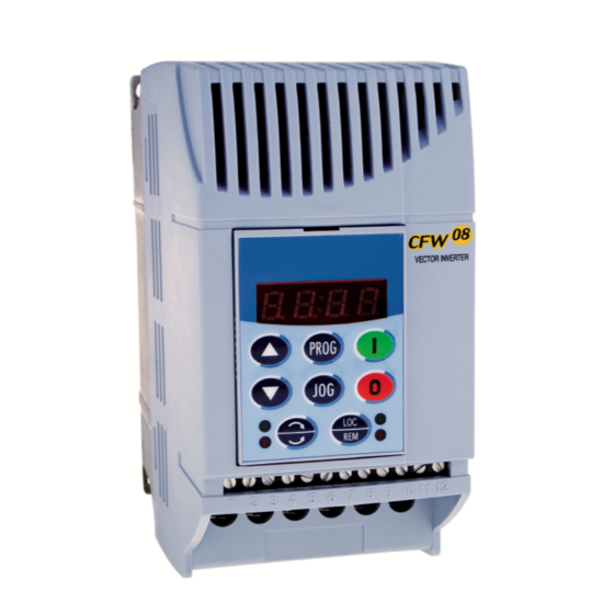
CHAPTER 4 KEYPAD (HMI) OPERATION This chapter describes the standard Human Machine Interface (HMI) of the inverter (HMI-CFW08-P) and the manner to use it, presenting the following information: General keypad description. Use of the keypad. Parameter programming and reading. Description of the status indications and signalizations. The standard CFW-08 keypad has a LED display with 4 digits 4.1 KEYPAD (HMI) of 7 segments, 4 status LEDs and 8 keys. -
Page 67: Use Of The Keypad Hmi
CHAPTER 4 - KEYPAD (HMI) OPERATION FWD/REV Control Selection FWD / REV Forward Forward Reverse HMI LED Situation Flashing Figure 4.2 - Direction of rotation (FWD/REV) LEDs Basic functions of the keys: Starts the inverter via acceleration ramp. Stops (disables) the inverter via deceleration ramp. Also resets inverter after a fault has occurred. - Page 68 CHAPTER 4 - KEYPAD (HMI) OPERATION Operation of the inverter (keys ) and speed reference setting (keys 4.2.1 Keypad Operation All functions relating to the CFW-08 operation (Start/Stop, Direction of Rotation, JOG, Increment/Decrement, Speed (Frequency) Reference, and selection of Local/Remote mode) can be performed through the HMI selection.
- Page 69 CHAPTER 4 - KEYPAD (HMI) OPERATION Parameter P121 stores the speed (frequency) reference set by the keys: When pressed, it increases the speed (frequency) reference. When pressed, it decreases the speed (frequency) reference. Reference Backup: The last frequency reference set by the keys stored when inverter is stopped or the AC power is removed, provided P120 = 1 (reference backup active is the factory default).
- Page 70 CHAPTER 4 - KEYPAD (HMI) OPERATION 4.2.3 Read-Only Parameters Parameters P002 to P099 are reserved for the display of read- only values. The factory default display when power is applied to the inverter is P002 (frequency proportional value in V/F control mode (P202 = 0 or 1) and motor speed in rpm in vector control mode (P202 = 2)).
- Page 71 CHAPTER 4 - KEYPAD (HMI) OPERATION NOTE! (1) For parameters that can be changed with the motor running, the inverter will use the new value immediately after it has been set. For parameters that can be changed only with motor stopped, the inverter will use this new value only after the key is pressed.
- Page 72 CHAPTER 4 - KEYPAD (HMI) OPERATION Programming Error – E24 P265 = 3 and other(s) D I(s) Start-Stop or FWD and REV or ON and OFF P266 = 3 and other(s) D I(s) Start-Stop or FWD and REV or ON and OFF P267 = 3 and other(s) D I(s) ...
-
Page 73: Chapter 5 - Start-Up
CHAPTER 5 START-UP This chapter provides the following information: How to check and prepare the inverter before power-up. How to power-up and check for proper operation. How to operate the inverter when it is installed according to the typical connections (refer to item 3.2 - Electrical Installation). -
Page 74: Start-Up
CHAPTER 5 - START-UP The four LEDs of the keypad remains ON during this procedure. Inverter runs some self-diagnosis routines. If no problems are found, the display shows: This means that the inverter is ready (rdy = ready) to be operated. - Page 75 CHAPTER 5 - START-UP 5.3.1 Start-up - The sequence below is valid for the connection 1 (refer to item Operation via Keypad 3.2.6). Inverter must be already installed and powered up (HMI) - Type of Control: according to chapter 3 and item 5.2. Linear V/F (P202 = 0) Connections according to figure 3.6.
-
Page 76: Faults And Possible Causes
CHAPTER 6 DIAGNOSTICSAND TROUBLESHOOTING This chapter assists the user to identify and correct possible faults that can occur during the CFW-08 operation. Instructions about required periodical inspections and cleaning procedures are also provided. 6.1 FAULTS AND When a fault is detected, excepting the faults related to the POSSIBLE CAUSES serial communication,the inverter is disabled and the fault code is displayed on the readout in EXX form, where XX is... -
Page 77: Chapter 6 - Diagnostics And Troubleshooting
Any DI programmed for external fault External fault detection is open (not connected to GND - XC1) Electrical noise CPU error (Watchdog) Contact Eliwell Memory with corrupted values Program memory error (Checksum) Power-on Defective contact in the HMI-CFW08-RS cable Keypad copy... - Page 78 Bad contact or short-circuit (resistance < 100 ) on wiring at terminals XC1:6 and 7 or XC1:7 and 8 of the control board (wiring that comes from the motor thermistor - PTC) Contact Eliwell Inverter power circuit is defective Self- diagnosis fault Table 6.1 (cont.) - Errors, possible causes and reset ways...
-
Page 79: Troubleshooting
CHAPTER 6 - DIAGNOSTICS AND TROUBLESHOOTING references” at P120 has been enabled), the occurred fault number, the status of the integrator of the IxT function (overcurrent). E24: indicates the fault code on the LED display. E31: inverter proceeds to operate normally, but it does not accept the keypad commands;... - Page 80 CHAPTER 6 - DIAGNOSTICS AND TROUBLESHOOTING POINT TO BE PROBLEM CORRECTIVE ACTION CHECKED Motor speed too Programming error 1.Check if the contents of P133 (minimum frequency) and P134 (maximum frequency) are according to the motor and to the high or too low (reference limits) application.
-
Page 81: Power Data
CHAPTER 7 TECHNICAL SPECIFICATIONS This chapter describes the technical specifications (electrical and mechanical) of the CFW-08 inverter series. AC Input Specifications: 7.1 POWER DATA Voltage: + 10 %, -15 % (with loss of motor efficiency) Frequency : 50/60 Hz (± 2 Hz) Phase unbalance: ... -
Page 82: Chapter 7 - Technical Specifications
CHAPTER 7 - TECHNICAL SPECIFICATIONS 7.3/ Model: Current (A) / Voltage (V) 200-240 200-240 200-240 200-240 200-240 200-240 Power (kVA) 10.7 12.6 Rated output current (A) Max. output current (A) 49.5 Single-phase or Power supply Three- phase three-phase Rated input current (A) 8.6/16 12/22 33.6... - Page 83 CHAPTER 7 - TECHNICAL SPECIFICATIONS Model: Current (A) / Voltage (V) 380-480 380-480 380-480 380-480 18.3 Power (kVA) 12.2 Rated output current (A) Maximum output current (A) 19.5 Three- phase Power supply 28.8 Rated input current (A) Switching frequency (kHz) 15 HP/ 20 HP/ 7.5 HP /...
- Page 84 CHAPTER 7 - TECHNICAL SPECIFICATIONS (4) Rated input current for single-phase operation. Note: the models CFW080016B2024..., CFW080026B2024..., CFW080040B2024..., CFW080073B2024 ... and CFW080100B2024 ... can be operated both with single-phase voltage and three-phase voltage without output current derating. (5) The indicated motor power ratings are only orientative values for IV-pole motors and normal duty loads.
-
Page 85: Electronics/General Data
CHAPTER 7 - TECHNICAL SPECIFICATIONS 7.2 ELECTRONICS/GENERAL DATA Voltage Source Inverter METHOD V/F Control or Sensorless Vector Control (V.V.C. - Voltage Vector Control) CONTROL PWM SVM (Space Vector Modulation) OUTPUT 0 to 300 Hz, resolution of 0.01 Hz FREQUENCY V/F CONTROL Speed regulation: 1 % of the rated speed PERFORMANCE VECTOR... - Page 87 MANUAL DEL CONVERTIDOR DE FRECUENCIA CAPÍTULO 1 Instrucciones de Seguridad 1.1 Avisos de Seguridad en el Manual ........89 1.2 Avisos de Seguridad en el Producto ........89 1.3 Recomendaciones Preliminares ........... 89 CAPÍTULO 2 Informaciones Generales 2.1 Sobre el Manual ..............91 2.2 Versión de Software ..............
-
Page 89: Avisos De Seguridad En El Manual
CAPÍTULO 1 INSTRUCCIONES DE SEGURIDAD Este manual contiene las informaciones necesarias para el uso correcto del convertidor de frecuencia CFW-08. Fue escrito para ser utilizado por personas con entrenamiento o calificación técnica adecuados para operar este tipo de equipamiento. 1.1 AVISOS DE En el texto serán utilizados los siguientes avisos de seguridad: SEGURIDAD EN EL MANUAL... -
Page 90: Capítulo 1 - Instrucciones De Seguridad
CAPÍTULO 1 - INSTRUCCIONES DE SEGURIDAD ¡ NOTA! Para los propósitos de este manual, personas calificadas son aquellas entrenadas de forma a estar aptas para: 1. Instalar, hacer la puesta a tierra, energizar y operar el CFW-08 de acuerdo con este manual y los procedimientos legales de seguridad vigentes;... -
Page 91: Sobre El Manual
CFW-08 no basado en este manual. Es prohibido la reproducción del contenido de este manual, en todo o en partes, sin la permisión por escrito de Eliwell. La versión del software usado en el CFW-08 es importante porque 2.2 VERSIÓN DE... -
Page 92: Capítulo 2 - Informaciones Generales
CAPÍTULO 2 - INFORMACIONES GENERALES 2.3 SOBRE EL El convertidor de frecuencia CFW-08 posee en el mismo producto CFW-08 un control V/F (escalar) y un control vectorial sensorless (VVC: voltage vector control) programables. El usuario puede optar por uno o otro método de control de acuerdo con la aplicación. En el modo vectorial la operación es optimizada para el motor en uso obteniéndose un mejor desempeño en termos de par y regulación de velocidad. - Page 93 CAPÍTULO 2 - INFORMACIONES GENERALES Rsh1 Red de Motor Alimentación Filtro RFI Rsh2 POTENCIA CONTROL HMI-CFW08-RP HMI-CFW08-RP HMI-CFW08-P FUENTES PARA ELECTRÓNICA Y INTERFACES ENTRE POTENCIA Y CONTROL KDC-24VR-CFW08 Interface MIP-CFW08-RP HMI-CFW08-RS Fuente 24 V KDC-24V-CFW08 Interface MIS-CFW08-RS Fuente 24 V KRS-485 "ECC3"...
- Page 94 CAPÍTULO 2 - INFORMACIONES GENERALES Resistor de Frenado (Opcional) Pré-Carga Rsh1 Filtro Red de Supresor Motor Alimentación (Opcional) Filtro RFI Rsh2 Realimentación de Tensión POTENCIA CONTROL HMI-CFW08-RP HMI-CFW08-RP HMI-CFW08-P FUENTES PARA ELECTRÓNICA Y INTERFACES ENTRE POTENCIA Y CONTROL Interface KDC-24VR-CFW08 MIP-CFW08-RP HMI-CFW08-RS Fuente 24 V...
- Page 95 CAPÍTULO 2 - INFORMACIONES GENERALES Indutor de Link CC Resistor de (Opcional) Frenado (Opcional) Precarga Filtro Red de Supresor Motor Alimentación (Opcional) Filtro RFI Rsh1 Realimentación de Tensión POTENCIA HMI-CFW08-P CONTROL HMI-CFW08-RP HMI-CFW08-RP FUENTES PARA ELECTRÓNICA Y INTERFACES ENTRE POTENCIA Y CONTROL Interface MIP-CFW08-RP...
-
Page 96: Etiquetas De Identificación Del Cfw-08
(Tensión, Corriente, etc.) (Tensión, Frecuencia) Número Serial Etiqueta Lateral del CFW-08 Modelo (Código inteligente del convertidor) EWCFW080130S0 Ítem de stock Eliwell Versión del Software 12345678 V 1.234 1234567890 20/02/2008 Fecha de Fabricación Número Serial Etiqueta Frontal del CFW-08 (sob la HMI) Etiqueta de certificaciones Figura 2.4 - Descripción y ubicación de las etiquetas de identificación en el CFW-08... - Page 97 CAPÍTULO 2 - INFORMACIONES GENERALES COMO ESPECIFICAR EL MODELO DEL CFW-08: EWCFW-08 0043 Convertidor de Corriente de Opzione di Fine del Frecuencia Salida Nominal comunicazione codice Eliwell para: Serie 08 0 = Nessuna 0043 = 4.3A comunicazione 0065 = 6.5A...
- Page 98 CAPÍTULO 2 - INFORMACIONES GENERALES El producto estándar, para efectos de este código, es así concebi- - CFW-08 con tarjeta de control padrón. - Grado de protección: NEMA 1 en los modelos 22 A, 28 A y 33 A / 200-240 V y 13 A,16 A, 24 A y 30 A / 380-480 V;...
-
Page 99: Recibimientoy Almacenaje
CAPÍTULO 2 - INFORMACIONES GENERALES 2.5 RECIBIMIENTO El CFW-08 es suministrado empaquetado en caja de cartón. Y ALMACENAJE En la parte externa de este embalaje existe una etiqueta de identificación que es la misma que está afijada en la lateral del convertidor. -
Page 100: Instalación Mecánica
CAPÍTULO 3 INSTALACIÓN Y CONEXIÓN Este capítulo describe los procedimientos de instalación eléctrica y mecánica del CFW-08. Las orientaciones y sugestiones deben ser seguidas visando el correcto funcionamiento del convertidor. 3.1 INSTALACIÓN MECÁNICA 3.1.1 Ambiente La localización de los convertidores es un factor determinante para la obtención de un funcionamiento correcto y una vida normal de sus componentes. -
Page 101: Capítulo 3 - Instalación Y Conexión
CAPÍTULO 3 - INSTALACIÓN Y CONEXIÓN - ONLY REMOVE TERMINAL COVER WARNING AFTER 1 MIN. POWER HAS BEEN DISCONNECTED. - READ THE INSTRUCTIONS MANUAL. - SOMENTE REMOVA A TAMPA 1 MIN. APÓS A DESENERGIZAÇÃO. ATENÇÃO - LEIA O MANUAL DE INSTRUÇÕES. VISTA DE LA BASE VISTA VISTA LATERAL... -
Page 102: Ip20/Nema
CAPÍTULO 3 - INSTALACIÓN Y CONEXIÓN Dimensiones Base de Fijación Tornillo Peso Grado de Ancho L Profun- Modelo Alto H para Proteción didad P Fijación (lb) (in) (in) (in) (in) (in) (in) (in) 1.6 A / 200-240 V IP20 / (0.24) (2.95) (5.16) - Page 103 CAPÍTULO 3 - INSTALACIÓN Y CONEXIÓN 3.1.3 Posicionamiento Para la instalación del CFW-08 se debe dejar en el mínimo os y Fijación espacios libres al rededor del convertidor conforme la figura 3.2 a seguir. Las dimensiones de cada espacio están descriptas en la tabla 3.2.
- Page 104 CAPÍTULO 3 - INSTALACIÓN Y CONEXIÓN CFW-08 Modelo 1.6 A / 200-240 V 2.6 A / 200-240 V 4.0 A / 200-240 V 7.0 A / 200-240 V 30 mm 1.18 in 5 mm 0.20 in 50 mm 2 in 50 mm 2 in 1.0 A / 380-480 V...
-
Page 105: Instalación Eléctrica
CAPÍTULO 3 - INSTALACIÓN Y CONEXIÓN 3.1.3.2 Montaje La figura 3.3 presenta el procedimiento de instalación del CFW-08 en Superficie en la superficie de montaje. Flujo de Aire Figura 3.3 - Procedimiento de instalación del CFW-08 3.2 INSTALACIÓN ELÉCTRICA ¡ PELIGRO! Las infomaciones que siguen tienen la intensión de servir como guía para obtenerse una instalación correcta. - Page 106 CAPÍTULO 3 - INSTALACIÓN Y CONEXIÓN -UD: Polo negativo de la tensión del circuito intermediario (Link CC). No disponible en los modelos 1,6 A-2,6 A-4,0 A-7,0 A/200-240 V y en los modelos 1,0 A-1,6 A-2,6 A-4,0 A/380-480 V. Es utilizado cuando se desea alimentar el convertidor con tensión CC (justa- mente con el borne +UD).
- Page 107 CAPÍTULO 3 - INSTALACIÓN Y CONEXIÓN d) Modelos 28-33 A/200-240 V y 24-30 A/380-480 V LINE MOTOR Figura 3.4 d) - Bornes de la potencia a) Modelos 1,6-2,6-4,0-7,0-7,3-10-16 A/200-240 V y 3.2.2 Ubicación de 1,0-1,6-2,6-2,7-4,0-4,3-6,5-10 A/380-480 V las conexiones de potencia, puesta a tierra y control Control XC1...
- Page 108 CAPÍTULO 3 - INSTALACIÓN Y CONEXIÓN 3.2.3 Cableado de Potencia / Puesta a Tierra y Disyuntores ¡ ATENCIÓN! Alejar los equipameintos y cables sensibles en 0,25 m del convertidor y de los cables de conexión entre convertidor y motor. Ejemplo: CLPs, controladores de temperatura, cables de los termopares, etc.
- Page 109 CAPÍTULO 3 - INSTALACIÓN Y CONEXIÓN Cables de Puestaa Tierra CableadodePotencia Tipo de Llave p/ Borne Modelo Lbf.in Lbf.in de Potencia 1,6 A / 200-240 V 4,34 8,68 Philips Nº PH2/fenda 2,6 A / 200-240 V 4,34 8,68 Philips Nº PH2/fenda 4,0 A / 200-240 V 4,34 8,68...
- Page 110 CAPÍTULO 3 - INSTALACIÓN Y CONEXIÓN b) Modelos 7,3-10-16-22 A/200-240 V y 2,7-4,3-6,5-10-13-16 A/380-480 V - Alimentación trifásica Resistor de -Ud B R +Ud Frenado Blindaje Disyuntor c) Modelos 1,6-2,6-4,0-7,3-10 A / 200-240 V - Alimentación monofásica Resistor (**) de B R +Ud Frenado Fase...
- Page 111 CAPÍTULO 3 - INSTALACIÓN Y CONEXIÓN d) Modelos 28-33 A / 200-240 V y 24-30 A / 380-480 V - Alimentación trifásica Indutor del Link CC (Opcional) -Ud BR Fase Blindage Resistor de Frenado Disyuntor Figura 3.6 d) - Conexiones de potencia y aterramiento 3.2.4.1 Conexiones de la Entrada CA ¡...
- Page 112 CAPÍTULO 3 - INSTALACIÓN Y CONEXIÓN Indutor del Link CC / Reactancia de la Red La necesidad del uso de reactancia de red o inductor del Link CC depiende de vários factores. ¡ NOTA! Condensadores de corrección de factor de potencia no son necesarios en la entrada (L/L1, N/L2, L3 o R,S,T) y no deben ser conectadas en la salida (U, V, W).
- Page 113 CAPÍTULO 3 - INSTALACIÓN Y CONEXIÓN BARRA DE PUESTA A TIERRA Figura 3.7 - Conexiones de puesta a tierra para más de un convertidor ¡ ATENCIÓN! La red que alimenta el convertidor debe tener el neutro solidamente puesta a tierra. EMI –...
- Page 114 CAPÍTULO 3 - INSTALACIÓN Y CONEXIÓN Las conexiones de señal (entradas y salidas analógicas) y control 3.2.5 Conexiones de Señal y Control (entradas digitales y salidas a relé) son hechas en el conector XC1 de la tarjeta Elétronica de Control (mirar posición en la figura 3.5, ítem 3.2.2).
- Page 115 CAPÍTULO 3 - INSTALACIÓN Y CONEXIÓN Conector Descripción Especificaciones Función Padrón de Fábrica 4 entradas digitales aisladas Entrada Digital 1 - Lógica NPN Sin Función o Habilita General Nível alto mínimo: 10 Vcc Entrada Digital 2 Nível alto máximo: 30 Vcc Sentido de Giro Nível bajo máximo: 3 Vcc Entrada Digital 3...
- Page 116 CAPÍTULO 3 - INSTALACIÓN Y CONEXIÓN Figura 3.10 - Posición de los jumpers para selección de las entradas y salidas analógicas en tensión (0 a 10)Vcc o corriente (0 a 20) mA (4 a 20) mA y selección de las entradas digitales como activo alto (PNP) o activo bajo (NPN), (mirar definición de la lógica das entradas digitales en el ítem 3.2.5.1 y 3.2.5.2).
- Page 117 CAPÍTULO 3 - INSTALACIÓN Y CONEXIÓN En la instalación de los cables de señal y control débese tener los siguientes cuidados: 1) Cables 0,5 a 1,5 mm². 2) Torque (par) máximo: 0,50 N.m (4,50 lbf.in). Para bornes de control utilizar destornillador. 3) Los cables en XC1 deben ser blindados y separalos de los demás cables (potencia, comando en 110/220 V, etc.) en lo mínimo 10 cm para cables de hasta 100 m y en lo mínimo 25 cm para cables...
- Page 118 CAPÍTULO 3 - INSTALACIÓN Y CONEXIÓN 3.2.5.1 Entradas Esta opción puede ser seleccionada cuando utilizado CLP con salida Digitales a relé o salida la transistor NPN (nivel lógico bajo para accionar la como Activo DI). Bajo (S1:1 en OFF) a) Conexión del CLP de salida a relé Conector XC1 CLP salida la relé...
- Page 119 CAPÍTULO 3 - INSTALACIÓN Y CONEXIÓN 3.2.5.2 Entradas Esta opción puede ser seleccionada cuando utilizado CLP con Digitales como salida a transistor PNP (nivel lógico alto para accionar la DI) o CLP Activo Alto con salida a relé. En esta última alternativa es necesaria una fuente (S1:1 en ON) externa 24 V ±10 %.
- Page 120 CAPÍTULO 3 - INSTALACIÓN Y CONEXIÓN ¡ NOTAS! El convertidor sale de fábrica con las entradas digitales activas en nivel bajo (S1:1 en OFF). Cuando las entradas digitales fueren utilizadas como activas en nivel alto, recordar de ajustar el jumper S1:1 para posición ON.
- Page 121 CAPÍTULO 3 - INSTALACIÓN Y CONEXIÓN ¡ NOTAS! Para el correcto funcionamiento del accionamiento 2, conectar los bornes 5 y 1 (habilitada general). La referencia de frecuencia puede ser vía entrada analógica AI1 (como mostrado en la figura 3.16), vía HMI-CFW08-P, o cualquier otra fuente (mirar descripción de los parámetros P221 y P222).
- Page 122 CAPÍTULO 3 - INSTALACIÓN Y CONEXIÓN ¡ NOTAS! S1 y S2 son llaves pulsantes conecta (contacto NA) y desconecta (contacto NF) respectivamente. La referencia de frecuencia puede ser vía entrada analógica AI1 (como mostrado enAccionamiento 2), vía HMI-CFW08-P, o cualquier otra fuente (mirar descripción de los parámetros P221 y P222).
-
Page 123: Directiva Europea De Compatibilidad Electromagnética - Requisitos Para Instalación
CAPÍTULO 3 - INSTALACIÓN Y CONEXIÓN ¡ NOTAS! Para el correcto funcionamiento del accionamiento 4, bornes Programar P266 para “Sin Función”. La referencia de frecuencia puede ser vía entrada analógicaAI1 (como mostrado en el accionamiento 2), vía HMI-CFW08-P, o cualquier otra fuente (mirar descripción de los parámetros P221 y P222). - Page 124 CAPÍTULO 3 - INSTALACIÓN Y CONEXIÓN Los ítems que siguen son necesarios para tener una instalación correcta, conforme: 1) El cable del motor debe ser blindado o instalado adentro de un conduíte (electroduto) o canaleta metálica de atenuación equiva- lente. Hacer el puesta a tierra de la malla del cable blindado/conduíte metálico en los dos lados (convertidor y motor).
- Page 125 CAPÍTULO 3 - INSTALACIÓN Y CONEXIÓN 3.3.2 Especificaciones de los Niveles de Emisión y Inmunidad Norma Básica para Fenómeno de EMC Nível Método de Prueba Emisión: “First Enviroment” , distrbuición restringida Emisión conducida (“ Mains Terminal Categoría C1, o; (4)(5) Disturbance Voltage”...
- Page 126 CAPÍTULO 3 - INSTALACIÓN Y CONEXIÓN (Fuente: estas definiciones fueran extraídas de la norma de producto IEC/EN61800-3 (1996) + A11 (2000)). (5) Para instalaciones en ambientes residenciales donde el nivel de emisión conducida es Categoría C2, conforme la tabla 3.7, con- siderar: Ese es un producto de categoría de distribución de vendas restricta, conforme la norma de producto IEC/EN61800-3 (1996)
- Page 127 CAPÍTULO 3 - INSTALACIÓN Y CONEXIÓN La tabla 3.8 abajo presenta los modelos de convertidores, sus res- 3.3.3 Convertidores y Filtros pectivos filtros y la categoría EMC en que se encuadran. Una descripción de cada una de las categorías EMC es presentada en el ítem 3.3.2.
- Page 128 CAPÍTULO 3 - INSTALACIÓN Y CONEXIÓN Filtro RFI de Dimensiones Nº Modelo del Convertidor Categoría EMC Entrada (Anchura x Altura x Profundidad) B84143-B36-R110 CFW080220T2024... (filtro externo) B84143-B50-R110 Categoría C1 Categoría C2 CFW080280T2024... (filtro externo) B84143-B50-R110 CFW080330T2024... (filtro externo) CFW080010T3848...FAZ CFW080016T3848...FAZ FEX2-CFW08 CFW080026T3848...FAZ (filtro footprint)
- Page 129 CAPÍTULO 3 - INSTALACIÓN Y CONEXIÓN Excepción: modelos 7 y 8, que necesitan ser montados dentro del tablero para pasar en el teste de emisión radiada para ambiente industrial (“Second Enviroment”) y distribución restringida (mirar ítem 3.3.2). Cuando fuera necesario utilizar tablero metálico, el máximo largo del cable de la HMI remota es 3 metros.
-
Page 130: Descripción De La Interface Hombre-Máquina
CAPÍTULO 4 USO DE LA HMI Este capítulo describe la Interface Hombre-Máquina (HMI) estándar del convertidor (HMI-CFW08-P) y la forma de uso, dando las siguientes informaciones: Descripción general de la HMI; Uso de la HMI; Programación y lectura de los parámetros; Descripción de las indicaciones de status y de las señalizaciones. -
Page 131: Capítulo 4 - Uso De La Hmi
CAPÍTULO 4 - USO DE LA HMI Comando de Selección del Sentido de Giro Sentido de Giro Horario Horario Antihorario Situación de los LEDs en la HMI apagado encendido parpadeando Figura 4.2 - Indicaciones de los LEDs de sentido de giro (horario y antihorario) Funciones básicas de las teclas: Habilita el convertidor vía rampa de aceleración (arranque). -
Page 132: Uso Del Hmi
CAPÍTULO 4 - USO DE LA HMI 4.2 USO DEL HMI La HMI es una interface simples que permite la operación y la programación del convertidor. Ella presenta las siguientes funciones: Indicación del estado de operación del convertidor, asi como de las variables principales;... - Page 133 CAPÍTULO 4 - USO DE LA HMI Ajuste de la frecuencia del motor (velocidad): estas teclas están ha- bilitadas para variación de la frecuencia (velocidad) solamente cuando: La fuente de la referencia de frecuencia sea el teclado (P221 = 0 para el modo LOCAL y/o P222 = 0 para el modo REMOTO);...
- Page 134 CAPÍTULO 4 - USO DE LA HMI Función COPY (solamente disponible en la HMI - CFW-08RS), copia de la programación de la HMI para el convertidor de frecuencia. Convertidor de Frecuencia en el modo Sleep rdy (Dormir). ¡ NOTA! El display también parpadea en las siguientes situaciones, además de la situación de error: Tentativa de alteración de un parámetro no permitido.
- Page 135 CAPÍTULO 4 - USO DE LA HMI ACCIÓN DISPLAY HMI DESCRIPCIÓN Energizar convertidor Convertidor listo para operar Presione la tecla Use las teclas Localize el parámetro deseado Valor numérico asociado al parámetro Presione la tecla Ajuste el nuevo valor deseado (1) (4) Use las teclas (1) (2) (3)
- Page 136 CAPÍTULO 4 - USO DE LA HMI Error en la programación -E24 P265 = 3 y otra(s) DI(s) gira-para o avanzo y retorno o conecta y desconecta P266 = 3 y otra(s) DI(s) gira-para o avanzo y retorno o conecta y desconecta P267 = 3 y otra(s) DI(s) ...
-
Page 137: Preparación Para Energización
CAPÍTULO 5 ENERGIZACIÓN / PUESTA EN MARCHA Este capítulo explica: Como verificar y preparar el convertidor antes de energizar; Como energizar y verificar el suceso de la energización; Como operar el convertidor cuando está instalado segundo los accionamientos típicos (mirar ítem 3.2 - Instalación Eléctrica). El convertidor ya debe tener sido instalado de acuerdo con el Capí- 5.1 PREPARACIÓN tulo 3 - Instalación y conexión. -
Page 138: Capítulo 5 - Energización/Puesta En Marcha
CAPÍTULO 5 - ENERGIZACIÓN / PUESTA EN MARCHA Mientras eso los cuatro LEDs de la HMI permanecen encendidos. El convertidor ejecuta algunas rutinas de auto diagnostico y si no existe ningún problema el display indica: Esto significa que el convertidor está listo (rdy = ready) para ser opera- - Convertidor con tapa ciega TCL-CFW08 o TCR-CFW08. - Page 139 CAPÍTULO 5 - ENERGIZACIÓN / PUESTA EN MARCHA La secuencia a seguir es válida para el caso Accionamiento 1 (mirar 5.3.1 Puesta en Marcha - el ítem 3.2.6). El convertidor ya debe tener sido instalado y energizado Operación de acuerdo con los capítulos 3 y 5.2. por la HMI - Tipo de Control: Conexiones de acuerdo con la figura 3.4.
-
Page 140: Errores Yposibles Causas
CAPÍTULO 6 SOLUCIÓN Y PREVENCIÓN DE FALLAS Este capítulo auxilia el usuario a identificar y solucionar posibles fallas que puedan ocurrir. También son dadas instrucciones sobre las inspecciones periódicas necesarias y sobre limpieza del convertidor. Cuando la mayoría de los errores es detectada, el convertidor es 6.1 ERRORES Y POSIBLES bloqueado (deshabilitado) y el error es mostrado en el display como... -
Page 141: Capítulo 6 - Solución Y Prevención De Fallas
Ruido eléctrico. Error en la CPU Consultar la "Assistencia Memoria con valores corrompidos. Error en la memoria Técnica de la Eliwell" del Programa (Checksum) Power-on Malo contacto en el cable de la HMI-CFW08-RS. Error de la función Manual (tecla Ruido eléctrico en la istalación (interferência... - Page 142 (PTC) Consultar la "Assistencia Defecto en el circuito de potencia del convertidor. Error de Técnica de la Eliwell" autodiagnostico Tabla 6.1 (cont.) - Errores, posibles causas y formas de reset Obs.: (1) En el caso de actuación del error E04 por sobretemperatura en el convertidor es necesario aguardar que enfrie un poco antes de efectuar el reset.
-
Page 143: Solución De Los Problemas Más Frecuentes
CAPÍTULO 6 - SOLUCIÓN Y PREVENCIÓN DE FALLAS ¡ NOTAS! Forma de actuación de los errores: E00 a E06: desenchuva el relé que estéa programado para “sin error”, bloquea los pulsos del PWM, indica el código del error en el display y en el LED “ERROR” en la forma parpadeando. También son guardados algunos datos en la memoria EEPROM: referencias vía HMI y E.P. - Page 144 CAPÍTULO 6 - SOLUCIÓN Y PREVENCIÓN DE FALLAS PUNTO A SER PROBLEMA ACCIÓN CORRECTIVA VERIFICADO Velocidad del motor Conexiones flojas 1.Bloquear convertidor, desconectar la alimentación y apretar todas varia (fluctúa) las conexiones. Potenciómetro de 1.Substituir potenciómetro. referencia con defecto Variación de la referência 1.Identificar motivo de la variación. analógica externa Velocidade del motor Programación errada 1.Verificar si los contenidos de P133 (velocidad mínima) y P134...
- Page 145 5.2 Istruzioni per L'impiego HMI ..........205 CAPITOLO 6 Diagnostica e guasti 6.1 Guasti e possibili cause ............210 6.2 Diagnostica guasti .............. 213 6.3 Contattare Eliwell ..............213 6.4 Manutenzione preventiva ............. 214 6.5 Istruzioni per la pulizia ............214 CAPITOLO 7 Specifiche tecniche 7.1 200-240V power supply ............
-
Page 147: Parametri Di Riferimento, Messaggi D'allarme E Stati
CFW08 GUIDA RAPIDA DEI PARAMETRI PARAMETRI DI RIFERIMENTO, MESSAGGI D'ALLARME E STATI Software: V5.2X Applicazione: Modello: Numero di serie: Responsabile: Data: Standard Unità Pagina Parametro Funzione Range di correzione default ingegn. rif. P000 Parametro di accesso 0-4= lettura 5= Abilitazione modifica 6-999= lettura PARAMETRI DI LETTURA P002-P099 P002... - Page 148 CFW08 GUIDA RAPIDA DEI PARAMETRI Standard Unità Pagina Parametro Funzione Range di correzione default ingegn. Limite di velocità P133 Frequenza minima (F 0 a P134 P134 Frequenza minima (F P133 a 300 66.0 Controllo scalare V/f (2) (*) P136 Boost di coppia in manuale 0 a 30.0 5.0 o (compensazione RxI)
- Page 149 CFW08 GUIDA RAPIDA DEI PARAMETRI Standard Unità Pagina Parametro Funzione Range di correzione default ingegn. rif. Definizione del parametro LOCALE - REMOTO P220 Selezione funzione 0=Sempre Locale Locale-Remota 1=Sempre Remota 2= HMI o HMI-RP (default locale) 3= HMI o HMI-RP (default Remota) 4= Digital input DI2-DI4 5=Seriale o HMI-RS...
- Page 150 CFW08 GUIDA RAPIDA DEI PARAMETRI Standard Unità Pagina Parametro Funzione Range di correzione default ingegn. rif. (3)(5) P239 Ingresso analogico AI2 0=(0-10Vdc) / 0-20mA) funzione 1=(-10 a +10)V 1=(4-20)mA 2=DI5 PNP 3=DI5 NPN 4=DI5 TTL 2=PTC P240 Ingresso analogico AI2 offset -120 a +120 P248 Ingresso analogico tempo...
- Page 151 CFW08 GUIDA RAPIDA DEI PARAMETRI Standard Unità Pagina Parametro Funzione Range di correzione default ingegn. rif. 13= start al volo disattivato 14=multivelocità(MS1) usando rampa2 15=man/aut PID 16=increm. E.P. usando rampa2 P266 Ingresso digitale DI4 funzione 0= avanti/indietro 1=locale-remoto 2=abilit. Generale 3=JOG 4=No guasto esterno 5=decrementa E.P.
- Page 152 CFW08 GUIDA RAPIDA DEI PARAMETRI Standard Unità Pagina Parametro Funzione Range di correzione default ingegn. rif. Uscite digitali P277 Uscita a relè funzione RL1 0= Fs>Fx 1= Fe>Fx 2= Fs=Fe 3= Is>Ix 4 e 6=non usato 5=start 7=No guasto (3) (5) P279 Uscita a relè...
- Page 153 CFW08 GUIDA RAPIDA DEI PARAMETRI Standard Unità Pagina Parametro Funzione Range di correzione default ingegn. rif. P311 Rampa di tensione 0.1 a 10.0 Comunicazione seriale interfaccia P312 Protocollo seriale 0= WBUS 1=Modbus 9600bps senza parità 2=Modbus 9600bps con odd parità 3=Modbus 9600bps con even parità...
- Page 154 CFW08 GUIDA RAPIDA DEI PARAMETRI Standard Unità Pagina Parametro Funzione Range di correzione default ingegn. rif. P407 Fattore di potenza nominale 0.50 a 0.99 motore Parametri misurati (1) (3) P408 Auto tuning 0=no 1=si P409 Resistenza di statore 0.00 a 99.9 accordo parametri motore...
- Page 155 CFW08 GUIDA RAPIDA DEI PARAMETRI II. Messaggi di Allarme Display Descrizione allarme Sovra corrente corto circuito Sovra tensione DC link Sotto tensione DC link Sovra temperatura inverter Sovra carico motore (funzione Ixt) Guasto esterno Errore CPU (watchdog) Errore memoria programma (checksum) Errore della funzione di copiatura in HMI Errore auto tuning E22, E25,...
-
Page 156: Nozioni Di Sicurezza Descritte In Questo Manuale
CAPITOLO 1 ISTRUZIONI PER LA SICUREZZA Questo manuale contiene tutte le informazioni necessarie per l'installazione e l'uso corretto degli inverter CFW-08. Il manuale dell'inverter CFW-08 è stato redatto per persone qualificate con una certa formazione e nozioni necessarie per utilizzare tali apparecchiature. 1.1 NOZIONI DI SICUREZZA The following safety notices are used in this manual: DESCRITTE IN QUESTO... -
Page 157: Capitolo 1 - Istruzioni Per La Sicurezza
Se necessario, interporre connessione tra "Terra" e inverter. NON APPLICARE ALTA TENSIONE (MEGGER ECC.) PER TEST SULL'INVERTER. SE E' NECESSARIO CONTATTARE ELIWELL NOTA! Gli inverter possono interferire con altre apparecchiature elettriche. Per ridurre le interferenze, adottare le misure raccomandate descritte nel Capitolo 3 "Installazione". -
Page 158: Descrizione Dei Capitolo Del Manuale
CFW-08. L'inverter CFW-08 è molto flessibile, e permette diverse modalità operative, in diverse modalità applicative. Eliwell non si assume alcuna responsabilità se l'inverter CFW-08 non è utilizzato in accordo al seguente manuale. Nessuna parte di questo manuale può essere riprodotta, in qualsiasi forma senza il permesso scritto di Eliwell. -
Page 159: Capitolo 2 - Informazioni Generali
CAPITOLO 2 - INFORMAZIONI GENERALI è un dispositivo di controllo di frequenza variabile ad alte 2.3 INFORMAZIONI prestazioni. Permette il controllo di velocità e/o di coppia di SULL'INVERTER un motore a corrente alternata trifase a induzione. Due tipi di CFW08 controlli sono possibili sul prodotto stesso: Scalare (programmabile V / Hz). - Page 160 CAPITOLO 2 - INFORMAZIONI GENERALI Rsh1 Power Motor Supply RFI Filter Rsh2 POWER CONTROL HMI-CFW08-RP HMI-CFW08-RP HMI-CFW08-P POWER SUPPLIES AND CONTROL / POWER INTERFACES KDC-24VR-CFW08 Interface MIP-CFW08-RP HMI-CFW08-RS 24 V Power Supply KDC-24V-CFW08 Interface MIS-CFW08-RS 24 V Power Supply KRS-485 "ECC3"...
- Page 161 CAPITOLO 2 - INFORMAZIONI GENERALI Braking Resistor (External and Optional) Pré-Carga Rsh1 Rede de Suppressor Motor Filter Alimentação (optional) RFI Filter Rsh2 Voltage Feedback POWER CONTROL HMI-CFW08-RP HMI-CFW08-RP HMI-CFW08-P POWER SUPPLIES AND CONTROL / POWER INTERFACES Interface KDC-24VR-CFW08 MIP-CFW08-RP HMI-CFW08-RS 24 V Power Supply KDC-24V-CFW08...
- Page 162 CAPITOLO 2 - INFORMAZIONI GENERALI DC Link Inductor Braking Resistor (optional) (optional) Pré-Carga Power Suppressor Motor Filter Supply (optional) RFI Filter Rsh1 Voltage Feedback POWER HMI-CFW08-P CONTROL HMI-CFW08-RP HMI-CFW08-RP POWER SUPPLIES AND CONTROL / POWER INTERFACES Interface MIP-CFW08-RP KDC-24VR-CFW08 HMI-CFW08-RS 24 V Power Supply Interface...
-
Page 163: Identificazione Del Cfw08
CAPITOLO 2 - INFORMAZIONI GENERALI 2.4 Identificazione del CFW08 Eliwell Part Number Software Version CFW-08 Model (Intelligent Code) Manufacturing Date Rated Input Data Rated Output Data (Voltage, Current, etc) (Voltage, Frequency) Serial Number Lateral Label of the CFW-08 CFW-08 Model (Intelligent Code) - Page 164 CAPITOLO 2 - INFORMAZIONI GENERALI EWCFW-08 0043 Eliwell Corrente Opzione di Fine del Convertitore di nominale comunicazione codice frequenza d´uscita: serie 08 0 = Nessuna 0043 = 4.3A comunicazione 0065 = 6.5A 0100 = 10A Comunicazione 0130 = 13A RS485 (Modbus...
-
Page 165: Immagazzinamento E Stoccaggio
CAPITOLO 2 - INFORMAZIONI GENERALI Per effetto di questo codice il formato standard del prodotto è concepito in questo modo: CFW08 con standard scheda di controllo. Grado di protezione: NEMA1 per i modelli 22-28-33A 200-400V e anche 13-16-24-30A / 380-480V; IP20 per gli altri modelli. -
Page 166: Installazione Meccanica
CAPITOLO 3 INSTALLAZIONE Questo capitolo descrive le procedure per l'installazione elettrica e meccaniche dell'inverter CFW-08. Queste linee guida e suggerimenti devono essere seguite attentamente per il corretto funzionamento. 3.1 INSTALLAZIONE MECCANICA L'installazione della unità è un fattore importante per garantire 3.1.1 Condizioni buone prestazioni e una buona affidabilità. -
Page 167: Capitolo 3 - Installazione
CAPITOLO 3 - INSTALLAZIONE Modello CFW-08 1.6A / 200-240v 2.6A / 200-240v 4.0A / 200-240v 7.0A / 200-240v 30mm 1.18 in 0.20 in 50mm 2 in 50mm 2 in 1.0A / 380-480v 1.6A / 380-480v 2.6A / 380-480v 4.0A / 380-480v 7.3A / 200-240v 10A / 200-240v 16A / 200-240v... - Page 168 CAPITOLO 3 - INSTALLAZIONE WARNING - ONLY REMOVE TERMINAL COVER AFTER 1 MIN. POWER HAS BEEN DISCONNECTED. - READ THE INSTRUCTIONS MANUAL. - SOMENTE REMOVAA TAMPA 1 MIN. APÓS A DESENERGIZAÇÃO. ATENÇÃO - LEIA O MANUAL DE INSTRUÇÕES. Figura 3.2 - schema dimensionale dell'inverter CFW08...
- Page 169 CAPITOLO 3 - INSTALLAZIONE Modello Peso Dimensioni mm Base di fissaggio mm Viti di Grado di dell'inverter montaggio protezione CFW08 IP20/NEMA1 1.6A / 200-240v IP20/NEMA1 2.6A / 200-240v IP20/NEMA1 4.0A / 200-240v IP20/NEMA1 7.0A / 200-240v IP20/NEMA1 7.3A / 200-240v IP20/NEMA1 10A / 200-240v IP20/NEMA1...
-
Page 170: Installazione Elettrica
CAPITOLO 3 - INSTALLAZIONE 3.2 INSTALLAZIONE ELETTRICA 3.2.1 Connessioni di alimentazione / massa PERICOLO! Scollegare l'ingresso della potenza AC in ingresso: Prevedere un interruttore unità di ingresso per il sezionamento. Il dispositivo dovrebbe essere sempre staccato quando necessario, ad esempio durante la manutenzione. PERICOLO! La disconnessione della potenza AC in ingresso: può... - Page 171 CAPITOLO 3 - INSTALLAZIONE Modelli B) 7.3 - 10 - 16 - 22A /200-240V e 2.7-4.3-6.5-10-13-16A / 380-480V Braking -Ud BR Resistor (see item 8.21) Power Supply Shielding Disconnect Modelli C) 1.6-2.6-4.0-7.3-10A /200-240V Braking -Ud BR (**) Resistor (see item 8.21) Phase Power Supply Shielding...
- Page 172 CAPITOLO 3 - INSTALLAZIONE Modelli d) 28-33A /200-240V e 24-30A / 380-480V alimentazione 3fasi DC Link -Ud BR Inductor (Optional) Phase Shielding Braking Resistor Power Supply Disconnect Figura 3.4 d) - Connessioni di potenza / messa a terra PERICOLO! L'unità deve essere messa a terra. Per il collegamento è obbligatorio una regolare connessione (PE).
- Page 173 CAPITOLO 3 - INSTALLAZIONE NOTA! Non utilizzare il neutro per la messa a terra. ATTENZIONE! L'ingresso A.C. per l'unità deve avere un conduttore di massa. NOTA! La tensione di ingresso A.C. deve essere compatibile con la tensione nominale del convertitore. I requisiti per utilizzare le reattanze di linea dipendono da più...
- Page 174 CAPITOLO 3 - INSTALLAZIONE Utilizzare le sezioni dei cavi, cablaggi e circuiti di protezioni come mostrato nella Tabella 3.3. La coppia di serraggio dei morsetti mostrato nella Tabella 3.4, è dimensionata per (70 ° C) con cavi in rame. Tabella 3.3 - sezione cavi cablaggio di potenza e tipo di interruttore consigliato - (70 º C) Utilizzare solo i cavi di rame NOTA! Le dimensioni della tabella 3.3 sono solo valori di parametro...
- Page 175 CAPITOLO 3 - INSTALLAZIONE Cavi di terra PE coppia Cavi di potenza Modello di inverter di serraggio coppia di serraggio Lbf.in Lbf.in 1.6 A / 200-240 V 4.34 8.68 2.6 A / 200-240 V 4.34 8.68 4.0 A / 200-240 V 4.34 8.68 7.0 A / 200-240 V...
- Page 176 CAPITOLO 3 - INSTALLAZIONE Il terminale BR (presente in alcuni modelli) serve per la connessione della frenatura dinamica. Non valida per i modelli 1.6-2.6-4.0-7.0A/200-240V 1.0-1.6-2.6-4.0A/380/480V. Il terminale UD+ Polo del collegamento in corrente continua. Non valida per i modelli 1.6-2.6-4.0-7.0A/200-240V 1.0-1.6-2.6-4.0A/380/480V.
- Page 177 CAPITOLO 3 - INSTALLAZIONE 3.2.3 Posizione dei a) Modelli 1,6-2,6-4,0-7,0-7,3-10-16 A/200-240V e 1,0-1,6-2,6-2,7-4,0-4,3-6,5-10 A/380-480V terminali di controllo, di potenza e massa b) Modelli 22-28-33A/200-240V e 13-16-24-30A/380-480V Figure 3.7 - posizione dei morsetti di potenza, terra e controllo...
- Page 178 CAPITOLO 3 - INSTALLAZIONE Il cablaggio di controllo dell'inverter è fatto sul connettore XC1 3.2.4 Cablaggio di comando (input / output analogici di ingresso uscite digitali e relè). La scheda di controllo è posizionata nella parte superiore (vedi la disposizione nella figura 3.7, sezione 3.2.3). Sono possibili due versioni di scheda di controllo: versione Standard (CFW-08) e la versione (CFW-08 Plus), come illustrato di seguito:...
- Page 179 CAPITOLO 3 - INSTALLAZIONE Connector Description Specifications Factory Default Function 4 isolates digital inputs Digital Input 1 - Logic NPN No Function or General Enable Minimum high level: 10 Vdc Digital Input 2 Maximum high level: 30 Vdc FWD / REV Maximum low level: 3 Vdc Digital Input 3 - Logic PNP...
- Page 180 CAPITOLO 3 - INSTALLAZIONE Figura 3.10 - posizione del commutatore DIP per la selezione di entrata in tensione(0-10V) o in corrente (4-20mA) o (0-20mA) Il settaggio dei segnali ingresso/uscita sono selezionabili tramite DIP S1. L'impostazione predefinita standard è selezionata in tensione 0V - 10V.
- Page 181 CAPITOLO 3 - INSTALLAZIONE Durante l'installazione dei cavi di segnale e di controllo, rispettare le seguenti note: 1) Cavi con sezione (0,5-1,5) mm2 (20 a 14 AWG). 2) Max torsione: 0.50N.m (4,50 lbf.in). 3) XC1 Il cablaggio deve essere collegato con cavi schermati e installati separatamente ad una distanza di 10 cm gli uni dagli altri per una lunghezza di 100m.
- Page 182 CAPITOLO 3 - INSTALLAZIONE 3.2.5 Collegamento tipico dei Connessione 1 - On / Off da tastiera (modalità locale) terminali Con la programmazione di default, è possibile inserire l'inverter in modalità locale con una minima connessione come mostrato nella Figura 3.4 (potenza). Questa procedura è...
- Page 183 CAPITOLO 3 - INSTALLAZIONE Connessione 3 - Start / Stop - 3 fili funzione attiva (tre fili di controllo): Ingresso DI1 Start (Avvio): P263 = 14 Ingresso DI2 off (Stop): P264 = 14 Impostare P229 = 1 (controllato tramite terminali) se si desidera il controllo 3 fili in modalità...
-
Page 184: Direttivaue-Condizioni Per L'installazione Conforme Emc
CAPITOLO 3 - INSTALLAZIONE Collegamento 4 - Avanti / Indietro (RUN FWD / I parametri devono essere programmati nel seguente modo: Ingresso digitale DI1 avanti: P263 = 8 Ingresso digitale DI2 indietro: P264 = 8 Assicurarsi che i comando del drive sono tramite i terminali, P229 = 1 in modalità... - Page 185 CAPITOLO 3 - INSTALLAZIONE 3.3.1 Installazione La figura 3.15 sotto mostra il collegamento dei filtri EMC. Controling and Signal Wiring Input CM External Input RFI Choke Output Filter XC1 1 to 12 Transformer Choke L1/L L1/L Motor L2/N L2/N CFW-08 Metallic Cabinet (when required) Ground Rod/Grid Protective Grounding - PE...
- Page 186 CAPITOLO 3 - INSTALLAZIONE 3.3.2 Modelli di inverter e La tabella 3.6 mostra i modelli di inverter, filtri RFI e il tipo di rispettivi filtri classe EMC. La descrizione EMC di ciascuna classe è data nella tabella paragrafo 3.3.3. Le caratteristiche delle dimensioni dei filtri esterni di ingresso inverter RFI sono riportati nel paragrafo 3.3.4.
- Page 187 CAPITOLO 3 - INSTALLAZIONE Ingresso RFI filtro Ingresso RFI filtro Cattegoria EMC Dimensioni (LxHxP) Modello del variatore Cattegoria II FN3258-30-47 Inverter: 143x203x165 mm CFW080 240T3848..(civile abitativo) Filtro esterno Filtro: 50x270x85 mm Cattegoria II FN3258-55-52 Inverter: 143x203x165 mm CFW080 300T3848..(civile abitativo) Filtro esterno Filtro: 50x270x85 mm...
- Page 188 CAPITOLO 3 - INSTALLAZIONE In questo caso: - La lunghezza massima del cavo è di 30 m per Modelli 1, 2, 3, 4, 5, 6, 7, 8 e 32, 33 e 20m per i modelli 24, 25, 26, 27, 28, 29, 30 e 31; - La frequenza massima è...
- Page 189 CAPITOLO 3 - INSTALLAZIONE Tabella CATEGORIA II Fenomeno EMC Metodo di test Livello Emissione: Emissioni condotte ( principali cause Primo ambiente distribuzione non limitata disturbi di tensioni-banda frequenza Classe B oppure 150KHz a 30MHz) IEC/EN61800-3 Emissioni irradiate (fenomeni di disturbi (4,5) per irradiamento banda frequenza Primo ambiente...
- Page 190 CAPITOLO 3 - INSTALLAZIONE 6) Le emissioni di corrente armonica definita dallo standard IEC/EN61000-3-2 EN61000-3-2/A14 e non è destinato all'inverter CFW -08. l'inverter è progettato per le applicazioni professionale. 3.3.4 Filtri EMC: Caratteristica filtri Filtro Corrente Peso Dimensioni (LxHxP) Pagina FEX1-CFW08 Fig.
- Page 191 CAPITOLO 3 - INSTALLAZIONE a) Footprint Filter Lateral Right Front View View Bottom View Terminal block for Bottom View flexible or rigid cable of 4 mm or AWG 10. Max. torque: 0.8 Nm Figura 3.16 - dimensioni filtri "Footprint "FEX1 CFW08 CFW08-e-FEX2 57.6 98.5 6.3x0.8...
- Page 192 CAPITOLO 3 - INSTALLAZIONE 57.6 98.5 15.6 Bolt type 08 = M4 Figure 3.22 - FS6007-25-08 and FS6007-36-08 external filter drawing Mechanical Data 41,8 Rated Current 30,3 11,5 Type/45 Terminal block for 6 mm solid cable, 4 mm flexible cable AWG 12. 55,5 40,5 Connector...
- Page 193 CAPITOLO 3 - INSTALLAZIONE Toroid: Thornton NT35/22/22-4100-IP12R Plastic clamp: HellermannTyton NXR-18 19.3 33.3 to 38.1 Figura 3.20 - dimensioni TOR1-CFW-08 Toroid: Thornton NT52/32/20-4400-IP12E Figura 3.21 - dimensioni TOR2-CFW-08...
-
Page 194: Verifica Preliminare
CAPITOLO 4 START Questo capitolo fornisce le seguenti informazioni: Come controllare e preparare l'inverter prima di effettuare lo start. Come alimentare lo strumento e verificare il funzionamento; Come utilizzare l'inverter installato, secondo le connessioni tipiche (fare riferimento alla sezione 3.2 Installazione elettrica). -
Page 195: Capitolo 4 - Start
CAPITOLO 4 - START I quattro diodi, interfaccia sul display rimangono accesi durante questa procedura. L'unità esegue subroutine auto diagnosi. Se nessun problema viene trovato, lo schermo visualizza: Ciò significa che l'unità è pronta (rdy = pronto) per operare. - Il pannello dell'inverter (TCL-CFW-08 o TCRCFW08). LED ON (verde) e l'errore (rosso) sono accesi. - Page 196 CAPITOLO 4 - START 4.3.1 START UP La seguente sequenza è valida per un collegamento (vedi tramite (HMI) - sezione 3.2.5). L'unità deve essere installato, alimentata e Modalità di controllo: connesso secondo le istruzioni nel capitolo 3 e sezione 4.2. V / F scalare (P202 = 0) connessione secondo schema 3.4 ACTION...
- Page 197 CAPITOLO 4 - START 4.3.2 START UP tramite comandi digitali - Modalità di controllo: V / F scalare (P202 = 0) secondo schema 3.4 e 3.12 ACTION HMI DISPLAY DESCRIPTION Refer to figure 3.16 Switch S1 (FWD / REV) = open Switch S2 (Reset) = open Switch S3 (Start/Stop) = open Inverter is ready to be operated...
- Page 198 CAPITOLO 4 - START fino a ottenere una corrente costante per l'intera gamma di frequenze. (6) Se si verifica il guasto E01 durante la decelerazione, occorre aumentare il tempo di decelerazione in P101/P103. 4.3.3 START UP Qui è mostrato l'esempio di START UP con un motore e tramite (HMI) - l'inverter: Modalità...
- Page 199 CAPITOLO 4 - START ACTION HMI DISPLAY DESCRIPTION Use the keys P202 = 2: Vector to select the control type Press to save the selected Motor efficiency: option and to start the tuning routine 50 to 99.9 % after changing to Vector Control mode Press the key and use the keys...
- Page 200 CAPITOLO 4 - START ACTION HMI DISPLAY DESCRIPTION Press and use the keys Set rated motor frequency: to set the correct 60 Hz (the default value is maintained) value for the motor frequency Press the key to save the Exit the programming mode selected option and exit the programming mode Rated motor power range:...
- Page 201 CAPITOLO 4 - START ACTION HMI DISPLAY DESCRIPTION Motor accelerates up to 90 rpm (for IV pole motor - minimum speed) in CW Press the direction of rotation Press the key and hold it Motor accelerates up to 1980 rpm (for depressed until the speed of IV pole motor - maximum speed) 1980 rpm is reached...
- Page 202 CAPITOLO 4 - START (2) Per ogni tipo di unità, i parametri da P399 a P407 vengono regolati automaticamente su dati nominali del motore in caso di un motore standard IV pali, 60Hz. Quando si utilizzano motori diversi, è necessario impostare le impostazioni manualmente, secondo i dati di targa del del motore.
-
Page 203: Descrizione Dell'interfaccia Hmi
CAPITOLO 5 FUNZIONAMENTO DEL HMI INTERFACCIA PANNELLO OPERATORE Questo capitolo descrive il funzionamento del CFW-08 attraverso l'interfaccia Uomo-macchina (HMI) e fornisce le seguenti informazioni: Descrizione generale del HMI Utilizzo di HMI Programmazione dei parametri Descrizione di Indicatori di stato Lo standard di interfaccia digitale dispone di quattro display 5.1 DESCRIZIONE a 7 segmenti, 4 LED di stato e 8 tasti. -
Page 204: Capitolo 5 - Interfaccia Hmi
CAPITOLO 5 - INTERFACCIA HMI FWD/REV control selection FWD / REV Forward Forward Reverse HMI LED Situation FLASHING Figura 5.2 - descrizione di rotazioni(FWD/REV) led's Funzioni di base dei pulsanti (HMI): Pulsante verde, Start dell'inverter attraverso la rampa di accelerazione Pulsante rosso. -
Page 205: Istruzioni Per L'impiego Hmi
CAPITOLO 5 - INTERFACCIA HMI 5.2 ISTRUZIONI PER L'interfaccia è utilizzata per la programmazione e per operare L'IMPIEGO HMI con l'inverter CFW-08. Il tastierino consente le seguenti funzioni: Indicazione di stato del drive e variabili di funzionamento; Segnalazione di guasto e di diagnostica; Visualizzazione dei parametri di programmazione;... - Page 206 CAPITOLO 5 - INTERFACCIA HMI 5) FW/REV Quando è attivo, P231 = 2 comanda il senso di rotazione del motore. 6) UP/DW regolazione della velocità del motore, questi tasti sono utilizzati per regolare la velocità solo se: La fonte della velocità di riferimento è l'interfaccia Digital (P221 = 0 per la modalità...
- Page 207 CAPITOLO 5 - INTERFACCIA HMI NOTA! Il display lampeggia anche in condizioni, diverse da condizioni di guasto: Cercando di cambiare un valore di parametro quando questo non è consentito; L'unità è in sovraccarico. 5.2.3 Parametri di sola lettura Il P002 e P099 parametri sono riservati per la sola visualizzazione dei valori.
- Page 208 CAPITOLO 5 - INTERFACCIA HMI ACTION HMI DISPLAY DESCRIPTION Turn ON the inverter Inverter is ready to be started Press the Use the keys Select the desired parameter Numerical value associated with the Press the parameter (1) (4) Use the keys Set the new desired value Press the (1) (2) (3)
- Page 209 CAPITOLO 5 - INTERFACCIA HMI Programming Error – E24 P265 = 3 and other(s) DI(s) Start-Stop or FWD and REV or ON and OFF P266 = 3 and other(s) DI(s) Start-Stop or FWD and REV or ON and OFF P267 = 3 and other(s) DI(s) ...
-
Page 210: Guasti E Possibili Cause
CAPITOLO 6 DIAGNOSTICA E GUASTI Questo capitolo aiuta l'utente a identificare e correggere eventuali errori che possono verificare durante il funzionamento dell'inverter CFW-08 sono anche descritte le istruzioni e le ispezioni periodiche per la pulizia e la corretta manutenzione. Quando viene individuato un guasto, ad eccezione dei guasti 6.1 GUASTI E POSSIBILI relativi alla comunicazione seriale, l'inverter è... -
Page 211: Capitolo 6 - Diagnostica E Guasti
Qualsiasi ingresso DI (DI3 e /o DI4) programmato per Guasto esterno guasto esterno è aperto ( non connesso a GND-XC1) Disturbi elettrici. CPU in errore (watchdog) Contattare Eliwell ( fare Memoria con valori corrotti Memoria di riferimento alla sezione 7.3 programma in PDF manuale) - Page 212 CAPITOLO 6 - DIAGNOSTICA E GUASTI (1) In caso di errore E04 a causa di sovratemperatura inverter, occorre permettere all'inverter di raffreddarsi prima di provare a resettarlo. I tipi di 7,3 A e 10 A/200-240 V e 6,5 A, 10 A, 13 A, 16 A, 24 A e 30 A/380-480 V sono dotati di filtri interni di categoria C2 RFI-filtri.
-
Page 213: Diagnostica Guasti
380-480V : MIN=323V- MAX=528V Tabella 6.3 - Soluzioni per i più frequenti problemi NOTA! 6.3 CONTATTARE Quando si contatta Eliwell per informazioni, si prega di avere ELIWELL i seguenti dati a portata di mano: Modello dell' Inverter. -
Page 214: Manutenzione Preventiva
Non applicare mai un test con MEGGER ad alta tensione sul convertitore! Se questo è necessario, contattare Eliwell. Per evitare problemi di funzionamento, causati da ambiente non ottimale, quali la temperatura elevata, umidità, sporcizia, vibrazioni o l'invecchiamento precoce dei componenti, occorre effettuare dei controlli periodici degli inverter. -
Page 215: 200-240V Power Supply
CAPITOLO 7 SPECIFICHE TECNICHE 7.1 200-240V POWER SUPPLY 7.3/ Model: Current (A) / Voltage (V) 200-240 200-240 200-240 200-240 200-240 200-240 Power (kVA) 10.7 12.6 Rated output current (A) Max. output current (A) 49.5 Single-phase or Power supply Three- phase three-phase Rated input current (A) 8.6/16... -
Page 216: Capitolo 7 - Specifiche Tecniche
CAPITOLO 7 - SPECIFICHE TECNICHE 380-480 V POWER SUPPLY Model: Current (A) / Voltage (V) 380-480 380-480 380-480 380-480 Power (kVA) 12.2 18.3 Rated output current (A) Maximum output current (A) 19.5 Power supply Three- phase Rated input current (A) 28.8 Switching frequency (kHz) 7.5 HP /... -
Page 217: Dati Elettrici Generali
CAPITOLO 7 - SPECIFICHE TECNICHE 7.4 DATI ELETTRICI GENERALI Voltage Source Inverter METHOD V/F Control or Sensorless Vector Control (V.V.C. - Voltage Vector Control) CONTROL PWM SVM (Space Vector Modulation) OUTPUT 0 to 300 Hz, resolution of 0.01 Hz FREQUENCY V/F CONTROL Speed regulation: 1 % of the rated speed PERFORMANCE... - Page 219 BENIENUNGSANLEITUNG FREQUENZUMRICHTER CFW-08 KAPITEL 1 Sicherheitshinweise 1.1 Sicherheitshinweise in der Anleitung ........221 1.2 Sicherheitshinweise am gerät ..........221 1.3 Allgemeine Sicherheitshinweise .........222 KAPITEL 2 Allgemeine Informationen 2.1 Über die betreibsanleitung ..........224 2.2 Software-Version ..............224 2.3 Über Den CFW-08 ..............225 2.4 CFW-08 Identifizierung (Typenschild) .........229 2.5 Erhalt und Lagerung des Gerätes ........231 KAPITEL 3 Installation...
-
Page 221: Sicherheitshinweise In Der Anleitung
KAPITEL 1 SICHERHEITSHINWEISE Diese Anleitung enthält alle notwendigen Informationen für die korrekte Installation und den Betrieb von CFW-08 Frequenzumrichtern (FU). Die Betriebsanleitung wurde für qualifizierte Personen geschrieben, die entsprechender Ausbildung und technischer Qualifikation besitzen um diesen Typ von Frequenzumrichter bedienen zu können. SICHERHEITSHINWEISE IN DER ANLEITUNG Die nachfolgenden Sicherheitshinweise werden in dieser Anleitung... -
Page 222: Kapitel 1 - Sicherheitshinweise
Sie darauf dass das Gehäuse einwandfrei geerdet ist oder verwenden Sie ein Erdungsarmband. Führen Sie am Gerät nie einen Hochspannungstest durch! Falls ein solcher Test nötig ist, bitte umgehend Eliwell Personal kontaktieren, um dies vorher zu besprechen. - Page 223 KAPITEL 1 - SICHERHEITSHINWEISE BEMERKUNG! Umrichter verursachen elektromagnetische Störungen. Um diese zu reduzieren, beachten Sie die Hinweise im Kapitel 3 "Installation" . BEMERKUNG! Lesen Sie diese Betriebsanleitung genau durch bevor Sie die Installation vornehmen oder das Gerät bedienen.
-
Page 224: Über Die Betreibsanleitung
Betriebsarten möglich als in dieser Anleitung beschrieben sind. Es ist unmöglich alle Arten zu erfassen und im Detail zu beschreiben. Eliwell akzeptiert keine Reklamationen wenn das Gerät nicht gemäss dieser Anleitung betrieben wird. Kein Teil dieser Betriebsanleitung darf in irgendeiner Form ohne schriftliche Genehmigung von Eliwell reproduziert werden. -
Page 225: Kapitel 2 - Allgemeine Informationen
KAPITEL 2 - ALLGEMEINE INFORMATIONEN ÜBER DEN Der CFW-08 Umrichter ermöglicht dem Anwender die Optionen der CFW-08 vektorielle Regelung (VVC: Voltage Vector Control) oder der UF- Regelung (skalar). Beide Optionen können unter Berücksichtigung des Einsatzes programmiert werden. Bei dem Einsatz der vektoriellen Regelungsrat wird der Motorbetrieb optimiert, was eine bessere Regelung von Drehzahl und Drehmoment eines Drehstrommotors zurr Folge hat. - Page 226 KAPITEL 2 - ALLGEMEINE INFORMATIONEN Rsh1 Netz Motor Filter RFI Rsh2 HMI-CFW08-RP LEISTUNGS- STEUERUNG HMI-CFW08-P Versorgung für die interne Elektronik und Schnittstellen zwischen Leistung und Steuerung oder Schnittstelle MIP-CFW08-RP KRS-485 HMI-CFW08-RS RS-485 oder Schnittstelle MIS-CFW08-RS KFB-CO o KFB-DN "ECC3" STEUERUNGS- oder CANopen PC-Software...
- Page 227 KAPITEL 2 - ALLGEMEINE INFORMATIONEN Bremzungswiderstand (optional) Vorladung Rsh1 RFI Filter Netz Motor (Optional) Filter RFI Rsh2 Rückführung: HMI-CFW08-RP Spannung LEISTUNGS- STEUERUNG HMI-CFW08-P Versorgung für die interne Elektronik und Schnittstellen zwischen Leistung und Steuerung oder Schnittstelle MIP-CFW08-RP HMI-CFW08-RS KRS-485 oder Schnittstelle RS-485 MIS-CFW08-RS...
- Page 228 KAPITEL 2 - ALLGEMEINE INFORMATIONEN Zwischenkreisdrossel Bremzungswiderstand DC (optional) (optional) Vorladung Filter Netz Motor (optional) RFI Filter Rückführung: Rsh1 HMI-CFW08-RP Spannung LEISTUNGS- HMI-CFW08-P STEUERUNG Versorgung für die interne Elektronik und Schnittstellen zwischen Leistung und Steuerung oder Schnittstelle MIP-CFW08-RP KRS-485 HMI-CFW08-RS oder RS-485 Schnittstelle...
-
Page 229: Identifizierung (Typenschild)
KAPITEL 2 - ALLGEMEINE INFORMATIONEN CFW-08 IDENTIFIZIERUNG (TYPENSCHILD) Eliwell Produkt Code Softwareversion Modell (Intelligenter Umrichtercode) Produktionsdatum Nenneingangsdate Nennausgangsdaten (Spannung, Strom, usw.) (Spannung, Frequenz) Seriennummer CFW-08 Seitentypenschildes: Modell (Intelligenter Umrichtercode) EWCFW080130S0 Eliwell Part Number 12345678 V 1.234 Software Version Seriennummer 1234567890 20/02/2008... - Page 230 KAPITEL 2 - ALLGEMEINE INFORMATIONEN SPEZIFIKATIONSSCHLÜSSEL FÜR DEN CFW-08: EWCFW-08 0043 Ausgangsnennstrom Eliwell Kommunikationsoption Ende des Frequenzumrichter für: Kodes Serie 08 0 = Keine Kommunikation 0043 = 4.3A S = RS485 (Modbus RTU) 0065 = 6.5A Kommunikation 0100 = 10A...
-
Page 231: Erhalt Und Lagerung Des Gerätes
KAPITEL 2 - ALLGEMEINE INFORMATIONEN Nach diesem Spezifikationsschlüssel besteht das Standardprodukt aus: - CFW-08 Standardsteuerungskarte; - Schutzart: NEMA 1 für die Modelle 22A, 28A und 33A/200-400V und auch13A,16A,24A und30A/380-480V, IP20 für die anderen Modelle. Der CFW-08 Plus besteht aus Umrichter und teuerungskarte 1. Beispiel: CFW080040S2024POA1Z;... -
Page 232: Mechanische Installation
KAPITEL 3 INSTALLATION Dieses Kapitel beschreibt die mechanische und elektrische Installation des CFW-08 Frequenzumrichters. Um eine einwandfreie Inbetriebnahme des CFW-08 durchzuführen, folgen Sie bitte unbedingt den Anweisungen dieser Betriebsanleitung. Der Ort der Aufstellung des CFW-09 ist ein wichtiger Punkt um eine 3.1 MECHANISCHE gute Leistung und eine hohe Verfügbarkeit des Gerätes zu INSTALLATION... -
Page 233: Kapitel 3 - Installation
KAPITEL 3 - INSTALLATION MONTAGEABMESSUMGEN FRONT- SEITEN- ANSICHT ANSCICHT Bild 3.1 - Montageabmessungen des CFW-08... - Page 234 KAPITEL 3 - INSTALLATION Abmessungen Befestigungsfläche Breite Höhe Tiefe Befestigungs- Gewicht Schutzart Modell schrauben [kg] [mm] [mm] [mm] [mm] [mm] [mm] [mm] 1,6A / 200-240V IP20 / NEMA1 2,6A / 200-240V IP20 / NEMA1 4,0A / 200-240V IP20 / NEMA1 7,0A / 200-240V IP20 / NEMA1 7,3A / 200-240V...
- Page 235 KAPITEL 3 - INSTALLATION Bild 3.2 - Einzuhaltende Abstände zur Kühlung Modell CFW-08 1,6A / 200-240V 2,6A / 200-240V 4,0A / 200-240V 7,0A / 200-240V 30mm 1,18in 0,20in 50mm 50mm 1,0A / 380-480V 1,6A / 380-480V 2,6A / 380-480V 4,0A / 380-480V 7,3A / 200-240V 10A / 200-240V 16A / 200-240V...
-
Page 236: Elektrische Installation
KAPITEL 3 - INSTALLATION 3.1.3.2 Montage auf Bild 3.3 zeigt die Installation eines CFW-08 auf einer Planfläche. Flache Ebenen Luftzufuhr Bild 3.3 - Montageverfahren des CFW-08 ELEKTRISCHE INSTALLATION GEFAHR! Um eine einwandfreie Inbetriebnahme des CFW-08 durchzuführen, folgen Sie bitte unbedingt den Anweisungen dieser Betriebsanleitung und den lokalen Normen. - Page 237 KAPITEL 3 - INSTALLATION zu vermeiden (extern eingebaut), wird diese Klemme mit einer Gummikappe geliefert, die entfernt werden muss, wenn der Einsatz der Klemme - UD gefordert wird; BR: Anschlus des Bremsungswiderstandes. Nicht verfügbar bei den Modellen 1,6A-2,6A-4,0A-7,0A/200-240V und bei den Modellen 1,0A-1,6A-2,6A-4,0A/380-480V; +UD: Positivpol des Zwischenkreises (DC Link).
- Page 238 KAPITEL 3 - INSTALLATION 3.2.2 Lage der Leistungs-, Erdungs- und Steuerungsklemmen a) Modelle 1,6-2,6-4,0-7,0-7,3-10-16A/200-240V und 1,0-1,6-2,6-2,7-4,0-4,3-6,5-10A/380-480V Steuerung XC1 Leistung Erdungsklemmen b) Modelle 22-28-33A/200-240V und 13-16-24-30A/380-480V Steuerung XC1 Leistung Erdungsklemme Bild 3.5 a) b) - Lage der Leistungs-, Erdungs- und Steuerungsklemmen...
- Page 239 70°C zu verwenden. Max. Max. Leistungsschalter Leitungsquer- Umrichter- Leistungs- Erdungs- Leitungsquerschnitt schnitt der nennstrom verdrahtung anschluss der Leistungs- Erdungsan- Eliwell kabel Strom schlüsse Modell MPW25-1,6 1,6 (200-240V) MPW25-6,3 1,6 (380-480V) MPW25-2,5 2,6 (200-240V) MPW25-10 2,6 (380-480V) MPW25-4,0 MPW25-4,0 4,0 (200-240V)
- Page 240 KAPITEL 3 - INSTALLATION Erdungskabel Leistungskabel Schlüsseltyp für Modell Lbf.in Lbf.in Leistungsklemme 1,6A / 200-240V 4,34 8,68 Philips Nr. PH2/Schlitz 2,6A / 200-240V 4,34 8,68 Philips Nr. PH2/Schlitz 4,0A / 200-240V 4,34 8,68 Philips Nr. PH2/Schlitz 7,0A / 200-240V 4,34 8,68 Philips Nr.
- Page 241 KAPITEL 3 - INSTALLATION b) Modelle 7,3-10-16-22-28-33A / 200-240V und 2,7-4,3-6,5-10-13-16-24-30A / 380-480V Bremsungs- -Ud B R +Ud widerstand Netz Schirnung Leistungsschalter (*) c) Modellle 1,6-2,6-4,0-7,3- 10A / 200-240V - 1-phasiger Betrieb Bremsungs- B R +Ud widerstand Phase Netz Schirmung Leistungsschalter (*) Nullleiter Bemerkung: (*) Bei einphasiger Versorgung mit Phasenleiter und Nullleiter, nur den Phasenleiter am...
- Page 242 KAPITEL 3 - INSTALLATION 3.2.4.1 CA Eingangsver- bindungen GEFAHR! Es ist unbedingt ein Hauptschalter oder Netzschütz vorzusehen. Dieser Schalter oder Schütz ist notwendig um den Umrichter im Falle einer Wartungstätigkeit komplett vom Netz trennen zu können. ACHTUNG! Der Netzanschluss des Umrichters muss einen eigenen Erdungsleiter haben.
- Page 243 KAPITEL 3 - INSTALLATION Widerstandsbremsung Bei Verwendung der Option mit Widerstandsbremsung, wird der Bremsungswiderstand außerhalb des Gerätes montiert. Die Größe ist abhängig von der Anwendung, unter Berücksich-tigung des maximal zulässigen Stromes des Bremsungs-schaltkreises. Der Anschluss zwischen Umrichter und Bremsungswiderstand soll mit verseilten Litzen gemacht werden.
- Page 244 KAPITEL 3 - INSTALLATION BEMERKUNG! Der Nulleiter des Netzes muss ordnungsgemäß geerdet sein. EMI – Elektromagnetische Störungen Falls wegen den elektromagnetischen Störungen, die der Umrichter erzeugt, an anderen Geräten Probleme auftreten, müssen entweder geschirmte Kabel verwendet werden oder die Kabel zwischen Umrichter und Motor in metalischen Kabel-kanälen verlegt werden.
- Page 245 KAPITEL 3 - INSTALLATION 3.2.5 Signal- und Steuerungsanschlüsse Die Signal- (analoge Ein- und Ausgänge) und die Steuerungsanschlüsse (digitale Eingänge, Relaisausgänge) sind auf die nachfolgend beschriebenen Anschlussklemmen der Regelungskarte XC1 zu führen (s. Lage in Bild 3.5, Abschnitt 3.2.2). Es gibt zwei verschiedene Konfigurationsmöglichkeiten für die Steuerungskarte: die Syandardversion (Reihe CFW-08) und die Plus- Version (Reihe CFW-08 Plus), wie unten deragestellt: Beschreibung...
- Page 246 KAPITEL 3 - INSTALLATION Beschreibung KlemmeXC1 Spezifikation Werkeinstellung Digitaler Eingang 1 4 isolierte digitale Eingänge -Logik NPN Generelle Freigabe Minimaler hoher Pegel: 10Vdc Digitaler Eingang 2 Maximaler niedriger Pegel: 30Vdc Drehrichtung Maximaler niedriger Pegel: 3Vdc Digitaler Eingang 3 -Logik PNP Reset Maximaler niedriger Pegel: 10Vdc Digitaler Eingang 4...
- Page 247 KAPITEL 3 - INSTALLATION Bild 3.10 - Jumperposition zur Auswahl der analogen Eingänge und Ausgänge unter Spannung (0 bis 10)Vdc oder unter Strom(4 bis 20)mA / (0 bis 20)mA und Auswahl der digitalen Eingänge als aktiv hoch (PNP) oder aktiv niedrig (NPN) (Siehe Definition der Logik der digitalen Eingänge im Abs. 3.2.5.1 und 3.2.5.2). Als Werkeinstellung sind die analogen Eingänge und Ausgänge für (0 bis 10)Vdc und die digitalen Eingänge für aktiv hoch (Logik NPN) eingestellt.
- Page 248 KAPITEL 3 - INSTALLATION Beim Anschluss der Signal- und Steuerungskabel ist folgendes zu beachten: 1) Kabelquerschnitte: 0.5 bis 1.5 mm (20 bis 14 AWG); 2) Maximales Anzugsmoment: 0.50 Nm; 3) XC1 Verdrahtung muss mit geschirmten Kabel vorgenommen werden und muss getrennt von den übrigen Anschlusskabel verlegt werden (Leistung, Steuerung 110/220 Vac, usw.) unter Einhaltung eines Abstandes von 10cm für Kabellängen bis 100m und 25cm für Kabellängen über 100m.
- Page 249 KAPITEL 3 - INSTALLATION 3.2.5.1 Digitale Diese Option kann ausgewählt werdem, wenn SPS mit Relaisausgang Eingänge als oder Transistoraugang NPN (niedriger Logikpegel zum Antrieb von aktiv niedrig DI) eingesetzt wird. (NPN Logik) a) Verdrahtung mit SPS-Relaisausgang Klemme XC1 SPS-Relaisausgang b) Verdrahtung mit SPS-NPN Ausgang Klemme XC1 GND (SPS) SPS-NPN Ausgang...
- Page 250 KAPITEL 3 - INSTALLATION 3.2.5.2 Digitale Diese Option kann ausgewählt werden, wenn SPS mit Eingänge als Transistorausgang PNP (hoher Logikpegel zum Antrieb von DI) oder aktiv hoch SPS mit Relaisausgang eingesetzt wird. Für die letzte Alternative muss (PNP Logik) externe Versorgung 24V ± 10% eingesetzt werden. a) Verdrahtung mit SPS-Relaisausgang 24V (extern) Klemme XC1...
- Page 251 KAPITEL 3 - INSTALLATION BEMERKUNG! Der Umrichter wird mit den digitalen Eingängen aktiv auf niedrigem Pegel (Werkeinstellung) geliefert (S1:1 auf OFF). Werden die digitalen Eingänge als aktiv bei hohem Pegel eingesetzt, muss Jumper S1:1 auf Position ON gestellt werden; Der Jumper S1:1 wählt aktiv bei hohem Pegel oder aktiv bei niedrigem Pegel für alle 4 digitale Eingänge an.
- Page 252 KAPITEL 3 - INSTALLATION BEMERKUNGEN! Der Drehzahlsollwert kann über einen analogen Eingang AI1 (wie bei Schaltung 2), über die Bedieneinheit HMI (wie bei Schaltung 1) oder über andere Quellen vorgegeben werden; Tretet bei dieser Betriebsart ein Netzfehler mit dem Schalter S3 in der Stellung “RUN auf, wird der Motor wieder automatisch eingeschaltet sobald der Netzstrom wieder zurückkehrt.
- Page 253 KAPITEL 3 - INSTALLATION Tretet bei dieser Betriebsart ein Netzfehler miteinge-schaltetem Umrichter (Motor in Betrieb) mit Schaltern S1 und S2 im Ruhestand (S1 offen und S2 zu), wird der Umrichter nur wieder automatisch freigegeben wenn Kontakt S1 geschlossen wird (Pulse am digitalen Eingang Ein).
-
Page 254: Europäische Emv-Richtlinie
KAPITEL 3 - INSTALLATION 3.3 EUROPÄISCHE EMV-RICHTLINIE Bei der Entwicklung der CFW-08 Frequenzumrichterreihe wurden sämtliche Aspekte betreffend Sicherheit und Elektromagnetische Verträglichkeit berücksichtigt. Die CFW-08 FUs haben keine wesentliche Funktion, wenn sie nicht an andere Komponenten (z.B. Motor) angeschlossen werden. Daher hat das Basisprodukt keine CE Marke, welche die Konformität mit der EMV Richtlinie bestätigt. - Page 255 KAPITEL 3 - INSTALLATION Die Kabelschirmung/metallischen Kabelkanäle an beiden Seiten erden (Umrichter und Motor); 2) Steuerungs- (I/O) und Signalverdrahtung müssen geschirmt sein oder in metallischen Kabelkanälen mit gleichwertiger Dämpfung verlegt werden; 3) Der Umrichter und der Filter müssen auf einer gemeinsamen Montageplatte montiert werden.
- Page 256 KAPITEL 3 - INSTALLATION Bemerkungen: 1) “Erste Umgebung” oder Wohnumgebungen: schließt Gebäude ein, die direkt mit öffentlichen Niederspannungsnetze zur Versorgung von Wohngebieten, ohne zwischen geschaltete Transformatoren, verbunden sind; 2) "Zweite Umgebung” oder Industriegebiete: schließt Gebäude ein, die nicht direkt, aber über zwischen geschaltete Transformatoren, mit öffentlichen Niederspannungsnetze zur Versorgung von Industriegebieten verbunden sind;...
- Page 257 KAPITEL 3 - INSTALLATION 3.3.3 Umrichter und Tabelle 3.6 zeigt die Umrichtermodelle mit den entsprechenden Filtern Filter und den EMV-Klassen. Abschnitt 3.3.2 beschreibt die EMV-Klassen und Abschnitt 3.3.4, der PDF Datei auf der “User´s Guide” CD, die Eingenschaften der extern geschalteten Filter und der Filter Footprint. Eingang EMV- Klasse für leitende Eletromagnetischer...
- Page 258 KAPITEL 3 - INSTALLATION Eingang EMV- Klasse für leitende Eletromagnetischer Umrichtermodell Filter Emission Strahlungs-Störungspegel CFW080027T3848...FAZ Klasse A1 oder CFW080043T3848...FAZ Klasse A2 (siehe CFW080065T3848...FAZ Bemerkung 7) Klasse A2 Interner Filter CFW080100T3848...FAZ CFW080130T3848...FAZ CFW080160T3848...FAZ CFW080010T3848... CFW080016T3848... CFW080026T3848... FN3258-7-45 CFW080040T3848... (interner Filter) CFW080027T3848... Klasse B CFW080043T3848...
- Page 259 KAPITEL 3 - INSTALLATION 4)Für die Modelle 28 bis 31 (siehe Bemerkung Nr. 7) ist eine Ausgangsdrossel CM Ferrit (“CM choke”) am Ausgang des Umrichters zu schalten: TOR1-CFW08, 1 Windung. Die Drossel wird im Kit N1 montiert, das mit diesen Modellen geliefert wird. Zur Installation, siehe Bild 3.19;...
-
Page 260: Beschreibung Der Bedieneinheit (Hmi)
KAPITEL 4 FUNKTIONEN DER BEDIENEINHEIT (HMI) Dieses Kapitel beschreibt den Betrieb des CFW-08 mit der Bedieneinheit (HMI) unter Berücksichtigung folgender Informationen: Allgemeine Beschreibung der Bedieneinheit; Verwendung der Bedieneinheit; Programmierung von Parameter; Beschreibung der Statusanzeigen. Die Standardbedieneinheit des CFW-08 hat zwei eine LED Anzeige BESCHREIBUNG mit 4 Zeichen à... -
Page 261: Kapitel 4 - Funktionen Der Bedieneinheit (Hmi)
KAPITEL 4 - FUNKTIONEN DER BEDIENEINHEIT (HMI) Auswahl der Drehrichtung Drehrichtung Rechts Rechts Links Status der HMI- LEDsI Blinkt Bild 4.2 - LED-Anzeige der Drehrichtung (Rechts/Links) Grundfunktionen der Tasten: Startet den Umrichter über die Hochlauframpe. Stoppt den Umrichter über die Rücklauframpe. Setzt den Umrichter nach einen Fehler zurück (Reset). - Page 262 KAPITEL 4 - FUNKTIONEN DER BEDIENEINHEIT (HMI) 4.2.1 Benutzung der Alle Betriebsfunktionen des CFW-08 Umrichters (Start/Stop, HMI für den Drehrichtung, JOG, Drehzahlsollwert erhöhen/reduzieren, Auswahl Umrichterbetrieb LOCAL/REMOTE Modus) können über die Bedieneinheit (HMI) durchgeführt werden. Dies gilt für die Werkseinstellung des Umrichters.Alle Tasten sind aktiv wenn der LOCAL Modus ausgewählt ist.
- Page 263 KAPITEL 4 - FUNKTIONEN DER BEDIENEINHEIT (HMI) Parameter P121 beinhaltet den Drehzahlsollwert der über die Bedieneinheit eingegeben wurde. Wird die Taste gedrückt erhöht sich der Drehzahlsollwert. Wird die Taste gedrückt reduziert sich der Drehzahlsollwert. Sollwert Backup Der letzte Frequenzsollwert der über die Tasten eingegeben wurde bleibt gespeichert wenn der Umrichter gestoppt oder ausgeschaltet wird, vorausgesetzt dass Parameter P120 = 1 (Sollwertbackup) programmiert ist (Werkseinstellung).
- Page 264 KAPITEL 4 - FUNKTIONEN DER BEDIENEINHEIT (HMI) 4.2.3 Leseparameter Die Parameter von P002 bis P099 sind ausschließlich Leseparameter. Wenn die Spannungsversorgung eingeschlatet wird, zeigt der Umrichter gemäß Werkseinstellung den Parameter P002 an (Ausgangsfrequenz bei U/F Regelung (P202 = 0 oder 1) oder Motordrehzahl bei verktorieller Regelung (P202 = 2)).
- Page 265 KAPITEL 4 - FUNKTIONEN DER BEDIENEINHEIT (HMI) Tätigkeit LED ANZEIGE Beschreibung Umrichter ist betriebsbereit Umrichter einschalten Programmierungsmodus Taste drücken Tasten drücken Gewünschten Parameter auswählen Nummerischer Wert (Inhalt) des Taste drücken ausgewählten Parameters (1) (4) Neu gewünschter Wert einstellen Tasten drücken Taste drücken (1) (2) (3)
- Page 266 KAPITEL 4 - FUNKTIONEN DER BEDIENEINHEIT (HMI) Programmierungsfehler - E24 P265=3 und andere DI(s) Start/Stop oder Links/Rechts oder Ein/Aus P266=3 und andere DI(s) Start/Stop oder Links/Rechts oder Ein/Aus P267=3 und andere DI(s) Start/Stop oder Links/Rechts oder Ein/Aus P268=3 und andere DI(s) ...
-
Page 267: Vorbereitung Für Den Netzanschluss
KAPITEL 5 INBETRIEBNAHME Dieses Kapitel enthält die folgenden Informationen: Kontrolle und Vorbereitung des Umrichters vor dem Start; Einschaltung und Überprüfung des erfolgreichen Startes; BetriEb des Umrichters nach der Installation (siehe Abschnitt 3.2: elektrische Installation). VORBEREITUNG Der Umrichter muss gemäss Kapitel 3: "Installation" installiert sein. FÜR DEN Auch wenn das Design der vorgeschlagenen Antriebe anders ist, NETZANS-... -
Page 268: Kapitel 5 - Inbetriebnahme
KAPITEL 5 - INBETRIEBNAHME Der Umrichter ist betriebsbereit (rdy = ready). - Umrichter mit Blinddeckel TCL-CFW08 oder TCR-CFW08. Die LEDs ON (grün) und ERROR "Fehler" (rot) leuchten. Der Umrichter startet eine Selbstdiagnosenroutine. Wird kein Programmierungsfehler aufgefunden, die die rote LED (Fehler) aus. Dass heißt, der Umrichter ist betriebsbereit. - Page 269 KAPITEL 5 - INBETRIEBNAHME 5.3.1 Inbetriebnahme über Die nachstehende Tabelle gilt für Schaltung 1 (siehe Abschnitt Bedieneinheit (HMI) 3.2.6). Der Umrichter muss installiert und angeschlossen sein wie Regelungsart: U/F in Kapitel 3 und Tabelle 5.2 beschrieben. linear (P202=0) Verbindung gemäß Bild 3.6. TÄTIGKEIT HMI-ANZEIGE BESCHREIBUNG...
- Page 271 VARIATEUR DE VITESSE MANUEL CHAPITRE 1 Instructions de sécurité 1.1 Avertissement de sûreté dans le manuel ........273 1.2 Avertissement de sûreté sur le produit ........273 1.3 Recommandations préliminaires ..........273 CHAPITRE 2 Informations generales 2.1 A propos de ce manuel .............. 275 2.2 Version du logiciel ..............
-
Page 273: Avertissement De Sûreté Dans Le Manuel
CHAPITRE 1 INSTRUCTIONS DE SÉCURITÉ Ce manuel contient toutes les informations nécessaires à l’installation et l’utilisation correcte de CFW-08. Le manuel de CFW-08 a été rédigé pour du personnel qualifié avec une certaine formation et des qualifications techniques nécessaires pour utiliser ce type d’équipement. Les avertissements suivants seront utilisés dans le manuel: AVERTISSEMENT DE SÛRETÉ... -
Page 274: Chapitre 1 - Instructions De Sécurité
CHAPITRE 1 - INSTRUCTIONS DE SÉCURITÉ NOTE! Dans ce manuel, le personnel dit qualifié est des personnes formées: 1. À installer, mettre en route et exploiter CFW-08 en respec- tant le manuel et les procédures de sûreté locales requises; 2. À utiliser un équipement sûr respectant les réglementations locales;... -
Page 275: Informations Generales
CFW-08 n’est pas utilisé selon ce manuel. Aucune partie de ce manuel ne doit est reproduite, sous n’importe quelle forme, sans permission écrite de Eliwell. Veuillez à ce que le logiciel soit installé dans sa version VERSION DU LOGICIEL CFW-08 afin qu’il puisse définir les fonctions et la progra-... -
Page 276: Chapitre 2 - Informations Generales
CHAPITRE 2 - INFORMATIONS GENERALES A PROPOS DE CFW-08 CFW-08 est un appareil de Commande de Fréquence Variable de haute performance. Il permet le contrôle de la vitesse et du couple d’un moteur à induction triphasé AC. Deux types de contrôles sont possibles sur le même produit: Contrôle du scalaire programmable (Volts/Hz). - Page 277 CHAPITRE 2 - INFORMATIONS GENERALES Rsh1 Alimentation Moteur Filtro RFI Rsh2 HMI-CFW08-RP PUISSANCE CONTRÔLE ALIMENTATIONS ET HMI-CFW08-P INTERFACES DE CONTRÔLE / PUISSANCE Interface KRS-485 MIP-CFW08-RP HMI-CFW08-RS RS-485 Interface MIS-CFW08-RS KFB-CO o KFB-DN CARTE DE CONTRÔLE CANopen "ECC2" AVEC DSP DeviceNet Interface Entrées RS-232 KCS-CFW08...
- Page 278 CHAPITRE 2 - INFORMATIONS GENERALES Résistance de freinage (optionnel) Pré-Charge Rsh1 Filtre Supresor Alimentation Moteur (Optionnel) Filter RFI Rsh2 HMI-CFW08-RP Realimentation PUISSANCE de la Tension CONTRÔLE HMI-CFW08-P ALIMENTATIONS ET INTERFACES DE CONTRÔLE / PUISSANCE Interface MIP-CFW08-RP KRS-485 HMI-CFW08-RS RS-485 Interface MIS-CFW08-RS CARTE DE CANopen...
-
Page 279: Identification Du Cfw08
(Tension, Fréquence) Nombre de phases du courant, Fréquence) Numéro de série Plaque signalétique du CFW-08 (sous le clavier numérique) Modèle CFW-08 EWCFW080130S0 Ítem de estoque Eliwell Version du Logiciel 12345678 V 1.234 Numéro de Série Date de Fabrication 1234567890 20/02/2008 Plaque de face du CFW-08 (sous la HMI) Figura 2.4 - Description et localisation des plaques signalétiques... - Page 280 CHAPITRE 2 - INFORMATIONS GENERALES COMMENT IDENTIFIER LE CFW-08: EWCFW-08 0043 Convertidor de Courant Options: Fin du Frecuencia de sortie Code Eliwell nominal O = sans Serie 08 communication 0043 = 4.3A 0065 = 6.5A S = avec 0100 = 10A...
-
Page 281: Réception Et Stockage
CHAPITRE 2 - INFORMATIONS GENERALES Pour que ce code soit effectif le produit est conçu: - avec un carte de contrôle standard; - un degré de protection: NEMA 1 pour les modèles 13A à 16A/380-480V; IP20 pour les autres modèles. Le CFW-08 Plus standard est formé... -
Page 282: Installation
CHAPITRE 3 INSTALLATION Ce chapitre décrit les procédures pour l’installation électrique INSTALLATION et mécanique de CFW-08. MÉCANIQUE Ces lignes directrices et ces suggestions doivent être suivies pour un bon fonctionnement de CFW-08. La localisation de l’installation du variateur est un facteur 3.1.1 Environnement important pour assurer une bonne performance et une bonne fiabilité. -
Page 283: Chapitre 3 - Installation
CHAPITRE 3 - INSTALLATION Modèle CFW-08 1,6A / 200-240V 2,6A / 200-240V 4,0A / 200-240V 7,0A / 200-240V 30 mm 1,18 in 5 mm 0,20 in 50 mm 2 in 50 mm 2 in 1,0A / 380-480V 1,6A / 380-480V 2,6A / 380-480V 4,0A / 380-480V 7,3A / 200-240V... - Page 284 CHAPITRE 3 - INSTALLATION VUE DU BAS DU MONTAGE VUE DE FACE VUE LATÉRALE Figure 3.2 - Schéma dimensionnel de CFW-08...
-
Page 285: Installation Eléctrique
CHAPITRE 3 - INSTALLATION Dimensions Base de Fixation Largeur Largeur Largeur Poids Vis de Degrée de Modèle du montage protection variateur 1,6A / 200-240V IP20 / NEMA1 2,6A / 200-240V IP20 / NEMA1 4,0A / 200-240V IP20 / NEMA1 7,0A / 200-240V IP20 / NEMA1 7,3A / 200-240V IP20 / NEMA1... - Page 286 CHAPITRE 3 - INSTALLATION DANGER! La déconnection de l’entrée AC ne peut être utilisée comme dispositif d’arrêt d’urgence. DANGER! S’assurer que la puissance d’entrée est débranchée avant de connecter les bornes. DANGER! Les informations ci-dessous sont un guide pour terminer l’installation.
- Page 287 CHAPITRE 3 - INSTALLATION Résistance -Ud B R +Ud de freinage Alimentation Blindage Disjoncteur (*) b) Modèles 7,3-10-16A / 200-240V et 2,7-4,3-6,5-10-13-16A / 380-480V Résistance -Ud B R +Ud de freinage Phase Alimentation Blindage Disjoncteur (*) Neutre Note: (*) Dans le cas d'alimentation électrique monophasée avec et câble neutre, connecter seulement le câble de phase à...
- Page 288 CHAPITRE 3 - INSTALLATION DANGER! Le variateur doit être relié à la masse pour la connexion obligatoire à une prise de terre (PE).La connexion à la masse, ou à une prise de terre, doit être complétée par le respect des réglementations locales. Pour la liaison à la masse, utiliser des câbles avec des sections de croisement comme indiqué...
- Page 289 CHAPITRE 3 - INSTALLATION Lorsque des variateurs avec freinage dynamique (DB) sont utilisés, la résistance (DB) doit être monté extérieurement. Dimensionnée la en accord avec l’application, ne pas dépasser le courant maximum du circuit de freinage. Pour la connexion entre le variateur et la résistance de freinage, utiliser un conducteur toronné.
- Page 290 Máxima Fiação Máxima Fiação Disjouncteur Ampère nominal d'alimentation la masse de Potência de Aterramento [ A ] [ mm [ mm Model Eliwell [ mm [ mm Courant MPW25-4 1,6 (200-240V) MPW25-6,3 1,6 (380-480V) MPW25-4 2,6 (200-240V) MPW25-10 2,6 (380-480V)
- Page 291 CHAPITRE 3 - INSTALLATION NOTE! Capacité du circuit: CFW-08 est apte à être utilisé dans des circuits ne supportant pas plus que 30.000A rms (240/480V) symétriques. CFW-08 peut être installé sur des alimentations électriques avec des niveaux de défauts élevés si une protection adéquate est assurée par des fusibles ou par une rupture de circuit.
- Page 292 CHAPITRE 3 - INSTALLATION L/L1 N/L2 a) Modèles 1.6-2.6-4.0-7.0A/200-240V et 1.0-1.6-2.6-4.0A/380/480V L/L1 N/L2 b) Modèles 7.3-10-16A/200-240V et 2.7-4.3-6.5-10A/380-480V c) Modèles 13-16A/380-480V Figure 3.6 - Bornes terminales 3.2.3 Localisation des Bornes de puissance, de masse et de contrôle Contrôle XC1 Puissance Masse a) Modèles 1,6-2,6-4,0-7,0-7,3-10-16A/200-240V et 1,0-1,6-2,6-2,7-4,0-4,3-6,5-10A/380-480V...
- Page 293 CHAPITRE 3 - INSTALLATION Contrôle XC1 Puissance Masse b) Modèles 13-16A/380-480V Figura 3.7 - Localização das conexões de potência, aterramento e controle 3.2.4 Câblage de Contrôle Le câblage de contrôle (entrée/sortie analogique, entrée numérique et sorties relais) est fait sur le connecteur XC1 de la carte de contrôle (voir la localisation sur la figure 3.7, section 3.2.3).
- Page 294 CHAPITRE 3 - INSTALLATION Description Bornes XC1 Spécifications Fonction usine Entrée numérique 1 Activation générale (mode distant) 4 Entrées Entrée numérique 2 Niveau élevé minimum: 10V FWD/REV (mode distant) Niveau bas maximum: 3V Entrée numérique 3 Nível élevé maximum: 30V Reset Courant d'entrée: -11mA @ 0V Entrée numérique 4...
- Page 295 CHAPITRE 3 - INSTALLATION Par défaut l’entrée(s) est (sont) sélectionné entre 0V et 10V. Ceci peut être changé en utilisant le commutateur Dip S1 sur la carte de contrôle ainsi que les paramètres P235 et P239 (voir la note ci-dessous). Commutateur Entrée analogique Sélection...
- Page 296 CHAPITRE 3 - INSTALLATION 4) Pour les distances de câblage plus longues que 50m, il est nécessaire d’utiliser des isolateurs galvaniques pour XC1: signal analogique 5 a 9. 5) Less relais, les contacteurs, les solénoïdes ou les bobines de freinage électromagnétiques sont installés près des variateurs et peuvent générés des interférences dans le circuit de contrôle.
- Page 297 CHAPITRE 3 - INSTALLATION S1:FWD/REV (en avant/en arrière) S2:Reset S3:Marche / Arrêt R1:Potentiomètre pour le réglage de vitesse Figure 3.12 - Câblage XC1 pour la connexion 2 NOTE! La fréquence référence peut être envoyée via l’entrée analogique A1 (voir la figure après), via l’interface (HMI- CFW08-P) ou via une autre source.
- Page 298 CHAPITRE 3 - INSTALLATION S1:Démarrage S2:Arretê S3:FWD/REV (en avant / en arrière) Figure 3.13 - Câblage XC1 pour la connexion 3 NOTE! S1 et S2 sont des boutons poussoirs, avec respectivement un contact NO et NC, La vitesse référence peut être entrée via l’entrée analogique AI1 (comme dans la connexion 2), via le clavier (HMI-CFW08-P) ou via une autre source (P221 et P222).
-
Page 299: Directive Européenne Emc - Conditions Pour Des Installations Conformes
CHAPITRE 3 - INSTALLATION S1:Ouvert: arrêt S1:Fermé: marche avant S2:Ouvert: arrêt S2:Fermé: marche arrière Figure 3.14 – Câblage XC1 pour la connexion 4 NOTE! La vitesse référence peut être entrée via l’entrée analogique AI1 (comme dans la connexion 2), via le clavier (HMI- CFW08-P) ou via une autre source (P221 et P222). - Page 300 CHAPITRE 3 - INSTALLATION 3.3.1 Installation La figure 3.15 ci-dessous montre la connexion des filtres EMC. Câblage de contrôle et de signal Filtre de l'entrée externe Sortie de Entrée du starter starter X C 1 1...12 Transformateur L1/L Moteur L2/N CFW - 08 Vitrine métalique (si nécessaire)
- Page 301 CHAPITRE 3 - INSTALLATION 8) Branché à la terre la plaque en utilisant une tresse, aussi courte que possible. Les conducteurs de forme aplatie (ex: tresses ou console) ont une impédance basse à haute fréquence. 9) Utiliser des cales étanches si possible. 3.3.2 Modéles de Varieteur Le tableau 3.6 montre les modèles de variateur, les filtres RFI et Filtres...
- Page 302 CHAPITRE 3 - INSTALLATION Dimension Entrée du Modéle de variateur Catégorie EMC Filtre RFI (largeurxhauteurxprofundeur) CFW080010T3848...FAZ Filtre encastré CFW080016T3848...FAZ FEX2-CFW08 79x190x182mm CFW080026T3848...FAZ (encombrement CFW080040T3848...FAZ du filtre) CFW080027T3848...FAZ Catégorie 1(industriel) CFW080043T3848...FAZ 115x235x150mm CFW080065T3848...FAZ Filtre encastré CFW080100T3848...FAZ CFW080130T3848...FAZ 143x203x165mm CFW080160T3848...FAZ CFW080010T3848... Variateur: 75x151x131mm CFW080016T3848...
- Page 303 CHAPITRE 3 - INSTALLATION 4) Pour les modèles 28, 29, 30 et 31(voir la note 7), une inductance CM sur la sortie du variateur est nécessaire: TOR1-CFW08, 1 tour. Le tore est monté dans le kit N1 qui est établi avec ces modèles. Pour l’installation voir figure 3.15.
- Page 304 CHAPITRE 3 - INSTALLATION 3.3.3 Description des Il y a deux catégories EMC: catégorie I pour les applications catégories EMC industrielles et Catégorie II pour les applications résidentielles, décrites ci dessous. Catégorie I Norme basiquepour Phénomène EMC Niveau la méthode de test Emissions: Les émissions par conduction Premier environnement (*1), distribution limitée (*4, 5) -...
- Page 305 CHAPITRE 3 - INSTALLATION Obs. : 1) Le premier environnement inclue les locaux domestiques. Cela inclue également les établissements directement connectés, sans transformateurs intermédiaires, à des circuits d’alimentation basse tension et qui fournissent des locaux utilisés de façon domestique. 2) Le second environnement: environnement qui inclue tous les établissements non directement connectés à...
-
Page 306: Demarrage
CHAPITRE 4 DEMARRAGE Ce chapitre donne les informations suivantes: Comment vérifier et préparer le variateur avant la mise en marche; Comment mettre sous tension et vérifier le fonctionnement; Comment utiliser le variateur lorsqu’il est installé selon les connexions typiques (se référer à la section 3.2 Installation Electrique). -
Page 307: Chapitre 4 - Demarrage
CHAPITRE 4 - DEMARRAGE Les quatre diodes de l’interface affiche ON pendant la procédure. Le variateur effectue des sous-programmes d’auto diagnostics. Si aucun problème n’est trouvé, l’écran affiche: Cela signifie que le variateur est prêt (rdy=ready) à l’exploitation. - Variateur avec panneau factice (TCL-CFW-08 ou TCR- CFW08). - Page 308 CHAPITRE 4 - DEMARRAGE 4.3.1 Mise en marche via La séquence suivante est valide pour la Connexion 1 (voir l'interface numérique section 3.2.5). Le variateur doit être déjà installé et mis sous (HMI) - Mode de contrôle: tension selon les instructions du Chapitre 3 et section 4.2. linéaire V/F (P202=0) Connexions selon le schéma 3.4 ACTION...
-
Page 309: Fonctionnement De L'interface Hmi
CHAPITRE 5 FONCTIONNEMENT DE L'INTERFACE HMI Ce chapitre décrit l’exploitation de CFW-08 via l’interface Homme Machine (HMI) et donne les informations suivantes: Description générale de l’interface HMI Utilisation du HMI Paramètres de programmation Description des indicateurs d’état L’interface numérique standard a 4 afficheurs de 7 segments, DESCRIPTION DE 4 diodes d’état et 8 touches. -
Page 310: Chapitre 5 - Fonctionnement De L'interface Hmi
CHAPITRE 5 - FONCTIONNEMENT DE L”INTERFACE HMI Commande de Seléction de le sens de la rotation du moteur Sens de la rotation du Horaire Horaire moteur Anti-Horaire Situation de les diodes de la HMI éteinte allmeé clignotant Figure 5.2 - Sens de rotation - diodes Fonctions basiques des touches: Démarrer le variateur via la rampe d’accélération. - Page 311 CHAPITRE 5 - FONCTIONNEMENT DE L”INTERFACE HMI 5.2.1 Fonctionnement de Toutes les fonctions en relation avec l’exploitation de CFW- l'interface HMI 08 (start/stop, sens de rotation, JOG, Incrémentation/ Décrémentation de la référence de vitesse (fréquence) et sélection des modes local ou distant) peuvent être réalisées via le HMI.
- Page 312 CHAPITRE 5 - FONCTIONNEMENT DE L”INTERFACE HMI Le paramètre P121 stocke la vitesse référence réglée par ces touches. Pressée, cela augmente la vitesse (fréquence) référence. Pressée, cela diminue la vitesse (fréquence) référence. Sauvegarde de la référence: La dernière fréquence de référence réglée par les touches est sauvegardée lorsque le variateur est arrêté...
- Page 313 CHAPITRE 5 - FONCTIONNEMENT DE L”INTERFACE HMI Tous les réglages CFW-08 sont effectués via les paramètres. 5.2.4 Visualisation des Les paramètres sont montrés sur l’afficheur par la lettre P suivi paramètres et d’un numéro: programmation Exemple (P101): 101 = Numéro du paramètre Chaque paramètre est associé...
- Page 314 CHAPITRE 5 - FONCTIONNEMENT DE L”INTERFACE HMI (3) Si la dernière valeur programmée n’est pas compatible avec d’autres paramètres déjà programmés, E24 - Erreur de programmation s’affiche. Exemple d’erreur de programmation: Programmation de deux entrées numériques (DI) avec la même fonction. Se référer au tableau 5.1 pour la liste des erreurs de programmation qui peuvent générer une erreur E24.
Need help?
Do you have a question about the EWCFW-08 and is the answer not in the manual?
Questions and answers